Lowan LW-M023-VB n LoRa Module
(OEM) The integrator has to assure compliance of the entire end-product incl. the integrated RF Module. For 15 B (§15.107 and if applicable §15.107) compliance, the host manufacturer is required to show compliance with 15 while the module is installed and operating.
Furthermore, the module should be transmitting and the evaluation should confirm that the module’s intentional emissions (15C) are compliant (fundamental/out-of-band). Finally, the integrator has to apply the appropriate equipment authorization (e.g. Verification) for the new host device per definition in §15.101.
Integrator is reminded to assure that these installation instructions will not be made available to the end user of the final host device.
The final host device, into which this RF Module is integrated ” has to be labeled with an auxiliary label stating the FCC ID of the RF Module, such as “Contains FCC ID:
This device complies with part 15 of the FCC rules. Operation is subject to the following two conditions:
- this device may not cause harmful interference, and
- this device must accept any interference received, including interference that may cause undesired operation.
NOTE: This equipment has been tested and found to comply with the limits for a Class B digital device, pursuant to part 15 of the FCC Rules. These limits are designed to provide reasonable protection against harmful interference in a residential installation. This equipment generates, uses and can radiate radio frequency energy and, if not installed and used in accordance with the instructions, may cause harmful interference to radio communications. However, there is no guarantee that interference will not occur in a particular installation. If this equipment does cause harmful interference to radio or television reception, which can be determined by turning the equipment off and on, the user is encouraged to try to correct the interference by one or more of the following measures: –Reorient or relocate the receiving antenna.
- Increase the separation between the equipment and receiver.
- Connect the equipment into an outlet on a circuit different from that to which the receiver is connected.
- Consult the dealer or an experienced radio/TV technician for help.
Changes or modifications to this unit not expressly approved by the party responsible for compliance could void the user’s authority to operate the equipment.
General Description
Summarize
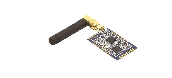
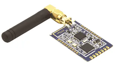
LW-M023-VB is the latest LoRa RF module launched by Lowan Technology. Based on LLCC68 chip development, the module has the advantages of low cost, low power consumption, long distance, strong anti-interference and penetration ability, etc., and can be widely used in the Internet of Things, three-meter set reading and other fields.
In order to shorten the product development cycle, save cost investment, faster and better to meet the market Internet of Things product demand. Lowan technology provides customers with complete hardware and software reference solutions and technical support.
Applications
- Smart Cities
- Security Sensors
- Smart Meters
- Agriculture Sensors
- EA-Eco
- Smart logistics
- Smart Building
- Smart Home
- Manufacture
Module Package Information
Module Dimension
| Length (mm) | Wide (mm) | Thickness (mm) | Pin Size (mm) | Pin Pitch (mm) | Size of shielding case (mm) | PCB thickness (mm) |
| 18.4 | 18.4 | 2.8 | 1.0*0.8 | 2.0 | 17.5*15.4*1.8 | 1.0 |
Note: Range of dimensional within 0.2mm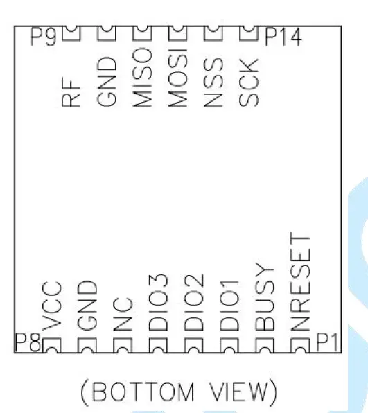
| Number | Name | Direction | Description | Note |
| 1 | NRESET | I | Reset signal, active low | |
| 2 | BUSY | O | SPI busy indicator | |
| 3 | DIO1 | O | Multipurpose digital IO | |
| 4 | DIO2 | O | Multipurpose digital IO-RF switch control | |
| 5 | DIO3 | O | Multipurpose digital IO | |
| 6 | NC | – | No connection | |
| 7 | GND | I | Ground | |
| 8 | VCC | I | Power supply | |
| 9 | RF | I/O | RF IO | |
| 10 | GND | I | Ground | |
| 11 | MISO | O | SPI slave output | |
| 12 | MOSI | I | SPI slave input | |
| 13 | NSS | I | SPI slave select | |
| 14 | SCK | I | SPI clock |
Electrical Characteristics
Absolute Maximum Ratings
| Parameter | Min | Max | Note |
| Power Supply Voltage(V) | -0.5 | 3.9 | |
| Operating Temperature(℃) | -40 | 85 | |
| Input RF level(dBm) | – | 10 |
Operating Parameter
| Parameter | Min | Type | Max | Note |
| Operating Voltage(V) | 1.8 | 3.3 | 3.7 | |
| Operating Temperature(℃) | -40 | – | 85 | |
| Frequency Offset(KHz) | -10 | – | 10 | |
| Frequency bands(MHz) | 860 | 915 | 935 | Can be customized according to customer requirements |
| Transmit Output Power(dBm) | 19 | 20.5 | – | Set Power 22dBm |
| Receive Sensitivity(dBm) | -129@125KHz SF9 -129@250KHz SF10 -127@500KHz SF11 | LoRa® SF=5~9 for BW=125kHz LoRa® SF=5~10 for BW=250kHz LoRa® SF=5~11 for BW=500kHz | ||
| Data Rate(Kb/s) | 1.76 | – | 62.5 | Min. for SF9, BW_L=125kHz Max. for SF5, BW_L=500kHz |
| Modulation Techniques | LoRa\FSK\GFSK | |||
| Package Type | 14 Pin Stamp Pad for PCB SMT mounting | Lead pin pitch 2.0mm | ||
| Communication Interface | SPI | Max 16MHz | ||
| Impedance Matching(Ω) | 50 | |||
Power Consumption
| Mode | Current | Unit | Note |
| TX | 120 | mA | @22dBm |
| RX | 9 | mA | |
| Sleep | 1.5 | uA |
Reference Design
Announcements
- The power supply wiring is as thick as possible. It is suggested that the design can provide 500mA current.
- Radiofrequency interface to the antenna solder part line as short as possible, to 50 Ω impedance matching, walk around the line played more holes.
- The module reset pin suggests that the external environment may cause the module reset by connecting the MCU for control.
- SPI port and DIO port can add pull resistor as needed.
- DIO port should be connected to IO port with external interrupt of MCU as possible.
- Clearance is required around the antenna, it is recommended to set aside a clearance area of 5mm.
- If permitted, the PI circuit is added to the part of the RF outlet to the antenna pad.
- The module of FHSS only uses the private protocol of LoRa. The DTS part uses LoRaWAN;
The module does not support hybrid system mode.
Attached
Integration instructions for host product manufacturers according to KDB 996369 D03 OEM Manual v01.
List of applicable FCC rules
- FCC Part 15.203
- FCC Part 15.207
- FCC Part 15.209
- FCC Part 15.247
Specific operational use conditions
This transmitter/module and its antenna(s) must not be co-located or operating in conjunction with any transmitter. This information also extends to the host manufacturer’s instruction manual.
Limited module procedures
This module is intended for OEM integrators. The OEM integrator is still responsible for the FCC compliance requirement of the end product which integrates this module. 20cm minimum distance has to be able to be maintained between the antenna and the users for the host this module is integrated into. Under such a configuration, the FCC radiation exposure limits set forth for a population/uncontrolled environment can be satisfied. The antenna used should be limited to same type with equal or lesser antenna gain.
According to FCC Part 15 Subpart C Section 15.212, the radio elements of the modular transmitter must have their own antenna. However, due to there is no antenna for this Module, this module is granted as a Limited Modular Approval. When this Module is installed into the end product, a Class II Permissive Change or a New FCC ID submission is required to ensure the full compliance of FCC-relevant requirements.
Trace antenna designs
It is “not applicable” as trace antenna which is not used on the module.
RF exposure considerations
This equipment complies with FCC RF radiation exposure limits set forth for an uncontrolled environment.This compliance to FCC radiation exposure limit for an uncontrolled environment, and a minimum of 20cm separation between antenna and body. The host product manufacturer would provide the above information to end users in their end-product manuals.
Antennas
Spring antenna; 0dBi; 902MHz~928MHz.
Label and compliance information
The end product must carry a physical label or shall use e-labeling followed by KDB784748D01 and KDB 784748 stating “Contains Transmitter Module FCC ID: 2AXQT-LWM023VB”.
Information on test modes and additional testing requirements
The module can be tested with a customized bottom plate. It can enter different testing modes through serial port command configuration. The format of serial port command is as follows:
*SET999999LRTE=A,B,C,D,E
- “*SET999999LRTE=” is the frame header of the command, each command must be added.
- “A” is the selection of module testing mode. 0,1,2,3 can be representing standby mode, sending mode, receiving mode and multi-carrier communication mode.
- “B” is the center frequency point for the module in Hz. The frequency range of this part is 904000000Hz to 925000000Hz.
- “C” is the SF value set for the module(SF: Spread spectrum Factor), which can be set within the integer value of 5-12.
- “D” is the transmitting power of the module, the unit is dBm, and the transmitting power should not exceed 22dBm.
- “E” is the bandwidth of the module. The command can be entered in 0#, 1#, and 2#, respectively representing the bandwidth of 125kHz,250kHz, and 500kHz.
Example: *SET999999LRTE=1,904000000,7,20,2# : the module takes 904MHz as the central frequency point and SF value is 7 to send RF signals with bandwidth of 500kHz and transmitting power of 20dBm.
Limited modules are built into the host device. The host device requires additional application procedures (for example: C2PC) certification and re-evaluation of the radiation spurious emission test to meet FCC compliance
Additional testing, Part 15 Subpart B disclaimer
The modular transmitter is only FCC authorized for the specific rule parts (FCC Part 15.247) listed on the grant, and that the host product manufacturer is responsible for compliance to any other FCC rules that apply to the host not covered by the modular transmitter grant of certification. The final host product still requires Part 15 Subpart B compliance testing with the modular transmitter installed when contains digital circuity.


