![]() CHASSIS MRC 1st Gen S-10 8.50 Cage
CHASSIS MRC 1st Gen S-10 8.50 Cage
User Manual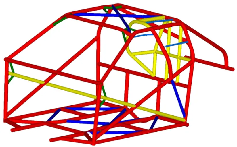
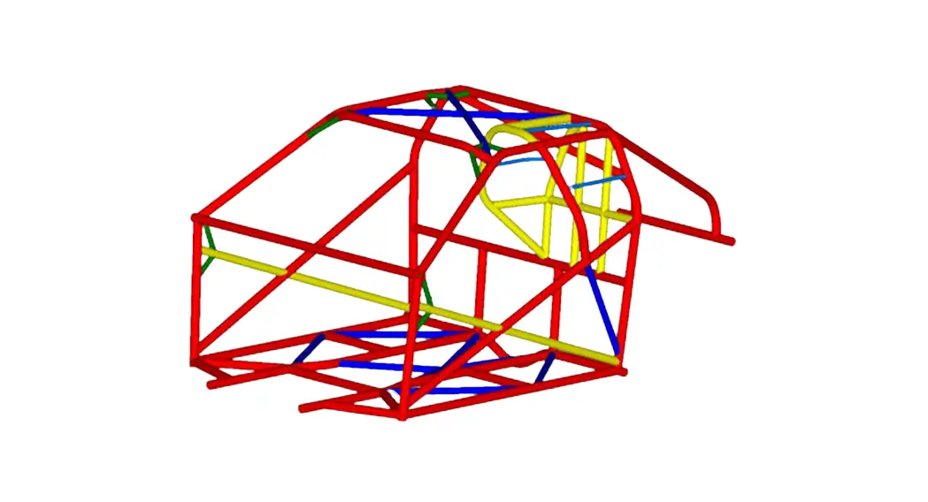
MRC 1st Gen S-10 8.50 cage
Thank you for choosing MRC for your cage kit!
We hope we made this as painless as possible.
If there are any questions this sheet doesn’t cover, Please contact us by phone, Email or
MRC 1st Gen S-10 8.50 Cage
This guide is to be a supplement to common roll cage installation techniques. Some portions are not covered in this guide. We have supplied you with some pictures to guide you. More pictures are available on our face book and website.
Commonly used tools
- Tag or MiG welder (If chromoly, The process has to be Tag welded)
- Grinder to fit tubes, finish tube notches, clean floors
- We recommend a tube notched to make notches, But a grinder will work also.
- Digital protractor
- Tape measure
- Sand paper or sander to clean tubing of mill scale to weld
- Wire wheel and flap disk to remove paint and seam sealer
- Ratchet strap
Before we begin, Make sure the car is level, front to back and side to side.
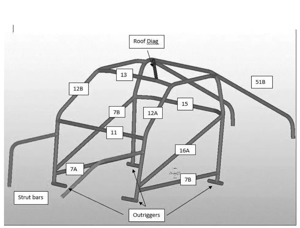
| Part Name | Material | Length | Bends |
| 51B | 1.625 .083 | 57 1/16 | 1 |
| 15 | 1.625 .083 | 53 ¾ | 2 |
| MAIN HOOP | 1.625 .083 | 129 ¾ | 4 |
| 12A | 1.625 .083 | 76 11/16 | 3 |
| 12B | 1.625 .083 | 76 11/16 | 3 |
| 13 | 1.625 .083 | 44 | 2 |
| 51B | 1.625 .083 | 57 1/16 | 1 |
| STRUT BAR | 1.500 .065 | 43 5/8 | 1 |
| STRUT BAR | 1.500 .065 | 43 5/8 | 1 |
| OUTRIGGER | 1.625 .083 | 8 | 0 |
| OUTRIGGER | 1.625 .083 | 8 | 0 |
| OUTRIGGER | 1.625 .083 | 8 ¼ | 0 |
| OUTRIGGER | 1.625 .083 | 8 ¼ | 0 |
| ROOF DIAG | 1.250 .058 | 39 3/16 | 0 |
| 16A | 1.625 .083 | 50 3/16 | 0 |
| 16B | 1.625 .083 | 50 3/16 | 0 |
| 7B | 1.625 .083 | 42 7/16 | 0 |
| 7A | 1.625 .083 | 42 7/16 | 0 |
| 11 | 1.625 .083 | 52 3/16 | 0 |
Step One
Holes need to be cut in the floor to be able to run the cage through. Cut enough to drop the cage, but not to much where it’s a pain to place tin over the hole. Make sure you clean the edges of the hole as to not cut yourself and to make laying tin down easier later on.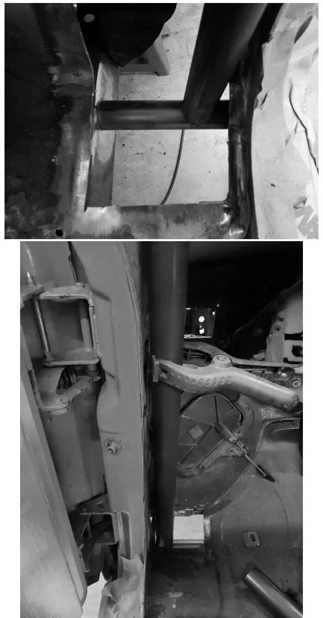
Step 2.
Start by cleaning the frame for welding. There are some holes in the factory frame that may need filled to put the tubes over. We patch and grind flat. The measurement below is from outrigger to outrigger, it does not set the cage in the truck. Use our pictures as a reference to where to set it. Once the outriggers are set, use the supplied caps to finish the ends of the tubes. Tack in place 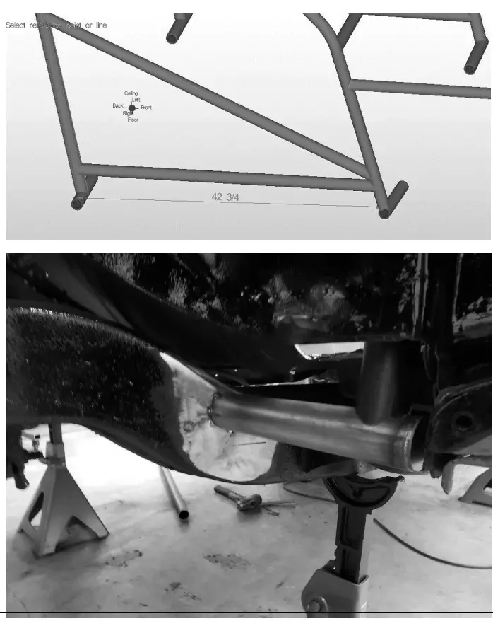
Step 3.
Once the outriggers are tacked, The main hoop gets set. The lay back of the main hoop is set at 7 degrees from vertical. Begin notching the bottom of the main hoop to the outrigger. Take this step slowly. As this sets your height for the rest of the cage. Tack in place. 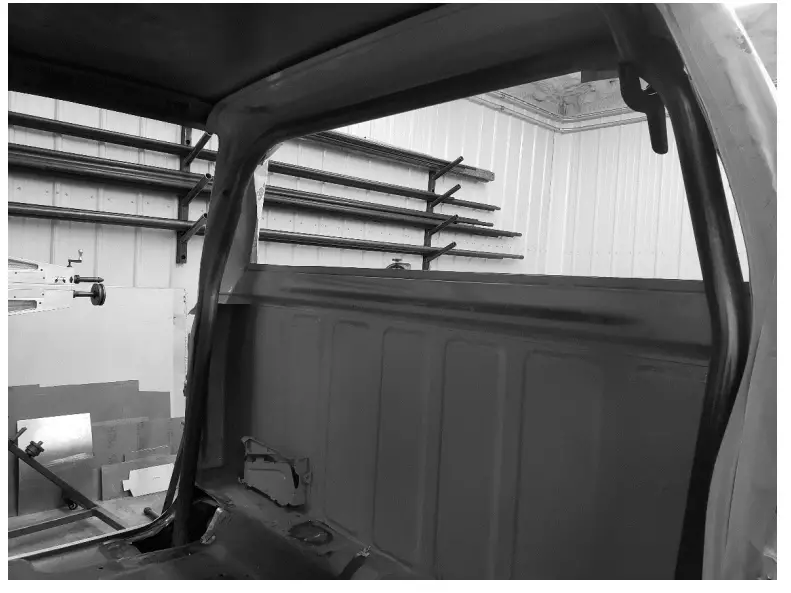
Step 4.
After the main hoop is set and tacked, the a-pillars will be set in place. We sometimes use a ratchet strap to hold the main hoop in place, when fitting the a-pillars, it may push the main hoop back. So watch that. The a-pillars will fit very tightly to the body of the truck. Once again, begin notching both ends. Working them slowly together to fit the bar. The top portion of the a-pillars should be level with the truck. 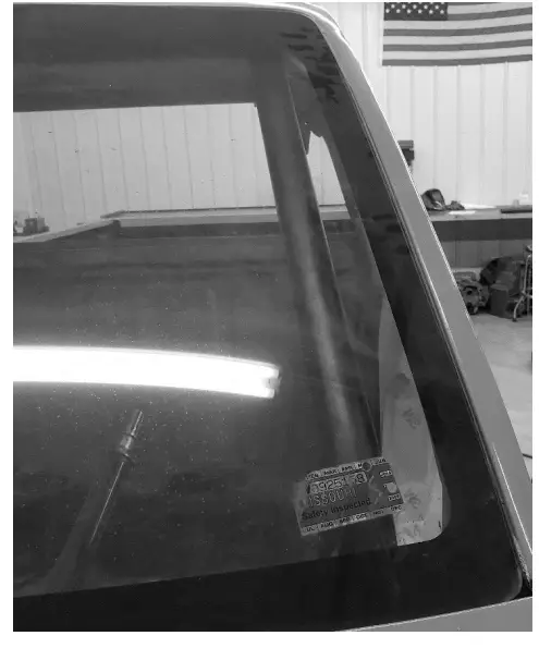
Step 5.
When the a-pillars are both set and tacked, The windshield bar can be fit. This bar can be set as high and tight as you want. We left plenty of material for you to fit it where you want and like.
Step 6.
Dash Bar will be fit after the windshield bar, Once again, this can be set where you prefer
Step 7.
Harness bar can be fit after the dash bar, be careful when fitting this bar, it is deceiving on how much you need to take out. Make sure you are fitting if from the back and not just the front, Bring the notches to the main hoop from the back. Its easy to take too much and scrap the bar.
Step 8.
Note : (Leave the door bars and rocker bars out for now. They will get fit after the cage is raised back up.)
At this point, you can go ahead and weld all the joints you see except for the outrigger to frame connection. This way the cage can be dropped down to weld the top portions of the cage. Once everything is welded and will stay in place, break the tacks free from the frame to the outriggers. And the cage will drop and you can weld all the way around the top of the cage. (Now would also be a good time to fit the roof bar if that option was selected.)
Step 9.
Raise the cage and level it out again, you should be able to see where the old tacks are to give you a reference of about where the cage sat. But use your protractor all over to level it out again. You can now weld the cage to the frame.
Step 10.
After the cage is leveled out and welded in, now is the time to set the door bars and rocker bars. Door bars need to meet the drivers arm between the shoulder and elbow. So set accordingly. Now would be a good time to test fit your seat and get things comfortable.
Step 11.
Once the main cage is complete, the rear down bars need to be fit. This cage, if fit correctly, sets the main hoop right at the bottom of the rear window. You may need to grind a small spot where the cage comes through the rear window seal area. This allows the cage to be fit as tight as possible. We set the rear down bars on the frame right over the rear axle.
Step 12 Optional engine bay bars
If purchased, now Is the time to cut a hole in the firewall to fit the forward engine bay bars.
Easiest way is with a hole-saw. On the frame, there is a seam that needs to be leveled out. We have supplied a 6×6 .125 plate to level out the frame to provide a nice place to land the bar.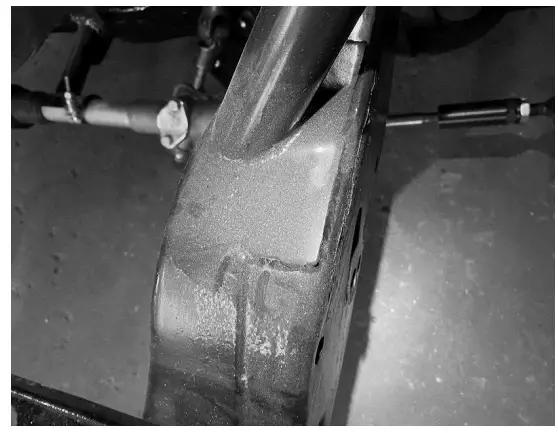
Warranty: There is no warranty stated or implied due to unusual stresses placed on race cars and components because we have no control over how they are maintained and used.
Moore Race Chassis and fabrication LLC accepts no liability for failures of racing products manufactured or sold by MRC. The customer accepts all risks involved with racing and hazards thereof, MRC makes no claims nor does it intend for it’s products to be used on street driven vehicles.
![]() Facebook Messenger.
Facebook Messenger.
Phone – (636) 791 1541
Email – [email protected]


