![]() M219
M219
80286 Mainboard
User’s Guide
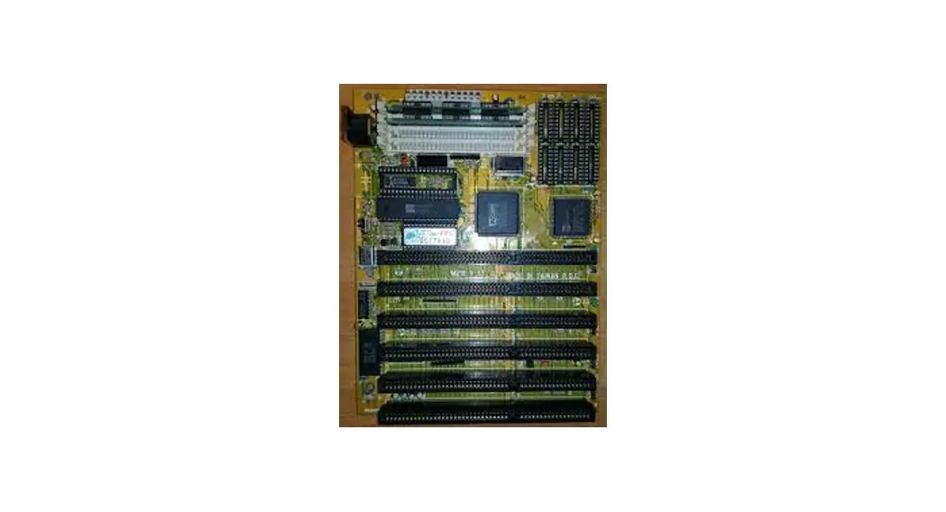
M219 Motherboard
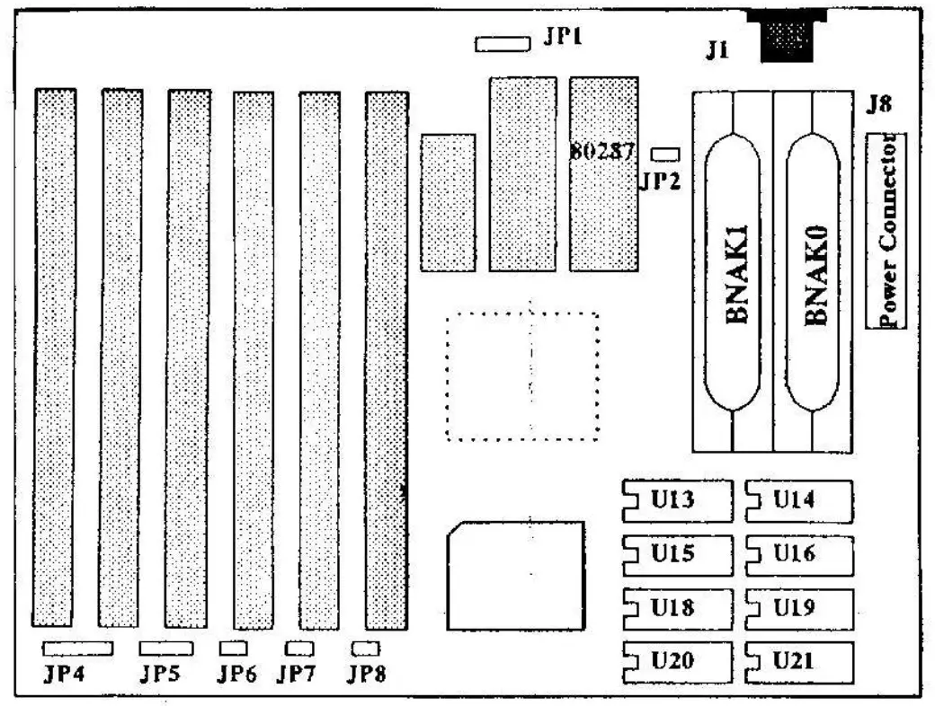
Jumper, Connector, and Socket Locations
KEY FEATURES
- Single chip for 80286 16/20/25 MHZ system
- Socket support for 80287 coprocessor
- Page mode and block interleave DRAM management
- Memory configurations from 512KB to 16MB using combinations of 256KB,512K,1M and 4M SIMM modules
- Support hardware and software turbo switch
- Support shadow RAM for system and video BIOS
- Six 16-bit I/O slots
- External and rechargeable battery-backed CMOS RAM for real time clock and system configuration
- PCB with dimensions of 220mm x 170rnm
JUMPER SETTING AND CONNECTORS
JP1External battery connector
Pin 1: VDD(6V) Pin 4: Gnd
Pin 2,3: Rechargeable battery pin
JP2. Display type select
Close: Color
Open: Monochrome
JP4. Power LED and keylock connector
Pin 1: LED power
Pin 2: Not used
Pin 3: Gnd Pin
4: Keyboard inhibiter
Pin 5: Gnd
JP5. Speaker connector
Pin 1: Data out
Pin 2: Not used
Pin 3: Gnd
Pin 4: +5Vdc
JP6. Turbo LED connector
Pin 1: + Anode Pin 2: -cathode
JP7. Turbo switch connector
Close: Turbo speed
Open: Low Speed
You can also switch the clock speed using software control via keyboard commonds.
CTRL,ALT,[ +.]: Press these three keys simultaneously to select Turbo Mode,
CTRL,ALT,[ — ]:Press these three keys simultaneously to select LOW Speed Mode.
7P8. Reset connector
Close: Reset Open: Not reset
| MODE | DRAM TYPE | TOTAL MEMORY | |
| BANKO | BANK! | ||
| 1 2 3 4 5 6 7 8 | 256K 256K 512K 512K 1M 1M 4M 4M | x 256K x 512K x 1M x 4M | 512KB 1MB 1MB 2MB 2MB 4MB 8MB 16MB |
![]()


