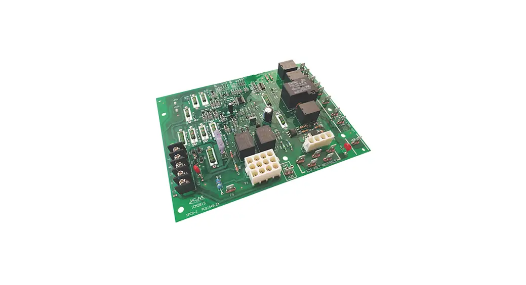
![]() ICM2913
ICM2913
Gas Ignition Replacement Board
![]()

Installation, Operation & Application Guide
For more information on our complete range of American-made products – plus wiring diagrams, troubleshooting tips and more, visit us at www.icmcontrols.com
FEATURES
- Controls blower motors, gas valve, & spark ignitor in sequence
- Protects against short cycling
- Selectable Heat/Cool blower off-delay time
- Flash codes from the onboard LED indicate specific problems for easier troubleshooting
- Repeated ignition failures or flame losses will disable heat operation for safety
INTRODUCTION
The ICM2913 is a form, fit, and functional replacement for the boards shown in the cross-reference section of this guide. The control boards are designed as automated gas ignition controls which monitor the ignition sequence including the inducer, pressure switch, spark ignition, gas valve, flame sense, and circulating blower while maintaining full safety circuit monitoring including the high limit switch, roll out switch and auxiliary limit switch circuits. Onboard diagnostics will indicate when a fault condition exists.
SPECIFICATIONS
- Line voltage: 240 VAC
- Line frequency: 50/60 Hz
- Control voltage: 18-30 VAC
- Circulator blower: 10 FLA, 30 LRA @ 240 VAC
- Inducer blower: 0.7 FLA, 1.5 LRA @ 240 VAC
- Combined gas valve load: 1.5 A @ 24 VAC
- Minimum flame signal threshold: 0.75 uA
OPERATION
On a call for heat (24 VAC on the W input), the following occurs:
- Upon a call for heat the control checks the status of the pressure switch; if the pressure switch is open, the control will energize the draft inducer.
- When the control verifies the pressure switch has closed, the control will start a 20-second prepurge.
- When the pre-purge time delay is over, the control will energize the gas valve and initiate spark.
- The ignitor must be de-energized when the flame is sensed or at the conclusion of the trial for ignition period, whichever comes first.
- When flame is sensed, the control will energize the circulator fan within the ON-delay period.
When the call for heat is terminated, the following occurs:
- The control shall de-energize the gas valve and the draft inducer within the post purge period.
- When the heat mode fan OFF delay timer expires, the control will de-energize the circulator fan.
With a call for cooling, the following occurs:
On a call for cooling (24Vac on Y and G), the circulator fan is energized within the cool on delay period.
The control will ignore a call for Y without a call for G. After the thermostat is satisfied, the compressor is de-energized and the jumper selected cool Off delay period begins. Following the cooling Off delay period, the circulator fan is de-energized.
> > > CAUTION < < <![]() ELECTRICAL SHOCK HAZARD! Before installing this unit, turn off power at the main service panel by removing the fuse or switching the appropriate circuit breaker to the OFF position. Follow all Local, State and National Electrical Codes when installing this device.
ELECTRICAL SHOCK HAZARD! Before installing this unit, turn off power at the main service panel by removing the fuse or switching the appropriate circuit breaker to the OFF position. Follow all Local, State and National Electrical Codes when installing this device.
CAUTION! Only trained personnel should install or service heating equipment. When working with heating equipment, be sure to read and understand all precautions in the documentation, on labels, and on tags that accompany the equipment. Failure to follow all safety guidelines may result in damage to equipment, severe personal injury or death.
REMOVE EXISTING CONTROL
CAUTION! To service control, and prior to disconnection, label all wires. Failure to do so may result in wiring errors that can cause dangerous operation.
- Turn thermostat to the OFF position or set it to the lowest possible setting.
- Turn OFF the electrical supply to furnace.
- Turn OFF the gas supply to furnace.
CAUTION! Failure to turn off gas and electric supplies can result in explosion, fire, death or personal injury. - Remove the furnace blower and control access doors.
- Disconnect the thermostat wires and humidifier wires (if equipped with a humidifier).
- Disconnect the line voltage, blower, electronic air cleaner wires (if equipped) and transformer wires.
- Remove screws and any other fasteners and the old circuit board.
- Examine the control and the control box for water stains.
- Make repairs if any sources of water leakage are found. Be sure to check humidifiers, evaporator coils and vent systems in the area of the control.
INSTALL NEW CONTROL
- Ground yourself. When handling the circuit board; hold it by the edges.
- Fasten the circuit board with the retaining screws.
- Connect all line voltage, low voltage and accessory wires.
- Verify the sequence of operation.
REPLACES
TRANE P/N #: D674711P01
FAULT CODES, STATUS LIGHTS AND TROUBLESHOOTING
| Flashes | Fault Condition | Trouble Shooting |
| Sad RED | Internal Control Board error | Internal board failure, replace control board |
| Sad RED w/Solld Status LED | Continuous reset | Reset caused by internal board failure, replace the control board |
| 2 | Lockout | The number of retry’s or recycles has exceeded the limit for the control. Clean or replace the flame sensor, check the igniter for proper operation & input voltage, check the transformer% common is grounded to earthground. |
| 3 | Pressure switch or Inducer error | Check for obstructed pressure switch tubing or defective pressure switch. Check for oxidation on terminals, broken wires, or defective inducer motor . Check for proper voltage at the inducer motor input. |
| 4 | Open limit switch | Check for blocked airflow, blocked ductwork, and dirty filter. Check or replace high limit switch if defective. |
| 5 | False Flame | Flame was sensed when no flame is present. Check or replace flame sensor and check the grounds. |
| 6 | Not used | |
| 7 | External Gas valve circuit error | Check the wires going to the gas valve for proper connection and ensure the gas valve is not mis-wired. Also, check for corrosion on gas valve terminals and clean up the gas valve ground. |
| 8 | Low flame sense | A multimeter can be used to test flame sense by placing the meters probes on the two test pins and taking a DC voltage reading while the flame sensor is in the presence of flame. 1VDC = 1pA flame current. Weak or poor flame sense is represented by a reading of 0.7 VDC or lower. |
Fault code retrieval & clearing
When powering on, the control flashes the last four error codes that have occurred in the last 14 days. The control will flash the newest error first and oldest error last. The fault memory can be manually erased by powering on with a G call in place and toggling W three times.
Two LED’s on the board
- Status LED (Green)
— Slow Flash: Normal operation with a cool or fan call only.
— Fast Flash: Normal operation with call for heat only. - Fault LED (Red)
— See table
LOCK OUT CONDITION
The control will go into a 1-hour soft lockout if the following faults are detected:
- Limit switch open 4 times in one heat call
- Ignition failed (flame not sensed) 4 times in one heat call
- Flame lost after successful ignition 3 times in one heat call
- Gas valve sensed on when it should not be
- Gas valve sensed off when it should be on, 10 times in one heat call
**NOTE: Flame sensed while the gas valve is closed puts the control in lockout state, but lockout clears after the blower off delay is complete (90 seconds or 60 seconds, depending on jumper selection).
FLAME LOSS DIAGNOSTICS
| Weak or intermittent spark | Make sure the furnace frame is grounded to earth ground. Ensure the common of the 24 VAC is grounded to Earth ground. Check or replace the spark igniter. Check the primary and secondary voltage of the transformer for proper voltage. |
| Flame Loss | • Check for bad or dirty flame sensor • Check thermostat • Check for proper flame sense signal at flame sense test pins • Check for proper earth ground on furnace. • 4 flame losses in a single heat call will put the control into a one-hour lockout. |
| No flame/Ignition failure | • Check the thermostat • Check the pressure switch • Check gas valve operation • Check for good spark & check for good earth ground |
| Flame out of sequence | Flame out of sequence represents a scenario where flame is sensed while the gas valve is closed. The control goes into a lockout state when flame is out of sequence and the indicator LED blinks the appropriate code (see lockout” section). • Check and replace flame sensor |
| Furnace does not ignite and main blower runs continuously | Check the high temperature limit switch for open circuit. Check all safeties. Clean or replace air filter. Check duct work and return air ducts for blockages. |
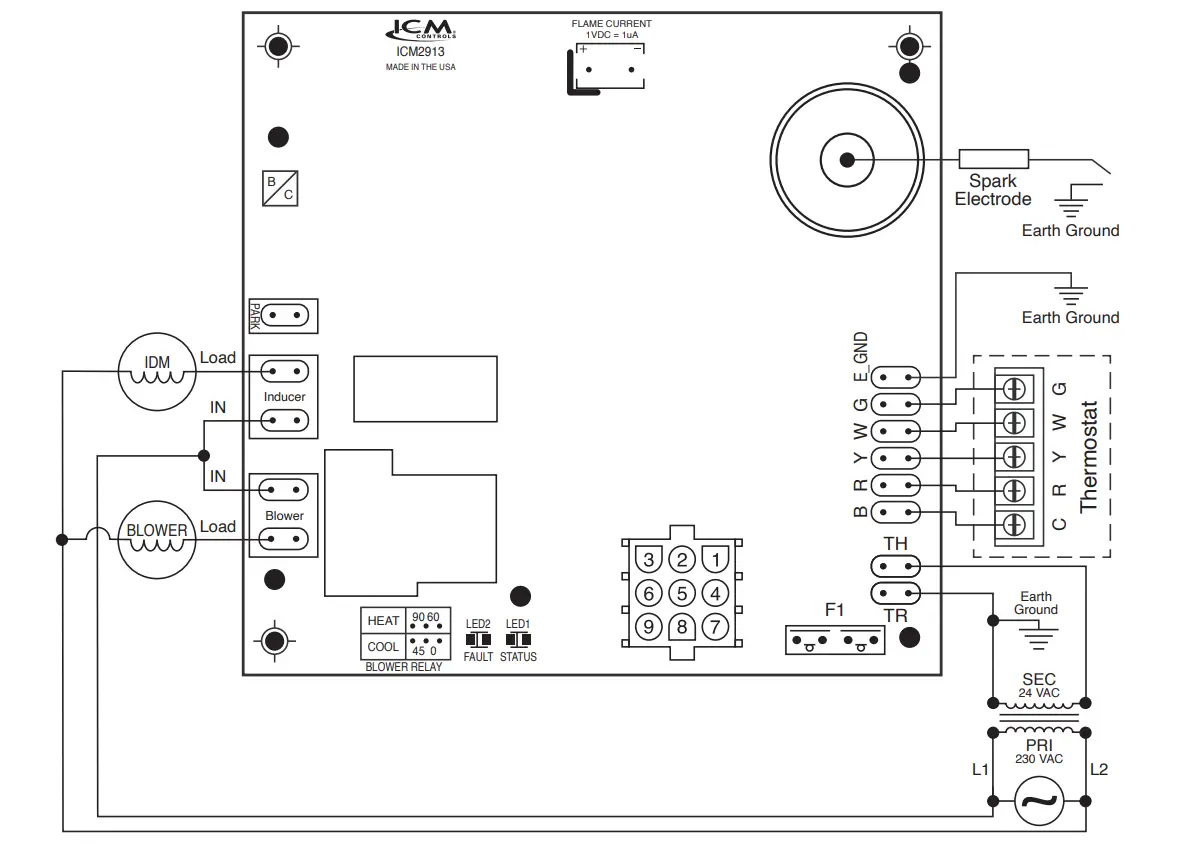
WIRING DIAGRAM
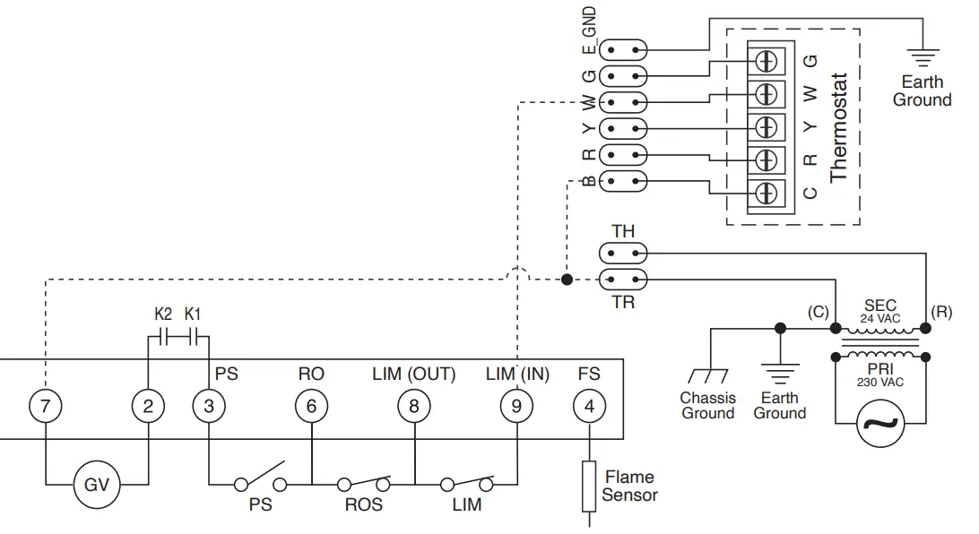
CONNECTION DIAGRAM
LEGEND
| B | 24 VAC common |
| C | 24 VAC common |
| ECM | N/A |
| F1 | Fuse |
| FS | Flame sensor |
| GND | Ground |
| GV | Gas valve |
| IDM | Induced draft motor |
| K1, K2 | Gas valve relays |
| LIM | Limit switch |
| PRI | Transformer primary |
| PS | Pressure switch |
| R | 24 VAC |
| ROS | Roll out switch |
| SEC | Transformer secondary |
| TH | Transformer 24 VAC hot |
| TR | Transformer 24 VAC common |
9-PIN CONNECTION
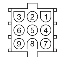
- N/A
- Gas valve
- Pressure switch in
- Flame sensor
- N/A
- Fusible link (Roll out switch)
- Common (24 VAC), B
- Limit switch (out)
- Limit switch (in)


 Replacement Kit Instruction Manual")


