
ICM CONTROL ICM2812 Hot Surface Ignition Control Board
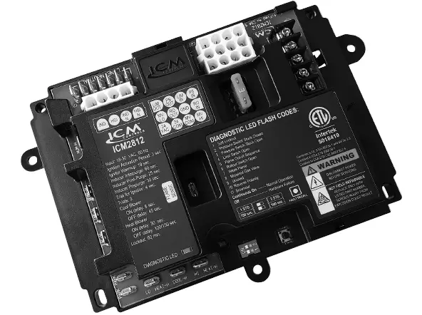
The ICM2812 is a furnace control board that replaces 150 other furnace control boards. It comes with LED diagnostics to assist in troubleshooting, and fault code information can be found in the application guide provided. Safety considerations must be followed at all times when installing or servicing heating equipment, and only trained personnel should do so. Electrostatic discharge (ESD) precautions must also be taken to avoid damage to electronic components. The old circuit board must be removed before installing the new control board.
Specifications:
- Outputs:
Installation Instructions:
- Disconnect all power to the furnace before beginning installation.
- Ground yourself by touching your hand and tools to a clean, metal (unpainted) furnace surface near the control board.
- To remove existing control, turn thermostat to OFF position or set it to the lowest possible setting. Turn OFF electrical supply to furnace and turn OFF gas supply to furnace. Remove furnace blower and control access doors. Disconnect thermostat wires and humidifier wires (if equipped with a humidifier). Disconnect line voltage, blower, electronic air cleaner wires (if equipped), and transformer wires. Remove screws and any other fasteners, and the old circuit board. Examine control and control box to check for water stains. Make repairs if any sources of water leakage are found.
- To install new control, ground yourself again. When handling circuit board, hold it by the edges. Fasten circuit board with retaining screws. Connect all line voltage, low voltage, and accessory wires.
- Verify the sequence of operation before turning on power and gas supply to the furnace.
For more information on our complete range of American-made products – plus wiring diagrams, troubleshooting tips and more, visit us at www.icmcontrols.com
FEATURES
- Hot Surface Ignition (HSI) control board
- Microprocessor-based
- Monitors timing, trial for ignition, system switches, flame sensing and lockout.
- 100% lockout safety feature
- Compatible with LP or Natural Gas
- LED indication for status and fault codes to aid in troubleshooting
- ICM2812 includes a replacement board only
- ICM2812-KIT includes cable harnesses for compatibility with more than 150 furnace control boards.
INTRODUCTION
The ICM2812 has incorporated LED diagnostics to assist in troubleshooting. Fault code information can be found in this application guide. Please keep this application guide with the furnace installation manual for future reference.
SAFETY CONSIDERATIONS
Only trained personnel should install or service heating equipment. When working with heating equipment, be sure to read and understand all precautions in the documentation, on labels, and on tags that accompany the equipment. Failure to follow all safety guidelines may result in damage to equipment, severe personal injury or death
SPECIFICATIONS
- Control voltage: 24 VAC (18-30 VAC), 60 Hz
- Line voltage: 120 VAC, 60 Hz
- Operating temperature: -40˚to 175˚F (-40˚to 80˚C)
OUTPUTS
- HSI Hot Surface Ignitor: 6 amp @ 120 VAC
- Gas Valve: 1.5 amp @ 24 VAC
- Inducer draft motor: 2.2 FLA @ 120 VAC
- Blower motor: 9.5 FLA @ 120 VAC
ELECTROSTATIC DISCHARGE (ESD) PRECAUTIONS
CAUTION!
Use caution when installing and servicing the furnace to avoid and control electrostatic discharge; ESD can impact electronic components. These precautions must be followed to prevent electrostatic discharge from hand tools and personnel. Following the precautions will protect the control from ESD by discharging static electricity buildup to ground.
- Disconnect all power to the furnace. Do not touch the control or the wiring prior to discharging your body’s electrostatic charge to ground.
- To ground yourself, touch your hand and tools to a clean, metal (unpainted) furnace surface near the control board.
- Service the furnace after touching the chassis. Your body will recharge with static electricity as you shuffle your feet or move around, and you must reground yourself.
- Reground yourself if you touch ungrounded items.
- Before handling a new control, reground yourself, this will protect the control. Store the used and new controls in separate; containers before touching ungrounded objects.
- ESD damage can also be prevented by using an ESD service kit.
REMOVE EXISTING CONTROL
CAUTION: To service control, and prior to disconnection, label all wires.
Failure to do so may result in wiring errors that can cause dangerous operation.
- Turn thermostat to OFF position or set it to the lowest possible setting.
- Turn OFF electrical supply to furnace.
- Turn OFF gas supply to furnace.
CAUTION: Failure to turn off gas and electric supplies can result in explosion, fire, death, or personal injury. - Remove furnace blower and control access doors.
- Disconnect thermostat wires and humidifier wires (if equipped with a humidifier).
- Disconnect line voltage, blower, electronic air cleaner wires (if equipped), and transformer wires.
- Remove screws and any other fasteners, and the old circuit board.
- Examine control and control box to check for water stains.
- Make repairs if any sources of water leakage are found. Be sure to check humidifiers, evaporator coils, and vent systems in the area of the control.
INSTALL NEW CONTROL
- Ground yourself. When handling circuit board, hold it by the edges.
- Fasten circuit board with retaining screws.
- Connect all line voltage, low voltage, and accessory wires.
- Verify the sequence of operation.
SEQUENCE OF OPERATION
On the application of power, the ICM2812 will continuously monitor the rollout switch, limit switch, pressure switch, gas valve output and flame sense.
During a Call for Heat, the control makes sure the limit switch is closed and the pressure switch contact is open before turning on the Inducer blower, which will be energized for the 30-second pre-purge. Following the pre-purge period, the pressure switch contact is closed and power is applied to the hot surface ignitor (there is a 19-second warm-up period), both gas valves are energized. Once flame is established and sensed the ignitor is turned off. 1STG (Single Stage): After the 30 seconds heat blower on delay the high (HI HEAT-H) speed is energized. 2STG (Dual Stage):
- After 5 seconds the high gas valve (MV HI) is turned off. The low (LO HEAT-H) speed blower will energize after the 30 seconds heat blower on delay. The ICM2812 will switch to second stage heat after 5 minutes of continuous operation; the high gas valve (MV HI) is re-energized along with the low gas valve (MV LO) and the main blower will switch to the high (HI HEAT-H) speed for the duration of the heat call.
- Once the heat call is satisfied; the blower is switched to the low (LO HEAT-H) speed; the Inducer Draft motor turns off after the 25 second post purge delay and the blower motor turns off after the preselected heat blower off delay of either 100 or 150 seconds.
- Fan: A fan call from the thermostat will energize the blower motor without delay at low (LO HEAT-H) speed. The blower is turned off without delay when the Fan call is removed.
- Cooling: A cooling call from the thermostat will energize the blower motor at high (COOL-H) speed after the 6 second cool blower on delay. The blower is turned off 45 seconds after the cooling call is satisfied
FLAME SENSE TROUBLESHOOTING TIPS
Flame not established
- If flame is not established during the 4 second initial sequence then the control will start the next trial for ignition in 60 seconds.
- There will be 2 more attempts to ignite after the 60 seconds delay, before the respective fault code is triggered and the ignition trials are stopped.
- If flame has not been established after the 3 trials for ignition; the control will enter a 60 minute soft lockout and flash the respective fault code. The lockout can be cleared by cycling the W call or the input power.
- The blower motor is off until 30 seconds after flame is established and sensed.
Flame out
- Flame out
Flame out is considered when flame is lost during heating. - When a W signal is present and flame is not sensed, then gas valve will disengage until the next trial for ignition.
If flame is not established on the immediate sequence (2 above) then the control will continue with 2 additional trials for ignition. - The Inducer and Blower motors will continue running during the flame out scenario.
Flame out of sequence
- Flame out of sequence represents a scenario when flame is sensed while the gas valve is de-energized.
- The Inducer and Blower motors will be engaged (if not already running) and continue running for as long as the fault condition is present
ICM2812 TIMING
| Input | 18-30 VAC, 60Hz |
| Ignition Activation Period | 3 seconds |
| Ignitor Warm-up | 19 seconds |
| Inducer Inter-purge | 60 seconds |
| Inducer Post-Purge | 25 seconds |
| Inducer Pre-purge | 30 seconds |
| Trial for Ignition | 4 seconds |
| Trials | 3 |
| Cool Blower OFF delay | 45 seconds |
| Cool Blower ON delay | 6 seconds |
| Heat Blower OFF delay | 100/150 seconds |
| Heat Blower ON delay | 30 seconds |
| Lockout | 60 minutes |
- To review the fault history; press and hold the Fault Recall button and release once the LED goes out. The previous five fault codes will be displayed. The LED will turn off momentarily and then go solid after the last fault has been displayed.
- The ICM2812 will not respond to thermostat calls while the fault history is being displayed.
- To clear the fault history; press and hold the Fault Recall button and release once the LED starts flashing. The LED will turn off momentarily and then go solid after the fault history has been cleared.
- The fault history will not erase while the ICM2812 is performing a heating or cooling call.
LED FAULT CODES
| LED Status | Description | Trouble Shooting Tips |
| ON | Normal operation | N/A |
| OFF | Control board failure | Check for proper input voltage and check the fuse; if not resolved replace the control. |
| 1 | Ignition failure (soft lockout) | Clean or replace the flame sensor, check the igniter for proper operation & input voltage, check the transformer’s common is grounded to earth ground. |
| 2 | Pressure switch stuck closed | Check for contaminated or defective pressure switch. |
| 3 | Pressure switch stuck open | Check for obstructed pressure switch tubing or defective pressure switch. Check for oxidation on terminals, broken wires, or defective inducer motor . |
| 4 | Limit switch fault | Checked for blocked airflow, blocked duct work, and dirty filter. Check or replace high limit switch if defective. |
| 5 | Flame out of sequence | Check for intermittent or defective gas valve and check for dirty or defective flame sensor. |
| 6 | Roll out switch fault | Check for a cracked heat exchanger, defective rollout switch , broken wires on the roll out switch, or replace roll out switch if required. |
| 7 | Weak flame | Weak flame is caused by carbon build up on the flame sensor, poor grounds, or improper placement of the flame sensor . Clean or replace the flame sensor, reassure grounds, ensure the flame sensor is fully enveloped in the flame. |
| 8 | Mis–wired gas valve | Check for shorted or mis–wired gas valve, check harness wires for any shorts or breaks, and check the pressure switch for proper operation. |
| 9 | Unused | N/A |
| 10 | Hot and neutral reversed | Check for proper polarity of the incoming voltage on the primary and secondary sides of the transformer. |
| 11 | Brownout | A brownout fault indicates a low voltage condition. Check the voltage on the primary and secondary sides of the transformer and ensure there is no excessive load on the transformer. |
ICM2812-KIT CROSS REFERENCE WIRING
| Manufacturer | Part Number | Harness | |
| Amana/Goodman | 10207701 | 6 | |
| Amana/Goodman | 10207704 | 5 & 6 | |
| Amana/Goodman | 10207706 | 5 & 6 | |
| Amana/Goodman | 10207710 | 5 & 6 | |
| Amana/Goodman | 10207714 | 5 & 6 | |
| Amana/Goodman | 10207717 | 6 | |
| Amana/Goodman | 10207718 | 5 & 6 | |
| Amana/Goodman | 10207719 | 5 & 6 | |
| Amana/Goodman | 10207720 | 6 | |
| Amana/Goodman | 0130F00005(S) | 5 & 6 | |
| Amana/Goodman | 0130F00006(S) | 5 | |
| Amana/Goodman | 102077-02 | 5 & 6 | |
| Amana/Goodman | 102077-03 | 5 & 6 | |
| Amana/Goodman | 102077-04 | 5 & 6 | |
| Amana/Goodman | 102077-09 | 5 & 6 | |
| Amana/Goodman | 10207720S | 6 | |
| Amana/Goodman | B1809926(S) | 5 & 6 | |
| Amana/Goodman | PCB00109 | 5 | |
| Amana/Goodman | PCBBF109 | 5 | |
| Amana/Goodman | PCBBF110(S) | 5 & 6 | |
| Amana/Goodman | PCBBF112(S) | 5 & 6 | |
| Amana/Goodman | PCBBF122(S) | 5 | |
| Amana/Goodman | PCBBF123(S) | 5 & 6 | |
| Amana/Goodman | PCBBF132(S) | 5 | |
| Amana/Goodman | PCBBF134 | 5 & 6 | |
| Amana/Goodman | PCBBF135 | 5 & 6 | |
| Amana/Goodman | PCBBF136 | 5 & 6 | |
| Amana/Goodman | PCBBF138 | 5 & 6 | |
| American Standard/Trane | CNT02789 | 6 | See Note 1 |
| American Standard/Trane | CNT02891 | 6 | |
| American Standard/Trane | CNT03076 | 6 | |
| American Standard/Trane | CNT03798 | 6 | |
| American Standard/Trane | CNT03799 | 6 | |
| American Standard/Trane | CNT05164 | 6 | |
| American Standard/Trane | CNT05165 | 6 | |
| American Standard/Trane | D341122P01 | 6 | |
| American Standard/Trane | D341235P01 | 6 | |
| American Standard/Trane | D341235P03 | 6 | |
| American Standard/Trane | D341396P04 | 6 | |
| American Standard/Trane | D341396P05 | 6 | |
| American Standard/Trane | D34139P03 | 6 | |
| Carrier | HK42FZ004 | 11 & 12 | |
| Carrier | HK42FZ007 | 11 & 12 | |
| Carrier | HK42FZ008 | 11 & 12 | |
| Carrier | HK42FZ009 | 11 & 12 | |
| Carrier | HK42FZ011 | 11 & 12 | |
| Carrier | HK42FZ016 | 11 & 12 | |
| Coleman/Evcon/Lennox/Luxaire/York | G951ADB-1401(C) | 6 | See Note 1 |
| Coleman/Evcon/Lennox/Luxaire/York | G951ADB1402 | 6 | |
| Coleman/Evcon/Lennox/Luxaire/York | G951ADB-1403 | 6 | |
| Coleman/Evcon/Lennox/Luxaire/York | G951AEB-1403 | 6 | |
| Coleman/Evcon/Luxaire/York | 265901 | 6 | |
| Coleman/Evcon/Luxaire/York | 265902 | 6 | |
| Coleman/Evcon/Luxaire/York | 539617 | 6 | |
| Coleman/Evcon/Luxaire/York | 52537074000 | 6 | |
| Coleman/Evcon/Luxaire/York | 52537077000 | 6 | |
| Coleman/Evcon/Luxaire/York | 031-00662 | 6 | |
| Coleman/Evcon/Luxaire/York | 031-00662-700 | 6 | |
| Coleman/Evcon/Luxaire/York | 031-01250-700 | 6 | |
| Coleman/Evcon/Luxaire/York | 031-01266-700 | 6 | |
| Coleman/Evcon/Luxaire/York | 031-01284-000 | 6 | |
| Coleman/Evcon/Luxaire/York | 031-01973-000 | 6 | |
| Coleman/Evcon/Luxaire/York | 031-09166-000 | 6 | |
| Coleman/Evcon/Luxaire/York | 331-01933-000 | 6 | |
| Coleman/Evcon/Luxaire/York | 331-01972-000 | 6 | |
| Coleman/Evcon/Luxaire/York | 331-09167-000 | 6 | |
| Coleman/Evcon/Luxaire/York | S1-03100662000 | 6 | |
| Coleman/Evcon/Luxaire/York | S1-03101250000 | 6 | |
| Manufacturer | Part Number | Harness | |
| Coleman/Evcon/Luxaire/York | S1-03101266000 | 6 | See Note 1 |
| Coleman/Evcon/Luxaire/York | S1-03101267000 | 6 | |
| Coleman/Evcon/Luxaire/York | S1-03101267001 | 6 | |
| Coleman/Evcon/Luxaire/York | S1-03101284000 | 6 | |
| Coleman/Evcon/Luxaire/York | S1-03101933000 | 6 | |
| Coleman/Evcon/Luxaire/York | S1-03101972000 | 6 | |
| Coleman/Evcon/Luxaire/York | S1-03101973000 | 6 | |
| Coleman/Evcon/Luxaire/York | S1-03109167000 | 6 | |
| Coleman/Evcon/Luxaire/York | S1-33102956000 | 6 | |
| Coleman/Evcon/Luxaire/York | S1-33103010000 | 6 | |
| Heil Quaker/ICP/Thermo Products/ Whirlpool | 1010806 | 5 & 6 | |
| International Comfort Products | 1380686 | 6 | |
| International Comfort Products | 1380698 | 6 | |
| International Comfort Products | 1380699 | 6 | |
| Lennox | 1214201 | 6 | |
| Lennox | 100925(-01,-02,-03) | 6 | |
| Lennox | 10M93 | 6 | |
| Lennox | 10M9301 | 6 | |
| Lennox | 12L6901 | 6 | |
| Lennox | 17W92 | 6 | |
| Lennox | 17W9201 | 6 | |
| Lennox | 23W51 | 6 | |
| Lennox | 23W5101 | 6 | |
| Lennox | 30W25 | 6 | |
| Lennox | 30W2501 | 6 | |
| Lennox | 32M8801 | 6 | |
| Lennox | 56L84 | 6 | |
| Lennox | 56L8401 | 6 | |
| Lennox | 69M08 | 6 | |
| Lennox | 69M0801 | 6 | |
| Lennox | 69M15 | 6 | |
| Lennox | 69M1501 | 6 | |
| Lennox | X4459 | 6 | |
| Lennox | X445901 | 6 | |
| Nordyne | 624557 | 2, 8 & 9 | See Note 3 |
| Nordyne | 624564 | 2, 8 & 9 | |
| Nordyne | 624591 | 2, 8 & 9 | |
| Nordyne | 624628 | 2, 8 & 9 | |
| Nordyne | 902378 | 2, 8 & 9 | |
| Nordyne | 902696 | 2, 8 & 9 | |
| Nordyne | 903106 | 2, 8 & 9 | |
| Nordyne | 624631(A) | 2, 8 & 9 | |
| Nordyne | 710128A | 2, 8 & 9 | |
| Rheem | 695-200 | 2 & 4 | See Note 2 |
| Rheem/RUUD | 62-22694-xx | 2 & 4 | |
| Rheem/RUUD | 62-22732-xx | 2 & 4 | |
| Rheem/RUUD | 62-24044-xx | 2 & 4 | |
| Rheem/RUUD | 62-24045-01 | 2 & 4 | |
| Rheem/RUUD | 62-24046-01 | 2 & 4 | |
| Rheem/RUUD | 62-24084-82 | 2 & 4 | |
| Rheem/RUUD | 62-24268(-01,-02,-03) | 2 & 4 | |
| Texas Instruments | 41F-5 | 1 & 3 | |
| Texas Instruments | 61F3 | 6 | |
| Texas Instruments | 6DT(-1,-2) | 6 | |
| Thermo Products | 350486 | 6 | |
| Thermo Products | 350836 | 6 | |
| Trane | D330927P01 | 6 | |
| Trane | D330930P01 | 6 | |
| Trane | D330934P01 | 6 | |
| Trane | D340035P01 | 6 | |
| Trane | D340774P01 | 6 | |
| Trane | D341213P01 | 6 | |
| Trane | D341396P01 | 6 | |
| United Technologies | 1012-83-9336A | 1 & 3 | |
| United Technologies | 1012-83-9337A | 1 & 3 | |
| United Technologies | 1012-925(A,B,C) | 2 & 4 | |
| United Technologies | 1012-933D | 1 & 3 | |
| Manufacturer | Part Number | Harness | |
| Whirlpool | 8068142 | 6 | |
| Whirlpool | 8068561 | 6 | |
| Whirlpool | 8068563 | 6 | |
| Whirlpool | 99958174 | 6 | |
| Whirlpool | 99958175 | 6 | |
| White-Rodgers | 50A50-110 | 6 | |
| White-Rodgers | 50A50-111 | 6 | |
| White-Rodgers | 50A50-112 | 6 | |
| White-Rodgers | 50A50-113 | 6 | |
| White-Rodgers | 50A50-130 | 6 | |
| White-Rodgers | 50A50-131 | 6 | |
| White-Rodgers | 50A50-142 | 6 | |
| White-Rodgers | 50A50-143 | 6 | |
| White-Rodgers | 50A50-205 | 6 | |
| White-Rodgers | 50A50-206 | 6 | |
| White-Rodgers | 50A50-207 | 5 & 6 | |
| White-Rodgers | 50A50-208 | 6 | |
| White-Rodgers | 50A50-209 | 6 | |
| White-Rodgers | 50A50-210 | 6 | |
| White-Rodgers | 50A50-215 | 6 | |
| White-Rodgers | 50A50-216 | 6 | |
| White-Rodgers | 50A50-229 | 6 | |
| White-Rodgers | 50A50-230 | 6 | |
| White-Rodgers | 50A50-240 | 6 | |
| White-Rodgers | 50A50-241 | 6 | |
| White-Rodgers | 50A50-245 | 6 | |
| White-Rodgers | 50A50-285 | 5 & 6 | |
| White-Rodgers | 50A50-286 | 6 | |
| White-Rodgers | 50A50-288 | 5 & 6 | |
| White-Rodgers | 50A50-295 | 6 | |
| White-Rodgers | 50A50-296 | 6 | |
| White-Rodgers | 50A50-298 | 5 & 6 | |
| White-Rodgers | 50A50-405 | 6 | |
| White-Rodgers | 50A50-406 | 6 | |
| White-Rodgers | 50A50-407 | 6 | |
| White-Rodgers | 50A50-408 | 6 | |
| White-Rodgers | 50A50-438 | 6 | |
| White-Rodgers | 50A50-471 | 6 | |
| White-Rodgers | 50A50-472 | 6 | |
| White-Rodgers | 50A50-473 | 6 | |
| White-Rodgers | 50A50-474 | 6 | |
| White-Rodgers | 50A50-475 | 6 | |
| White-Rodgers | 50A50-571 | 6 | |
| White-Rodgers | 50A55-143 | 6 | |
| White-Rodgers | 50A55-241 | 6 | |
| White-Rodgers | 50A55-245 | 6 | |
| White-Rodgers | 50A55-250 | 6 | |
| White-Rodgers | 50A55-285 | 6 | |
| White-Rodgers | 50A55-286 | 6 | |
| White-Rodgers | 50A55-288 | 6 | |
| White-Rodgers | 50A55-289 | 6 | |
| White-Rodgers | 50A55-3797 | 6 | |
| White-Rodgers | 50A55-438 | 6 | |
| White-Rodgers | 50A55-474 | 6 | |
| White-Rodgers | 50A55-476 | 6 | |
| White-Rodgers | 50A55-480 | 6 | |
| White-Rodgers | 50A55-486 | 6 | |
| White-Rodgers | 50A55-571 | 6 |
| White-Rodgers | 50A55-743 | 5 & 6 |
| White-Rodgers | 50A55-843 | 6 |
| White-Rodgers | 50A56-242 | 6 |
| White-Rodgers | 50A56-243 | 6 |
| White-Rodgers | 50A56-956 | 6 |
| White-Rodgers | 50A65-120 | 6 |
| White-Rodgers | 50A65-121 | 6 |
| White-Rodgers | 50A65-143 | 6 |
| White-Rodgers | 50A65-288 | 6 |
| White-Rodgers | 50A65-289 | 6 |
| Manufacturer | Part Number | Harness |
| White-Rodgers | 50A65-474 | 6 |
| White-Rodgers | 50A65-475 | 6 |
| White-Rodgers | 50A65-476 | 6 |
| White-Rodgers | 50A65-5165 | 6 |
| White-Rodgers | 50A65-843 | 6 |
| White-Rodgers | 50A66-122 | 6 |
| White-Rodgers | 50A66-123 | 6 |
| White-Rodgers | 50A66-743 | 6 |
| White-Rodgers | 50M56-281 | 5 & 6 |
| White-Rodgers | 50M56-289 | 6 |
| White-Rodgers | 50M56-291 | 5 & 6 |
| White-Rodgers | 50M56-743 | 5 |
| White-Rodgers | 50T35-730 | 1, 3 & 7 |
| White-Rodgers | 50T35-743 | 1, 3 & 7 |
| White-Rodgers | 50T55-288 | 5 & 6 |
| White-Rodgers | 50T55-289 | 5 & 6 |
WIRING DIAGRAM
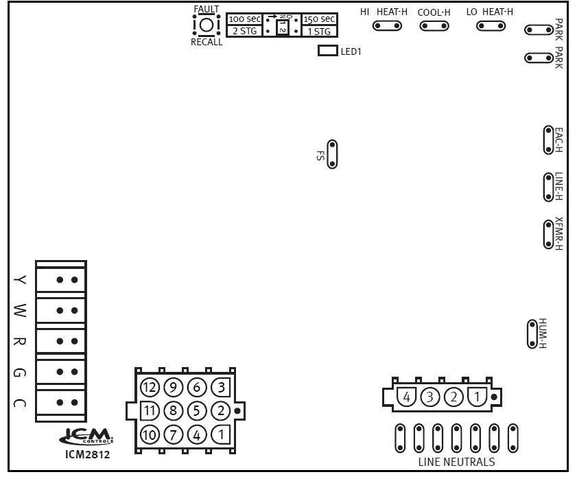
12-Pin Connections
- = Limit switch Out
- = Low gas valve
- = 24 VAC hot (R)
- = Pressure switch Out
- = Rollout switch Out
- = 24 VAC common (C)
- = Limit switch In
- = Earth ground
- = Gas valve common
- = Pressure switch In
- = Rollout switch In
- = High gas valve
4-Pin Connections
- = Inducer blower
- = Hot Surface Ignitor (HSI)
- = Inducer blower neutral
- = Hot Surface Ignitor (HSI) neutral
Note 1: For American Standard/Trane, York PCLU and York P3UR furnaces: Install the black wire labeled “10” from pin 5 to pin 11 of the 12-pin harness which is connected to the furnace.
Note 2: There are some Rheem/RUUD furnace models which performed flame sense differently. Please read the information below before testing the furnace.
Note 3: For Nordyne furnaces, ICM2812-KIT will only be compatible with 120VAC models.
- Rheem/RUUD furnaces without a separate flame sensor will require the purchase of a Rheem flame sensor kit (62-24044-71) to be wired to pin 7 of the 9-pin harness which is connected to the furnace.
- Rheem/RUUD furnaces with a separate flame sensor which is NOT routed through the 9-pin harness will require removal of the flame sensor wire from the existing connection and rewiring it to pin 7 of the 9-pin harness which is connected to the furnace.
- Rheem/RUUD furnaces which have a separate flame sensor already routed to pin 7 of the 9-pin harness will not require this modification.
Connect the other end of the furnace harness into the ICM2812 harness labeled “2”, connect the other end of this harness to the ICM2812 circuit board and connect the orange wire to the “FS” (flame sensor) terminal.
7313 William Barry Blvd., North Syracuse, NY 13212 www.icmcontrols.com


 Replacement Kit Instruction Manual")


