![]()
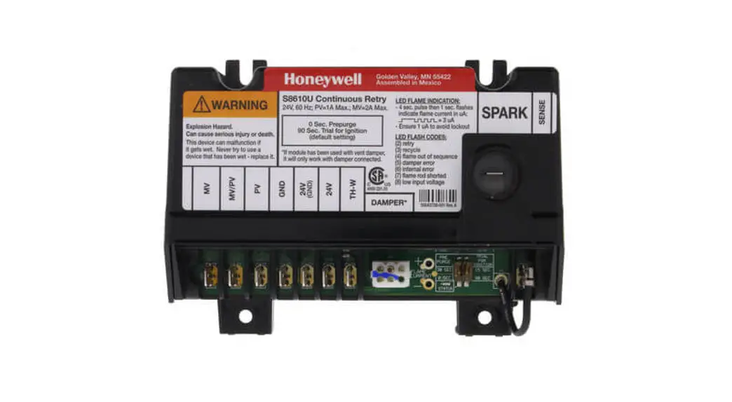
S8610U Universal
Intermittent Pilot Gas
Ignition Control
TECHNICIAN’S QUICK REFERENCE GUIDE
The following service procedure provides a quick overview for the S8610U series control. For more information, refer to form 69-1955.
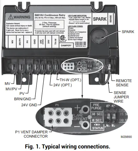

Table 1. Typical Wiring Connections.
| Connector Label | Size or Type | Description |
| MV | 1/4 inch | Main Valve connection |
| MV/PV | 1/4 inch | Common terminal for gas valves |
| PV | 1/4 inch | Pilot Valve connection |
| BRN GND | 1/4 inch | Burner Ground |
| 24V GND | 1/4 inch | Return path to the transformer |
| 24V | 1/4 inch | Optional- 24 Vac power connection for Vent Damper |
| TH-W | 1/4 inch | Connector for “Call for Heat” signal from the thermostat |
| P1 | 6-pin keyed plug | Connector for Vent connection (used to control a connected Samper Damper in atmospheric appliances) |
| METER (µA) | Ammeter probes | Connection for ammeter probes for measuring flame current in gAmp DC. |
| SENSE JUMPER WIRE | Wire with 3/16 inch quick connect | Connects to the REMOTE SENSE connector for installations with a single spark rod (local flame sensing) NOTE: For installation with remote flame sensing separate spark and sensor rods, this jumper wire is clipped as close to the circuit board as possible and the wire is discarded. |
| REMOTE SENSE | 3/16 inch | Flame Sensor connector For single rod installations, connect the SENSE JUMPER WIRE to this terminal connector. For dual rod installations, connect the flame sense wire from the burner/igniter to this terminal connector. |
| SPARK | 1/4 inch | High voltage sparking electrode |
SETTINGS AND ADJUSTMENTS
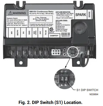
DIP Switch (S1) Settings
When replacing an existing ignition control with the S8610U, refer to 69-1955 for the correct DIP switch settings.
IMPORTANT
Do not power the ignition control prior to setting the DIP switches.
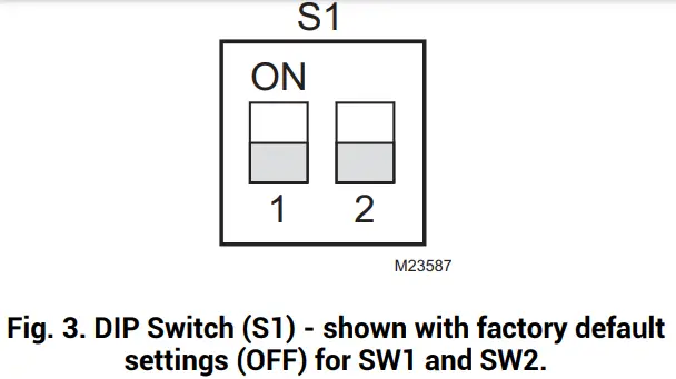
The following timing parameters may be set with this
2-position DIP switch.
Prepurge
To select Prepurge, set SW1 according to Table 2.
Trial for Ignition (TFI)
To select the Trial for Ignition timing, set SW2 according to Table 2.
Table 2. DIP Switch (S1) Settings.
| Prepurge | Trial For Ignition | SW1 | SW2 |
| None | 90 seconds | OFF | OFF |
| 30 seconds | 90 seconds | ON | OFF |
| None | 15 seconds | OFF | ON |
| 30 seconds | 15 seconds | ON | ON |
LED STATUS AND TROUBLESHOOTING
The ignition control module has one LED used for flame sensing and system status.
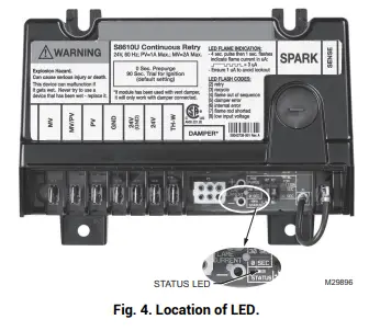
Table 3. Green LED Status Codes.
| Green LED Flash Cod? | Indicates | Next System Action | Recommended Service Action |
| 11 | No tall for Hear | Not applicable | None |
| F lash Fast | Power up – internal check | Not applicable | None |
| Heartbeat | Normal startup – ignition sequence started (including pre-purge) | Not applicable | None |
| 4 Seconds ON then V flashes | Device n run mode. ‘X’ . flame current to the nearest IAA. | Not applicable | None |
| 2 | 5-minute Retry Delay – Pilot flame not detected during trial for ignition | Initiate new trial for ignition after retry delay completed. | If the system fails to light on next trial for ignition check gas supply, pilot burner, spark and flame sense wiring flame rod contaminated or out of position, burner ground connects ion. |
| 3 | Recycle – Flame failed during nn | Initiate a new trial for ignition. Flash code will remain through the ignition trial until the flame is proved. | If system fads to light on next trial for ignition. check gas supply, pit burner, flame sense wiring, contamination of flame rod, burner ground connection. |
| Flame sensed out of sequence | If the situation self-corrects within 10 seconds, the control module returns to the normal sequence. If the flame out of the sequence remains longer than 10 seconds, the control will resume normal operation 1 hour after the error is corrected. | Check for pilot flame. Replace gas valve if plot flame present. If no plot flame, cycle ‘Cal for Hear If error repeats, replace control. | |
| 5 | Damper Error: – Damper required but not present – Damper faded to open within 60 seconds – Damper faded to close within 60 seconds | If damper error Corrects, ignition control resumes nonnalopera lion. | Check damper connection, damper our inn, and 24V connection on control. Replace the damper if necessary. |
| 6 | Control Internal Error | The control module remains in wart mode. When the fault corrects, the control module resumes normal operation. | Cycle ‘Call for Heat.’ If error repeats, replace control. |
| 7 | Flame rod shorted to ground | The control module remains in wait mode. When the fault corrects, the control module restrains normal operation. | Check flame sense lead wire for damage or shorting. Check that the flame rod is in the proper position. Check flame rod ceramic for cracks, damage, or tracking. |
| 8 | Low secondary voltage so la | The control module remains in wait mode. When the fault corrects, the control module resumes normal operation. | Check transformer and AC line for the proper input voltage to the control. Check with full system load on the transformer. |
aFlash Code Descriptions:
– Flash Fast: rapid blinking.
– Heartbeat: Constant ½-second bright, ½-second dim cycles.
– 4-second solid on pulse followed by “x” 1-second
flashes indicate flame current to the nearest mA. This is only available in run mode.
– A single flash code number signifies that the LED flashes X times at 2 Hz, remains off for two seconds, and then repeats the sequence.
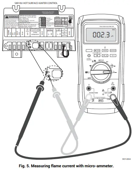
FLAME CURRENT MEASUREMENT
The flame current of the device can be measured using a standard micro-ammeter by simply inserting the meter probes into the holes labeled FLAME CURRENT, as shown in Fig. 5.
- The flame current must be measured with the pilot valve lit but no main gas flow.
- Disconnect MV lead wire from the control before measuring flame current.
- Set meter to DC μAmp scale.
- Ensure meter leads are positioned correctly [+/-].
NOTE: Trying to measure the pilot flame current in series with the wiring will not be accurate.
Recommended Minimum Pilot Only Flame Current:
- Must read steady 1 μAmp DC minimum.
- The flame current should be 2 μAmp or greater for reliable appliance operation.
![]() Resideo Technologies, Inc.
Resideo Technologies, Inc.
1985 Douglas Drive North, Golden Valley, MN 55422
1-800-468-1502
69-2042—01 M.S. 03-21 | Printed in the United States
© 2020 Resideo Technologies, Inc. All rights reserved.
This product is manufactured by Resideo Technologies, Inc. and its affiliates.
69-2042—01


