
BASO 24 Vac Intermittent Pilot Gas Ignition
Quick Reference Guide
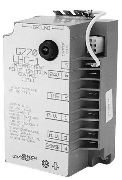
The Intermittent Pilot Gas Ignition Control module is designed for indirect burner ignition and supervision. It can be used in new applications or replaces many popular flame rectification type of intermittent pilot ignition (IPI) modules, including those manufactured by Honeywell, Robertshaw, ICM, Fenwal, and Johnson Controls.
The following is an overview of the control, and is intended to only be used by Certified Service Technicians.
APPLICATION 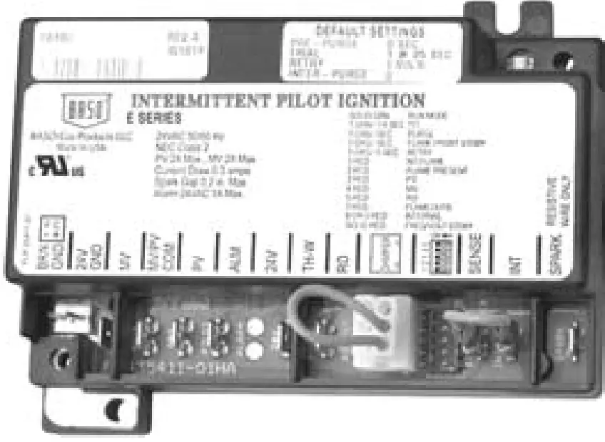
- Gas furnaces
- Boilers
- Water heaters
- Commercial cooking
FEATURES
- 24 VAC microprocessor based IPI control
- System diagnostics
- Flame sensing (Local/Internal or Remote/External)
- Full time flame sensing
- Flame sense test pins
- 4 mounting hole positions, 2 that match Honeywell and Fenwal
- Built-in burner ground
- Voltage/Frequency monitoring
SPECIFICATIONS
| Input Voltage | Control: 24 VAC (18-30VAC) 50/60 Hz |
| Input Current | 0.3 A nominal + valves |
| Gas Valve Contact Rating | 2A Pilot and 2A Main @ 24 VAC |
| Alarm Output | 2A @ 24 VAC |
| Operating Temperature | -40 to 176°F (-40 to 80°C) |
| Flame Detection Means | Flame Rectification |
| Flame Detection Type | Local/Internal or Remote/External |
| Minimum Flame Current | 0.07 microamperes |
| Flame Failure Response Time | 1.0 second maximum |
| Ignition Source | High voltage spark, capacitive discharge |
| Maximum Spark Gap | 0.2 in. (5.1 mm) |
| High Voltage Cable | 48 in. (1219mm) max., rated 15kV min. (Resistive recommended) |
| Flame Sense Cable | 48 in. (1219mm) max (Shielded recommended) |
| Spark | 30 sparks/second |
| Humidity | 0% to 95% RH (non-condensing) |
| Gas Types | Natural, LP, or Manufactured |
| Trials Before 100% Shutoff* | Preset 1, 3, Cont. |
| Trial for Ignition Time * | Preset 4, 8, 15, 30, 60, 90 seconds |
| Pre-Purge Time * | Preset 0, 15, 30 or 45 seconds |
| Inter-Purge Time * | Preset 0, 15, 30, 300, 360 seconds |
| Retry Delay Period * | Preset 0, 5, or 60 minutes |
| Lockout Recovery | Power cycle / Thermostat (TH-W) cycle |
For custom timings, contact BASO Gas Products.
AGENCY CERTIFICATIONS: UL 60370-1, UL 60730-2-5
File:M2926 Software Conforms to UL 60730 Requirement Component Recognized System (US & Canada)
WIRING
Table 1: Typical Wiring Connections.
| Label | Term. Type | Description |
| BRN GND | Mounting Tab | Burner Ground connection* |
| FC | 2 Pin | Flame Current measuring for microammeter probes in µAmp DC |
| 24V GND BRN GND | ¼” male QC | Common side (return) of transformer connection |
| MV | ¼” male QC | Main Valve connection |
| MV/PV COM | ¼” male QC | Gas Valve common terminal |
| PV | ¼” male QC | Pilot Valve connection |
| ALM | ¼” male QC | Alarm Signal |
| 24V | ¼” male QC | 24V Power Transformer connection |
| TH-W | ¼” male QC | Thermostat “Call for Heat” signal |
| RO | ¼” male QC | Roll-out connection |
| DAMPER P1 | 6-pin keyed plug | Vent Damper connection. Leave Vent Damper Jumper Plug installed if not a Vent Damper system |
| DIP SWITCH S1 | N/A | Not applicable on fixed timing ignitions. |
| SENSE | ¼” male QC | For dual rod (remote/external) flame sensing, connect the flame sense wire from burner/igniter to this terminal |
| INT | ¼” male QC | For single rod (local/internal) sensing, there will be no connection . |
| SPARK | ¼” male QC | High voltage sparking electrode |
If the existing system uses a burner ground wire, this can be attached to the 24V GND / BRN GND terminal using the supplied dual spade connector, or otherwise connected to the burner ground mounting tab.
Figure 1: Wiring for 1 Rod Flame Sense used for Local (Internal) Sense 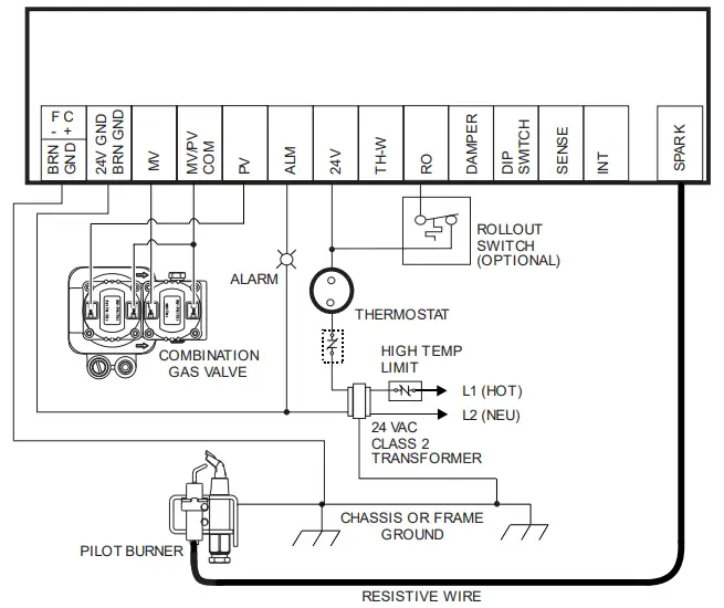
A rollout switch (a normally closed set of contacts) is positioned to detect flames rolling out of the combustion chamber. If rollout occurs, the switch contacts open and the control immediately goes into a lockout condition. The main and pilot valves also close so that the system is not allowed to function. A vent damper jumper plug that jumpers pins 2 and 3 of the damper connec-tion, is supplied with controls ordered with a vent damper system. The con-trol will operate normally with this plug in place, remove this plug to connect a vent damper. Once a vent damper has been connected to the control, and the power cycled, an internal fuse will blow* and the control can then only be used with a vent damper connected.
Note: it is normal to hear a defined pop when the fuse blows.
Figure 2: Wiring for 2 Rod Flame Sense used for Remote (External) Sense 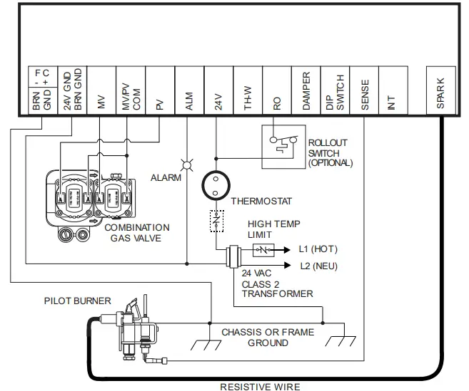
RESISTIVE WIRE
See notes on rollout switch and vent damper jumper plug on previous page.
Warning: Risk of explosion or fire. Do not install the control in an area that is exposed to water (ex. dripping, spraying or rain). Do not use the control if it has been exposed to water. Exposure to water may cause a malfunction and can lead to an explosion, which can lead to severe personal injury or death.
LED STATUS AND TROUBLESHOOTING
The ignition control has a multi-colored (GREEN, ORANGE, and RED) LED which will flash different colors and codes to show status of the ignition, and will help troubleshoot the control.
Table 3: GREEN LED Indications of Normal Operation
Flash
- On ½ sec, Off 4-½ sec
- On ½ sec, Off ½ sec
- On ¼ sec, Off ¼ sec
- On Solid
Indication
- Waiting for “Call for Heat”
- Pre-purge, Inter-purge,
- Post-purge Trial for Ignition (TFI)
- RUN (Flame, Pilot/Main valves on)
Table 4: ORANGE LED Indications
| Flash | Indication | ERROR Type |
| On ½ sec, Off 4-½ sec | Retry | Standby |
| On ½ sec, Off ½ sec | Flame present | Standby |
| On ½ sec, Off ½ sec | Pressure present | Standby |
Table 5: RED LED Indications of ERROR Codes (100% Lockout).
- Flash
- 1 flash
- 2 flashes
- 3 flashes
- 4 flashes
- 5 flashes
- 6 flashes
- 7 flashes
- 8 or 9 flashes Solid On
- Error Indications
- No flame in trial time
- Flame sense stuck
- Valve/Pilot relay circuit
- MV/Inducer circuit
- Rollout error
- Pressure switch
- Repetitive flame loss
- Internal control
- Line voltage/Freq.
- ERROR Type
- 100% Lockout
- 100% Lockout
- 100% Lockout
- 100% Lockout
- 100% Lockout
- 100% Lockout
- 100% Lockout
- 100% Lockout
- Standby
TROUBLESHOOTING GUIDE
Symptom
- No power up
- Faulty 24 VAC wiring
- Thermostat or transformer
- Faulty control
- Control LED is blinking RED
- Determine error code, refer to error codes (TABLE 5), also refer to the troubleshooting flow chart in the installation instructions
- No spark during Trial for Ignition (TFI) time
- Faulty spark electrode wiring
- Spark gap too wide
- Faulty control
- Pilot/Burner does not light during trial for ignition time
- Faulty valve wiring
- Bad Gas Valve
- Faulty control
- Pilot/Burner lights but Gas Valve turns off after TFI
- Weak flame, Flame not in contact with the spark electrode or flame sensor. Check that Flame Sensor tip is in the flame. For proper sensing the rod tip must be 3/8” (10mm) to 1/2” (13 mm) in the flame. See figure 1.
- Dirty or corroded flame sensor
- Faulty flame sensor wiring
- Poor burner ground
Note: For more information on BASO ignitions and other products, plus complete installation instructions, please visit us at www.baso.com.
Figure 1: Proper Flame Sensor position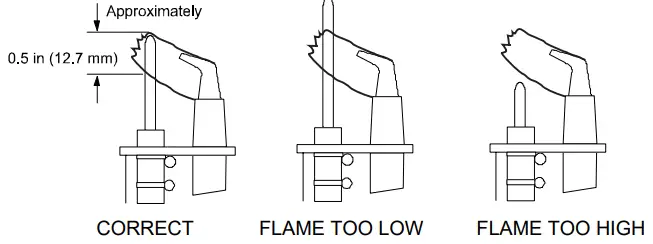
FLAME CURRENT MEASUREMENT
Flame current of the device can be measured using a standard micro-ammeter by simply touching the meter leads to the 2 PIN labeled FC, as shown in Figure 2.
- Flame current must be measured with pilot valve lit but no main gas flowing.
- Set meter to DC µAmp scale.
- Make sure meter leads are positioned correctly [+/-].
- Recommended Minimum Pilot Only Flame Sense Current of 0.8 µAmp DC.
Figure 2: Microammeter connection. 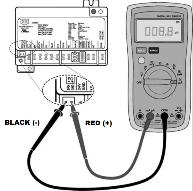
2 year warranty
BASO Gas Products
Part No. BASO-INS-E34, Rev. C


