![]()
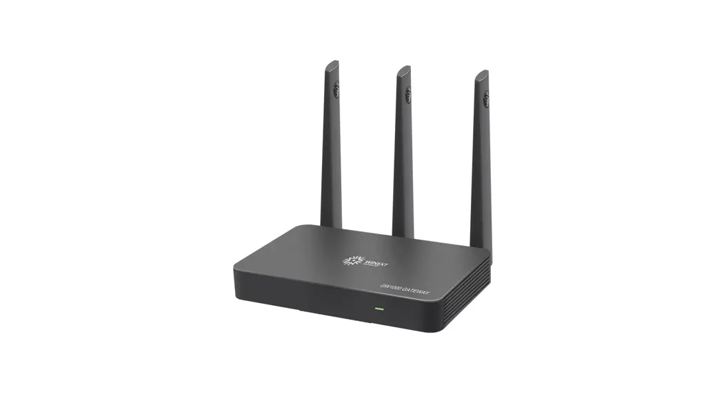
G200
USER MANUAL
PRODUCTOVERVIEWINTERFACE AND LEDs
1.1Brief Introduction
G200 Series gateway is a portable indoor gateway and complies with LoRaWAN™ protocol to provide low power, stable and secure wireless connectivity for devices and sensors. G200 adopts star topology deployment and provides WiFi or Ethernet connection to a network server. The solution is used in a wide area of applications such as smart energy, smart cities, and agricultural IoT. G200 meets the network requirements of long-range communications, strong anti-interference ability, high sensitivity, and low power for many dispersed nodes to provide a low-cost and high-reliability indoor IoT solution.
 1.2 Features
- Low Cost
Compact and portable, easy to install, cost-effective for LoRa network deployment. - Stable Network
The legal nodes can move freely within gateway coverage. When one gateway is abnormal in the multi-gateway network, the node can be accessed through an adjacent gateway. - Versatile BackhaulOptions
Support Ethernet/WiFi, support switch dynamically. - Easy Maintenance
Support remote troubleshooting and firmware upgrade, support local connection for debugging.
INTERFACE AND LEDs
2.1 Interface
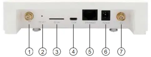
Port 1: LoRaAntenna (SMA-female)
Port 2: RESET
Port 3: SIMCard Slot
Port 4: MicroUSB
Port 5:Ethernet (RJ45)
Port 6: DC12V DC_IN
Port 7: WiFi Antenna(SMA-female)
NOTE: 1, Port 2: RESET hole, head into RESET hole with one end of paper clip for 6 seconds, then out. G200 restore factory defaults.
2.2 LED Status Indications
| LEDs | Function definition |
| Flash blue and green every 1 second | • Normal data forward • Normal data forward |
| Flash red and blue every 1 second | • Abnormal NS connection • Normal data forward |
| Flash red and green every 1 second | • Abnormal NS connection • Abnormal data forward |
| White lights up for 1 minute | Gateway power on, system initialization |
| Off | Gateway is not powered on |
SPECIFICATION
LoRa Parameters
| Frequency Band | 915MHz |
| Communication | LoRaWAN, Star Network |
| Modulation | Lora |
| Mode | Half-duplex |
| Sensitivity | -137dBm @SF12/13W 125KHz |
| Max Transmitter Power | 17 dBm (Typical) |
| Channel & Bandwidth | 125KHz/250KHz/500MHz Configurable |
| Interface | EthemetANiFi |
| Communication Distance | Suburban 5Krn, urban 3Km |
Physical
| IP Gracia | 1P30 |
| Size | 142mm”142mm*35mm |
| Color | Off white |
| Material | PC+ABS |
| Input Voltage | DC12V(11.0 VDC — 14.0 VDC) |
| Installation | Desktop/Wall mount/Ceiling mount |
| Operating Temperature | 0-60°C |
| Operating Humidity | 0-90%RH |
| Thermal Methods | Radiator grille |
Hardware
| Prnroccnr | MIPS 65MHz |
| RA | |
| Flash | 16MB |
| Vivi | QCA9513 |
Security System
| System Encryption | AES128 |
Remote Management
| Upgrade and Maintenance | Remote monitoring of network status |
| Support remote firmware upgrade. configuration backup and recovery |
CONFIGURATION
G200 provides a friendly and easy way to configure network parameters and LoRa parameters. After the configuration/modification is completed, you need to click the Save & Apply button at the bottom right of the page to save. After all the configuration/modifications are completed, you need to restart the gateway to take effect.
4.1 Getting Started
Please follow the steps below to log in: Step 1: Search AP ELI-G200-XXXXXX(XXXXXX is the last six hex number of G200 MAC) for G200, click connect, password:easylin kin.
Step 2: If the connection is successful, open browser (recommend IE browser) and input IP address: 192.168.3.1
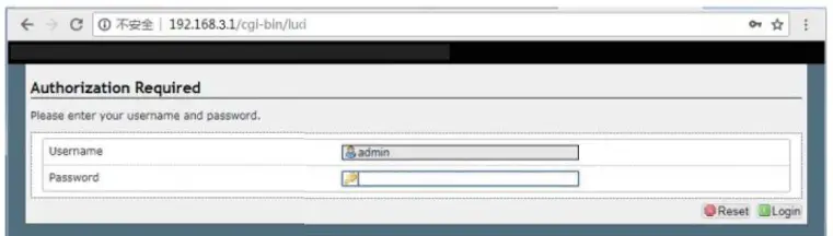
Step 3: After entering the login page, input your username, and password. Then enter the overview page, as shown below.
Username: admin (default)
Password: admin (default)
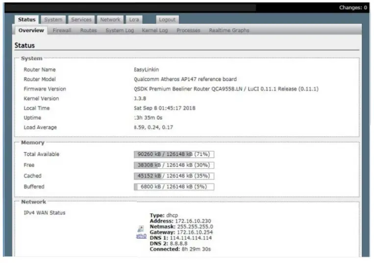
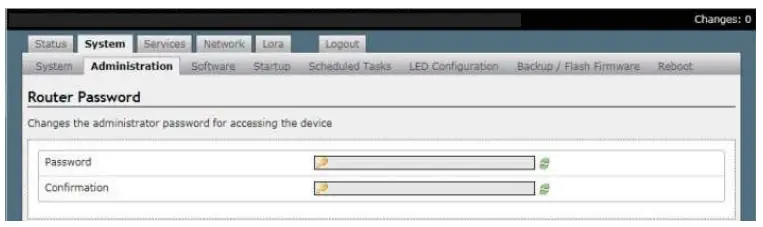
Status, System, Service, Network, LoRa, and Logout tabs are displayed at the top of the page. If you want to change the administrator password, please click System-Administration then input the new password and click Save & Apply.
4.2Modifying Network Parameters
Please follow the below steps to modify network parameters:
Step1: Click Network-Interface, then the Ethernet and WiFi configuration can be found in this page.
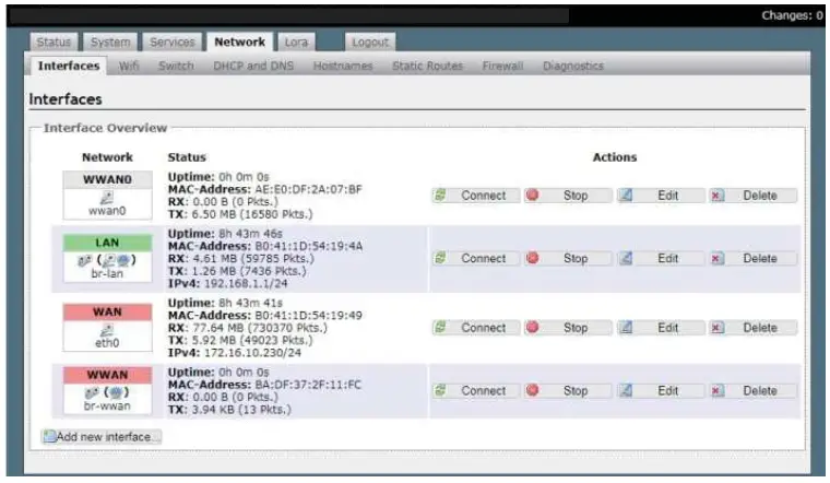
Step 2: Click WAN-Edit, the General Setup (Ethernet static IP configuration or DHCP configuration) can be modified. The default configuration is DHCP mode.
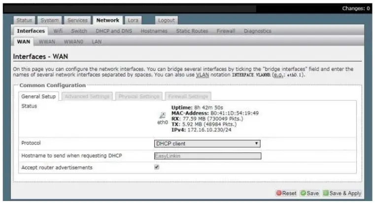
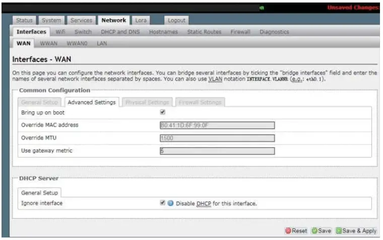
Step 3: The Use gateway metric needs to be configured to 5 during DHCP configuration.
Step 4: Set up the static IP address.
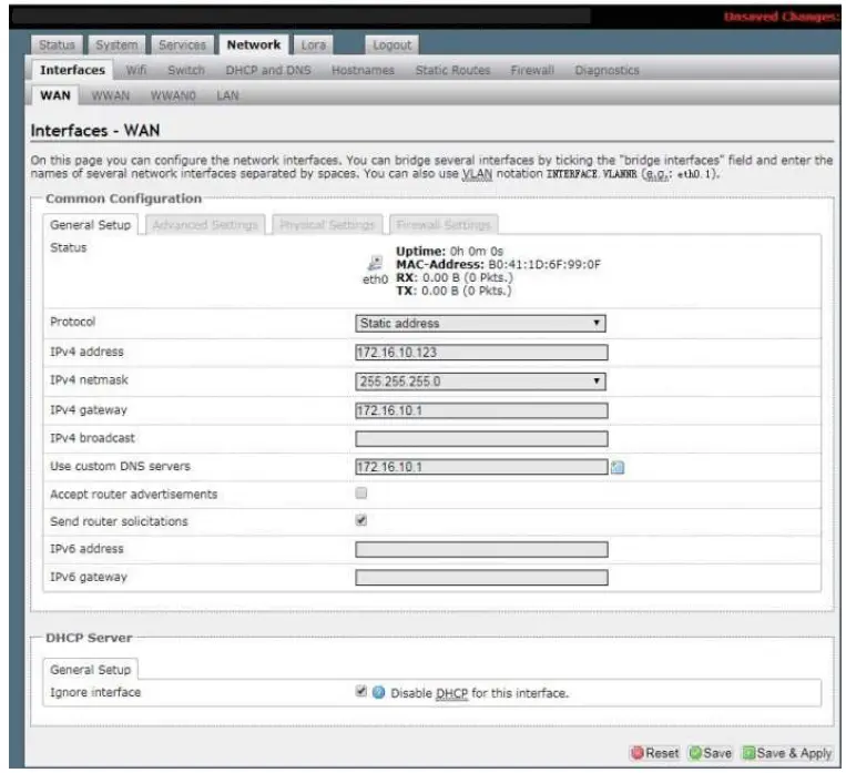
Note: If gateway connects to LinkWAN platform (that is NS from Ali cloud platform) .Set up the following DNS address: 223.5.5.5 or 223.6.6.6
Step 5:Click Save and Apply. The configuration is active.
Step 6:Step 4: Click Network-WiFi to enter the WiFi configuration page.
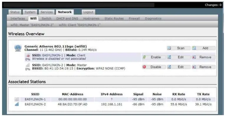
Step 7: Click Edit in the Client mode. The ESSID of the AP that will be connected can be set.
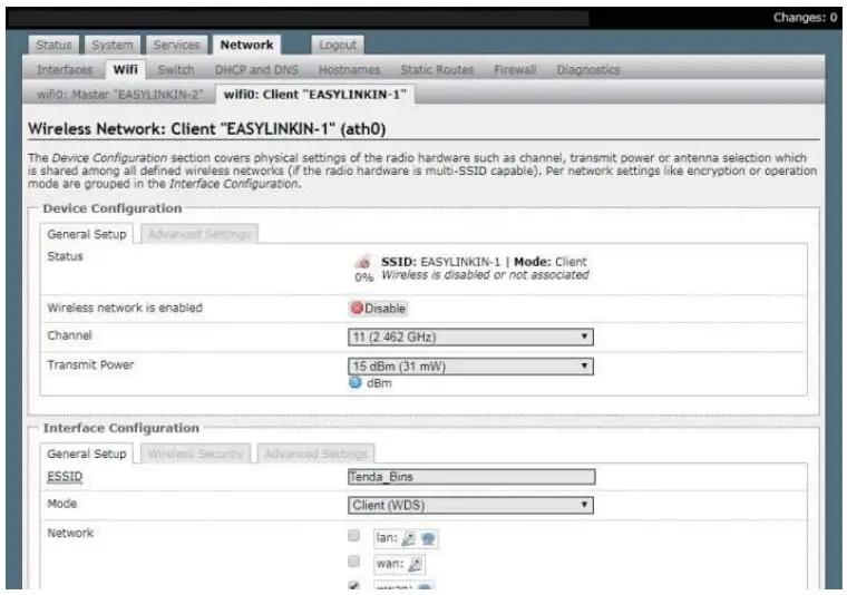
Step 8: Click Wireless Security, modify the key, then click Save & Apply to wait for connecting.
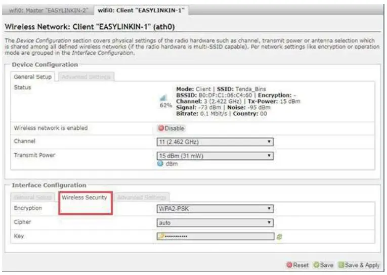
Step 9: If WiFi parameters modification is done, the AP connected and IPV4 address acquired can be displayed on the Associated Stationsin WiFi page.
NOTE: The Master mode is only used by technicians, so please do not do any modification under this model.
4.3Modifying LoRa Parameters
Please follow the steps below to modify LoRa parameters:
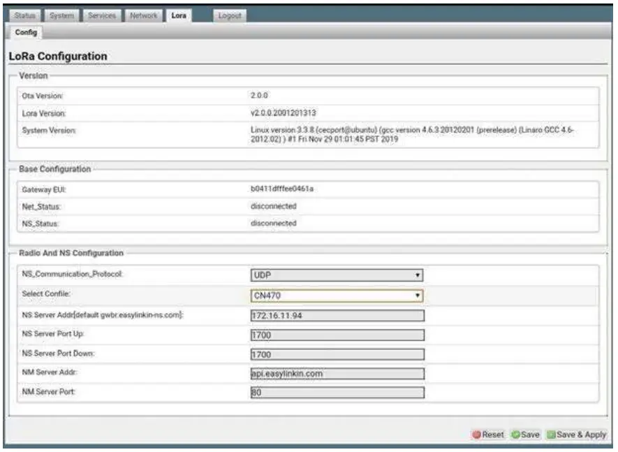
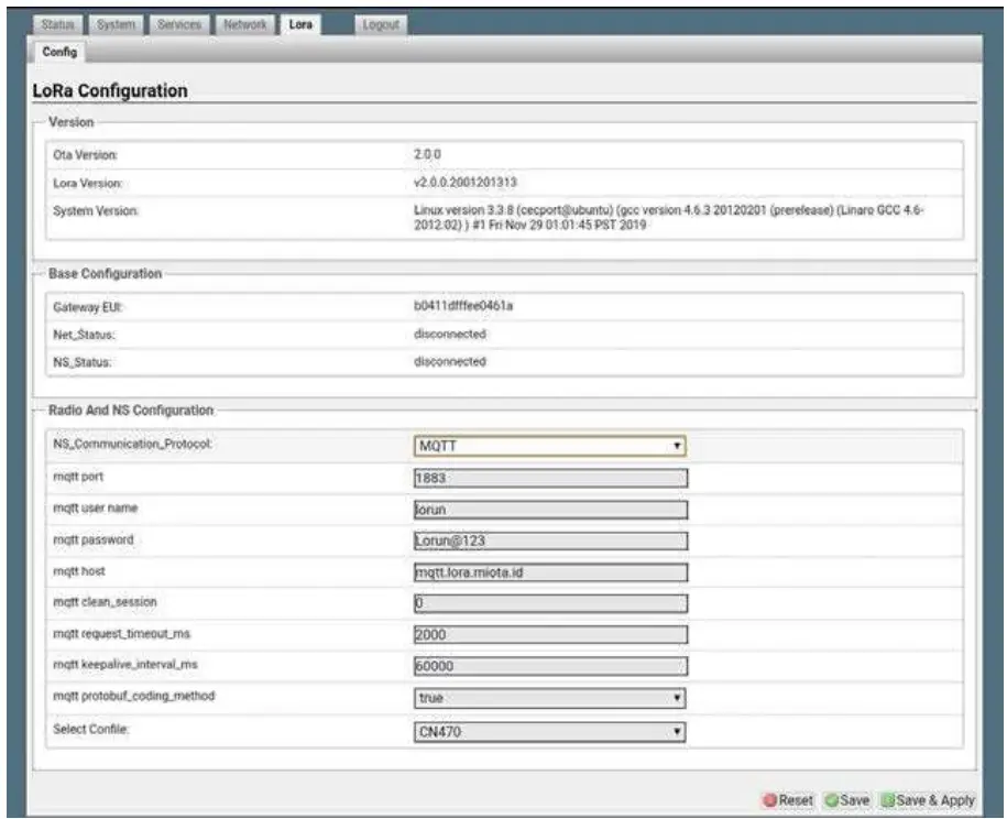
Step 1: Click LoRa on the overview page and enter the LoRa configuration page, which is composed of three parts: Version Configuration, Base Configuration, Radio, and NS Server Configuration.
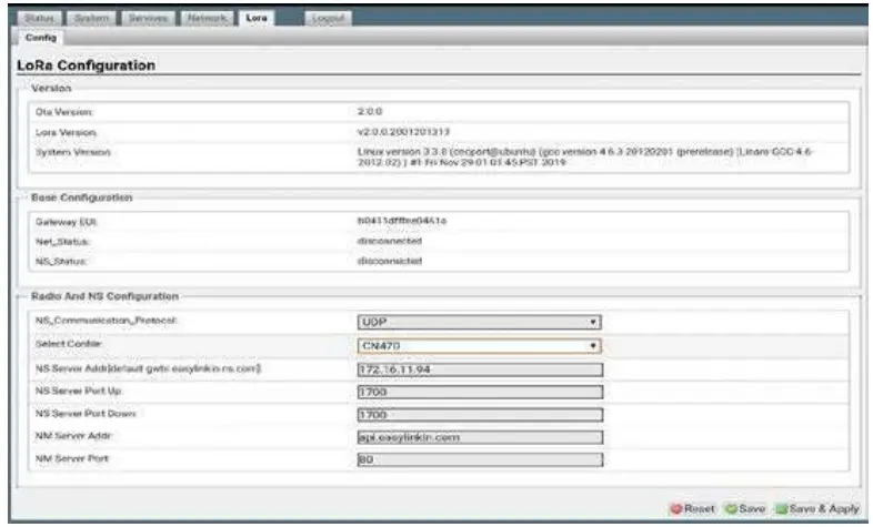
Step 2Gateway EUI can be shown in Base Configuration.
Step 3: Different LoRa frequency bands can be chosen in Radio Configuration.
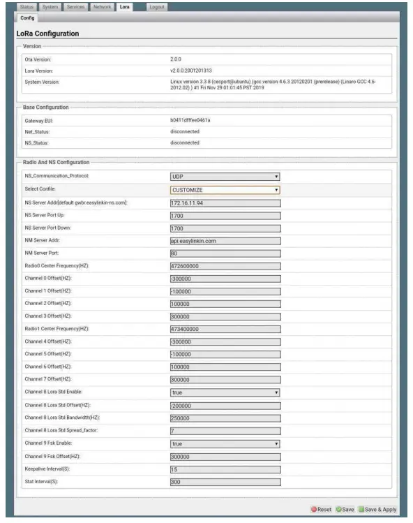
Step 4: In the radio and NS configuration column, UDP and MQTT communication modes are supported
In UDP mode, you can select the actual Lora band from the drop-down menu, and configure the DNS server address (default: 0 gear. easy linking-ns.com ), NS Server Port up( default:1700 )NS Server Port down( default:170 NM Server Addr(default: api.easylink.com, and NM Server Portdefault:80 )
In MQTT mode, you can configure the information of the MQTT proxy server.MQTT protbuf_coding_method is true for protobuf encoding and false for JSON encoding.
After configuration, click the Save & Apply button in the bottom right corner of the page.
Remarks
Only UDP mode can configure ns server address, and MQTT does not have this configuration item;
4.4Customized Configuration
MQTT mode:
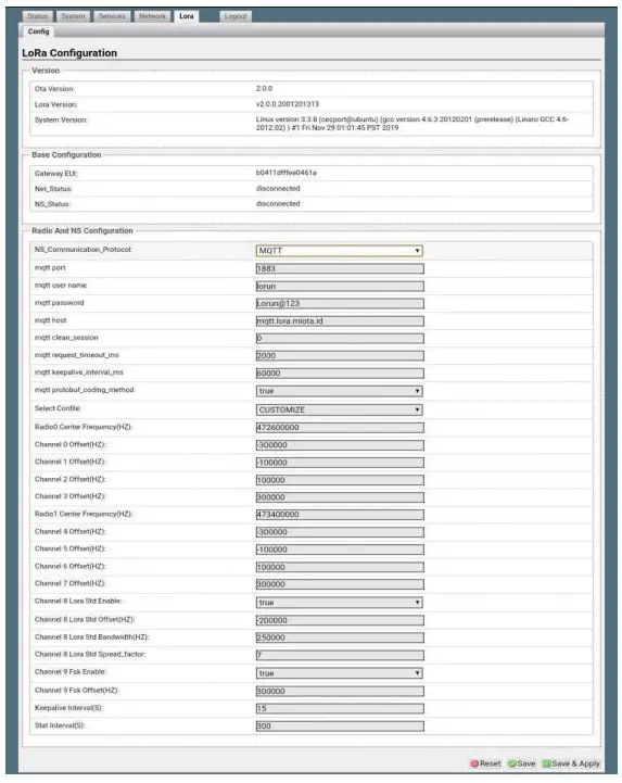
Step 2. Set up parameters as needed. For example, in keep-alive intervals, the frequency can be configured.
Step 3. After any modification, do not forget to click Save & Apply button.
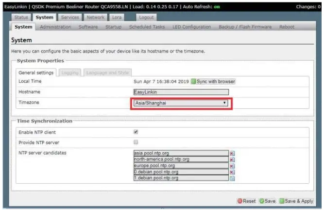
4.5Timezone Configuration
Step 1. Click System on the overview page and enter the System configuration page.
Step 2. Select the corresponding time zone as needed. If connect to the Ali LinkWAN platform, please choose UTC 0 time zone.
Step 3. After configuration, click Save & Apply to make the settings effective.
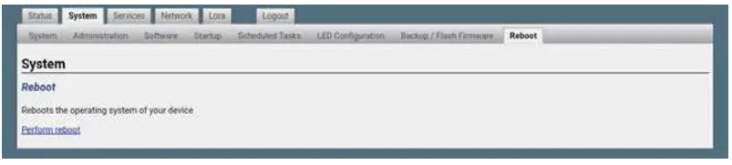
4.6Restart Gateway
After all configurations/modifications are completed, select System->Reboot, and click the Perform reboot button to restart the gateway. All configurations/modifications will take effect after the gateway restarts.
INSTALLATION
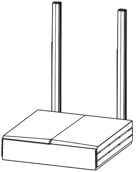
G200 Series gateway has three installation methods:
- Desktop: Put the gateway on a flat surface such as the top of a table. Then adjust antenna direction accordingly, which is suitable for temporary demonstration and debugging.
- Wall mounting: Attach the gateway on the wall with the installation kit to mount it using the expansion tube and the adjustable screws.
- Ceiling mounting: Attach gateway on the ceiling with an installation kit to mount it using an expansion tube and adjustable screws.
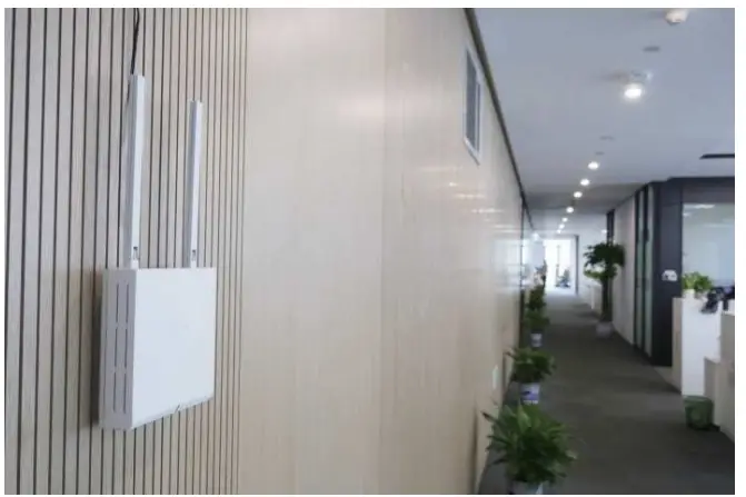
5.1WallMounting
Install the gateway packet:
Step 1:Select the installation position on the wall and mark the locations where the screw holes for the screws will be drilled.
Step 2: Drill holes (05) in the wall and plug-in plastic extension pipes (PA4.0*30mm), then place the gateway bracket onto the marked location with holes aligned.
Step 3: Tighten the screw.

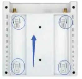
Place gateway into bracket:
Step 1: Connect WiFi/LoRa antennas.
Step 2: Connect the power adapter, connect the Ethernet cable. When the gateway is powered on, check the LED status. Make sure the gateway is working normally.
Step 3: Attach gateway to bracket, make the hook in the gateway align to the bracket grooves, push the gateway upward ( in a direction shown with a blue arrow ) and lock it to the bracket.
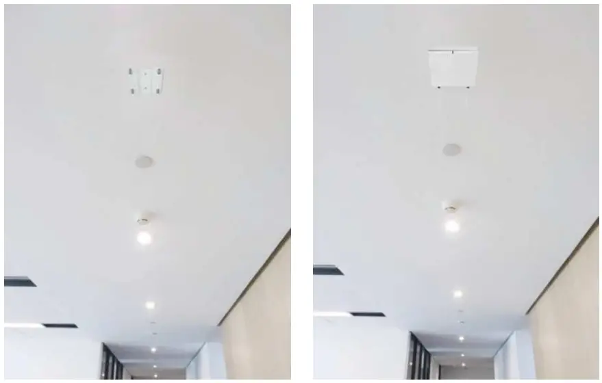
5.2Ceiling Mounting
Ceiling mounting is almost the same as wall mounting except that the bracket needs to be installed under the ceiling.
NOTES:
- The gateway should be handled gently without violent collisions and drops.
- The gateway should be mounted on a flat and dry surface with little dust and good ventilation. Do not expose the gateway to rain, water leakage, and any humidity.
PACKAGE LIST
| NO | Photo | Name | Quantity(PCS) | Note |
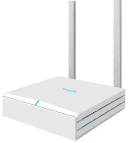
| 1 | 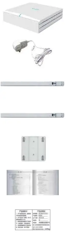 | G200 Gateway | 1 | |
| 2 | Power Adapter | 1 | FCC/U L/CE/CCC | |
| 3 | RF Antenna | 1 | ||
| 4 | WiFi Antenna | 1 | ||
| 5 | Bracket | |||
| 6 | Product Specification | 1 | ||
| 7 | Certificate & Warranty Card | 1 |
FCC STATEMENT
This device complies with part 15 of the FCC rules. Operation is subject to the following two conditions: (1) this device may not cause harmful interference, and (2) this device must accept any interference received, including interference that may cause undesired operation. Changes or modifications not expressly approved by the party responsible for compliance could void the user’s authority to operate the equipment.
NOTE: This equipment has been tested and found to comply with the limits for a Class B digital device, pursuant to part 15 of the FCC Rules. These limits are designed to provide reasonable protection against harmful interference in a residential installation. This equipment generates uses and can radiate radio frequency energy and, if not installed and used in accordance with the instructions, may cause harmful interference to radio communications. However, there is no guarantee that interference will not occur in a particular installation. If this equipment does cause harmful interference to radio or television reception, which can be determined by turning the equipment off and on, the user is encouraged to try to correct the interference by one or more of the following measures:
- Reorient or relocate the receiving antenna.
- Increase the separation between the equipment and receiver.
- Connect the equipment into an outlet on a circuit different from that to which the receiver is connected.
Consult the dealer or an experienced radio/TV technician for help with important announcements.
RF exposure warning: This equipment complies with FCC radiation exposure limits set forth for an uncontrolled environment. This equipment shall be installed and operated with a minimum distance of 20cm between the radiator & body.
SUPPORT
If you have any questions or problems with our gateway, please contact us for support.
EasyLink Address: Room 15D, 15th Floor, Microsoft Cogo Building,
Gaoxin South 5thRoad, Nanshan District, Shenzhen, China
Email: [email protected]
Tel: +86 0755 2692 5175


