![]() GWW1-M RAK7289 Westgate Edge Pro Outdoor Lora WAN Gateway
GWW1-M RAK7289 Westgate Edge Pro Outdoor Lora WAN Gateway
User Manual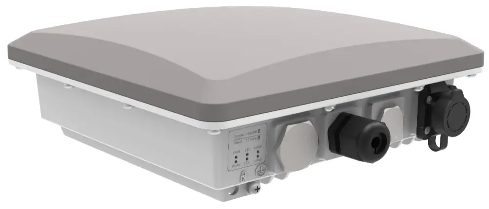
User manual for HAC-GWW1-M
Product description
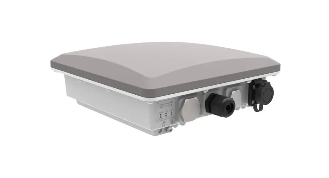
Westgate Edge is HACwireless flagship line of commercial-grade gateways. Customizable in terms of the backhaul connectivity options, antenna type, and power provisioning.
Westgate Edge Pro is an ideal product for IoT commercial deployment. With its industrial-grade components, it achieves a high standard of reliability.
Supports up to 16 Lora channels, multi-backhaul with Ethernet, Wi-Fi, and Cellular connectivity. Optionally there is a dedicated port for different power options, solar panels, and batteries. With its new enclosure design, it allows the LTE, Wi-Fi, and GPS antennas to be inside the enclosure.
The gateway provides a solid out-of-the-box experience for quick deployment. Additionally, since its software and UI sits on top of Openwork it is perfect for the development of custom applications (via the open SDK).
Manufacturers Address
Shenzhen HAC Telecom Technology Co., LTD
Floor 9, Block A, Building 1, Shenzhen International Innovation Valley, Xing 1st Street, Nanshan District, Shenzhen, China
Product specifications
2.1 Models
Main model: HAC-GWW1-M
2.2 Product Features
- Full Lora WAN Stack support in Built-In Server mode
- Supports 2.4 G Wi-Fi AP for configuration
- 100M Base-T Ethernet with Poe
- Power supply
– Poe (IEEE 802.3 aft), 37~57 VDC
– 12V/1A
– Support HAC Battery Plus - Ingress protection IP67
- Enclosure material – Aluminum and plastic
- Operating temperatures -30 ˚C to +55 ˚C
- Installation method Pole or wall mounting
- Multi back-haul with Ethernet and Wi-Fi
- Cellular LTE Cat 4 network (optional, available with C versions)
- BLE connectivity (optional, available with H versions)
- Openwork software supports Web UI for easy configuration and monitoring
- Can integrate with both private (e.g. Chirp Stack) and public (e.g. TTN) network servers
- SD card for system logs backup
- Built-in Network Server for easy deployment of applications and integration of gateways
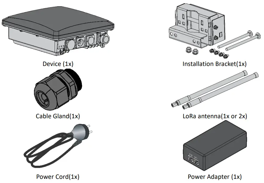
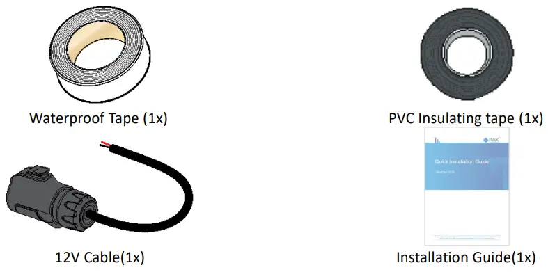
Packing List
Interfaces and connectors
The gateway’s interfaces and connectors are illustrated below:
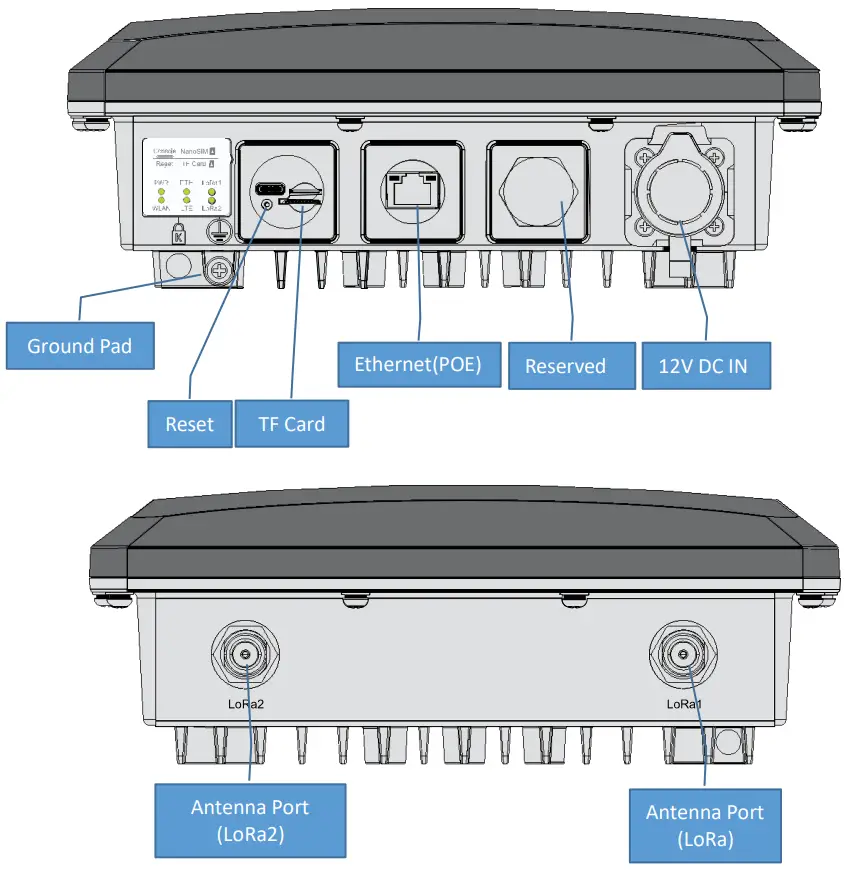
Note: the SD card and the SIM card do not support hot-swap. Please always turn off the gateway before you insert or take off SIM or SD card.
Note: Do not power the Gateway without a connected antenna/s. This may damage the radios.
Status LEDs
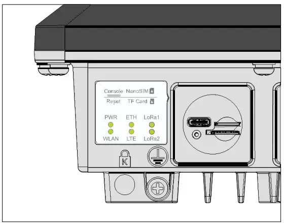
| Name | Status | Description |
| PWR ON/OF | F | • ON – device power on • OFF –device power off |
| ETH | ON/OFF/FLASH | • ON – link up • OFF – link down • Flash – Data Transmitting and Receiving |
| LoRa1 | ON/OFF/FLASH | • ON – LoRa1 is working • OFF – LoRa1 is not working • Flash – Indicate that LoRa1 Packet Transmitting and Receiving |
| LoRa2 | ON/OFF/FLASH | • ON – LoRa2 is working • OFF – LoRa2 is not working • Flash – Indicate that LoRa2 Packet Transmitting and Receiving |
| WLAN | ON/OFF/Slow FLASH/FLASH | • OFF-Wi-Fi disable AP Mode • ON – WLAN is working • Flash – Data Transmitting and Receiving STA Mode • Flash slowly (1Hz) – Connection Disconnected • ON – Connection Successful • Flash – Data Receiving and Sending |
| LTE | Flash slowly/ Flash quickly (Available for C model) | • Flash slowly 1 (200ms Bright/1800ms Dark)– Unregistered network (Network searching) • Flash slowly 2 (200ms Dark/1800ms Bright)– Idle status (online) • Flash quickly – Data Transmitting and Receiving |
Installation
Step 1: Fix the device bracket on the bottom of the enclosure with four M6*12 screws following the direction shown in the figure below.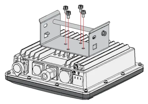
Step 2: Tighten the pole clamp bar with bolts, washer, and nuts.
Notes: The diameter of a pole that brackets support is 50-100mm. If the pole diameter is more than this value, the steel strips can be used. Standard delivery without steel strip and the user should purchase separately.
Step 3: Hang up the device and fasten it with two M6*12 Screws.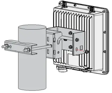
Connecting Power over Ethernet
Step 1: Connect the other end of the Ethernet cable from the enclosure to the Ethernet port labeled POE on the adapter.
Step 2: Connect an Ethernet cable from your LAN to the Ethernet port labeled LAN on the adapter.
Step 3: Connect the Power Cord to the power port on the adapter. Connect the other end of the Power Cord to a power outlet.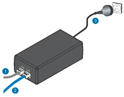
Weather protection
Tape sealed antenna and cable connections:
Step 1: to better protect the Ethernet cable gland and the antenna connector from the weather, you need to cover them with PVC tape.
Clean the surface area of the connector that will be wrapped. Wrap a layer of PVC tape with a 50% overlap according to the rotation direction of the connector. Continue wrapping the PVC tape to about 10 mm below the end of the connector.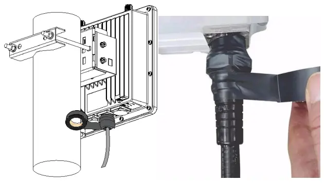
Step 2 Cut off about 50 cm waterproof tape. Stretch it to double the length. Wrap three layers around the connector with a 50% overlap. Hold the tape in place with your hand for a few seconds.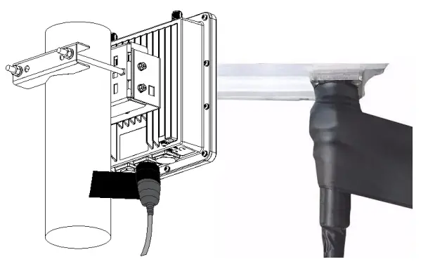
Step 3: Wrap three additional layers with PVC tape with natural uncoiling force and a 50% overlap. Make sure to cover the head and the tail of the connector. 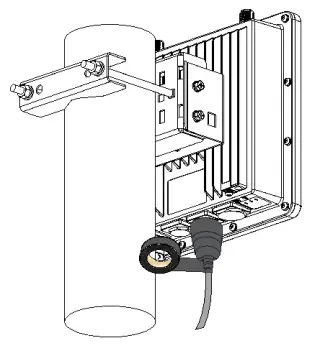
Accessing the gateway
WI-FI AP MODE
By default, the Gateway will work in Wi-Fi AP Mode which means that you can find an SSID named “HAC-GWW1-XM” on your PC’s Wi-Fi Network List. “XXXX” is the last two bytes of the Gateway MAC address. To access the Web Management Platform, input the IP Address: 192.168.230.1 in your Web browser.
NOTE
No password is required to connect via Wi-Fi
Using your preferred Web browser, input the aforementioned IP Address and you should see the same Log-in Page shown in the following image. Login with the credentials provided below:
- Username: root
- Password: root
For Westgate Edge Pro models V2 and H you need to set the login password at the first login.
WAN PORT (ETHERNET)
Connect the Ethernet cable to the port marked “ETH” on the Gateway and the other end to the Poe port of the Poe injector. Connect the LAN port of the Poe injector to your PC.
The default IP is 169.254.X.X. The last two segments(X.X) are mapped from the last four bits of the MAC address of your gateway. For example, the last four bits of the MAC address are 0F:01, and the IP address is 169.254.15.1. Make sure to manually set the address of your PC to one in the same network (for example 169.254.15.100). Use the same credentials for the Web UI as for AP mode.
Certification
CE
Operating frequency range
| Technology | Frequency band [MHz] | Maximum RF output power(dBm) | |
| Lora | 863-865, 865-868, 868-868.6, 868.7-869.2, 869.7-870 | 14 | |
| 869.4-869.65 | 27 | ||
| BLE | 2402-2480 | 10 | |
| WLAN 802.11 b/g/n | 2400-2483.5 | 20 | |
| GSM 900 | 880-915(TX),925-960(RX) | 33 | |
| GSM 1800 | 1710-1785(TX),1805-1880(RX) | 30 | |
| WCDMA Band I | 1920-1980(TX),2110-2170(RX) | 24 | |
| WCDMA Band VIII | 24 | ||
| LTE | Band 1 | 880-915(TX),925-960(RX) | 23 |
| Band 3 | 1920-1980(TX),2110-2170(RX) | 23 | |
| Band 7 | 1710-1785(TX),1805-1880(RX) | ||
| Band 8 | 2500-2570(TX),2620-2690(RX) | ||
| Band 20 | 880-915(TX),925-960(RX) | 23 | |
| Band 28A | 832-862(TX),791-821(RX) 703-733(TX),758-788(RX) | 23 | |
![]() Correct Disposal of this product. This marking indicates that this product should not be disposed of with other household wastes throughout the EU. To prevent possible harm to the environment or human health from uncontrolled waste disposal, recycle it responsibly to promote the sustainable reuse of material resources. To return your used device, please use the return and collection systems or contact the retailer where the product was purchased. They can take this product for environmentally safe recycling.
Correct Disposal of this product. This marking indicates that this product should not be disposed of with other household wastes throughout the EU. To prevent possible harm to the environment or human health from uncontrolled waste disposal, recycle it responsibly to promote the sustainable reuse of material resources. To return your used device, please use the return and collection systems or contact the retailer where the product was purchased. They can take this product for environmentally safe recycling.
FCC:
This device complies with Part 15 of the FCC Rules. Operation is subject to the following two conditions:
(1) this device may not cause harmful interference, and (2) this device must accept any interference received, including interference that may cause undesired operation.
FCC Caution:
Changes or modifications not expressly approved by the part responsible for compliance could void the user’s authority to operate the equipment.
This equipment has been tested and found to comply with the limits for a Class B digital device, pursuant to part 15 of the FCC Rules. These limits are designed to provide reasonable protection against harmful interference in a residential installation. This equipment generates, uses and can radiate radio frequency energy and, if not installed and used in accordance with the instructions, may cause harmful interference to radio communications. However, there is no guarantee that interference will not occur in a particular installation. If this equipment does cause harmful interference to radio or television reception, which can be determined by turning the equipment off and on, the user is encouraged to try to correct the interference by one or more of the following measures:
- Reorient or relocate the receiving antenna.
- Increase the separation between the equipment and receiver.
- Connect the equipment into an outlet on a circuit different from that to which the receiver is connected.
- Consult the dealer or an experienced radio/TV technician for help.
FCC RF Radiation Exposure Statement:
This equipment complies with FCC radiation exposure limits set forth for an uncontrolled environment. This equipment should be installed and operated with a minimum distance of 40cm between the radiator and any part of your body for HAC-GWW1-M![]()


