Milesight UG56 Industrial LoRaWAN Gateway
Safety Precautions
Milesight will not shoulder responsibility for any loss or damage resulting from not followingtheinstructions of this operating guide.
- The device must not be modeled in any way.
- Do not place the device close to objects with naked flames.
- Do not place the device where the temperature is below/above the operating range.
- Do not power on the device or connect it to another electrical device when installing.
- Check lightning and water protection when used outdoors.
- Do not connect or power the equipment using cables that have been damaged.
This Quick Start Guide only explains the installation of Milesight UG56 LoRaWAN® Gateway. For more functionality and advanced settings, please refer to the relevant documents as below.
| Document | Description |
| UG56 Datasheet | Datasheet for UG56 LoRaWAN® Gateway. |
| UG56 User Guide | Users can refer to the guide for instruction on how to log in the web GUI, and how to configure all the settings. |
The related documents are available on Milesight website: https://www.milesightiot.com
Declaration of Conformity
UG56 is in conformity with the essential requirements and other relevant provisions of the CE, FCC, and RoHS
For assistance, please contact
Milesight technical support:
Email: [email protected]
Tel: 86-592-5085280
Fax: 86-592-5023065

Revision History
| Date | Doc Version | Description |
| Aug.8, 2022 | V1.0 | Initial version |
Packing List
Before you begin to install the UG56 LoRaWAN® Gateway, please check the package contents to verify that you have received the items below.
- 1 × UG56 Device

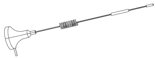
- 1 × LoRaWAN® Magnetic Antenna

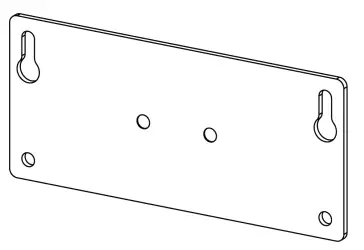
- 1 × Wall Mounting Bracket

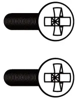
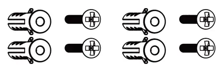
- 2 × M3 Bracket Fixing Screws

- 4 x Wall Mounting Kits

- 1 x Quick Start Guide

- 1 × Warranty Card

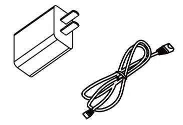
- 1 × Type-C Cable &Power Adapter (Optional)

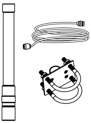
- 1 × LoRaWAN® Fiber-Glass Antenna Kit(Optional)


![]() If any of the above items is missing or damaged, please contact your sales representative.
If any of the above items is missing or damaged, please contact your sales representative.
Hardware Introduction
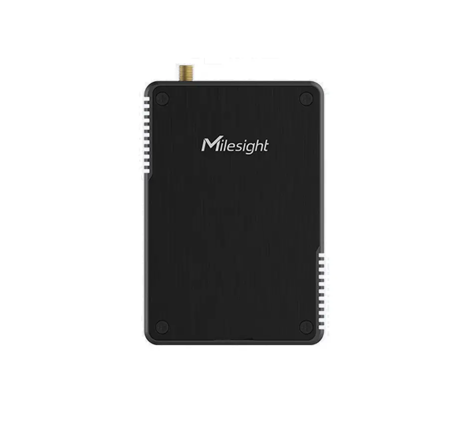
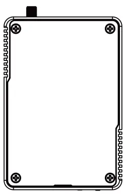
Overview
① LoRaWAN® Antenna Connector
② SIM Slot
③ Micro SD Slot
④ Reset Button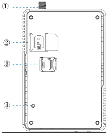
⑤ Type-C Power & Console Port
⑥ LED Indicators
⑦ Ethernet Port (PoE)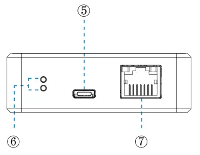
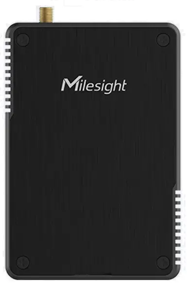
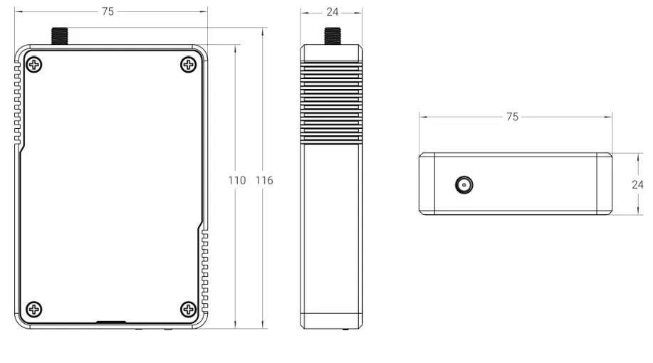
Dimensions (mm)
LED Indicators
| LED | Indication | Status | Description |
| SYS | System Status | Off | The system is starting up |
| Red Light | The system goes wrong | ||
| Green Light | The system is running properly | ||
| LoRa | LoRa Status | Off | Packet Forwarder mode is running off |
| On | Packet Forwarder mode is running well | ||
| Ethernet Port | Link Indicator (Yellow) | Off | Disconnected or connect failure |
| On | Connected | ||
| Blinking | Transmitting data | ||
| Rate Indicator (Green) | Off | Other modes | |
| On | 100 Mbps mode |
| Function | Description | |
| SYS LED | Action | |
|
Reset | Static Green | Press and hold the reset button for more than 5 seconds. |
| Static Green → Rapidly Blinking | Release the button and wait. | |
| Off → Static Green | The gateway resets to factory default. | |
Hardware Installation
SIM & Micro SD Installation
Remove the front panel of the device, insert the SIM card or micro SD card into the correspondingslot.
Note: UG56 does not support hot plugging (also called hot swapping). please turn off the power before you insert or take off cards.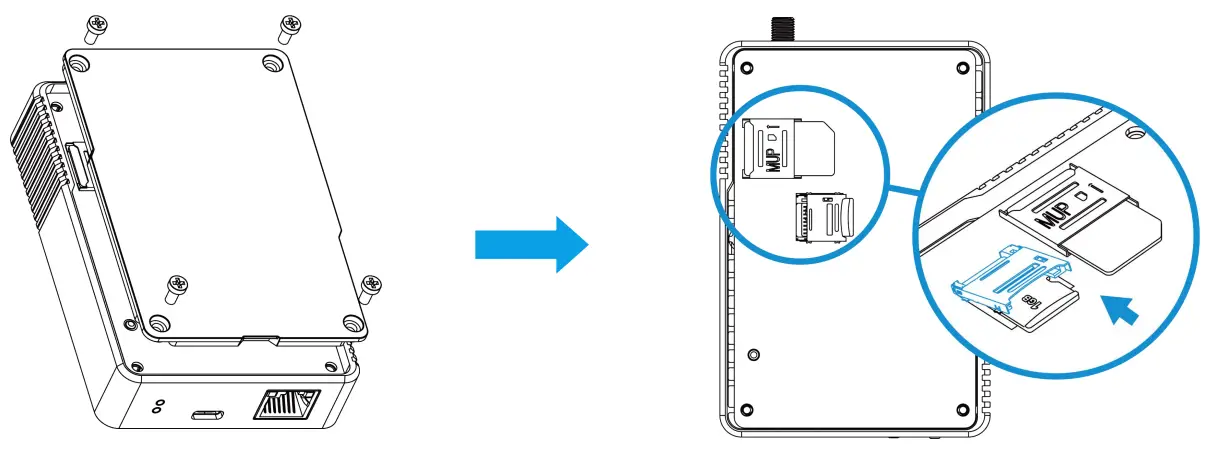
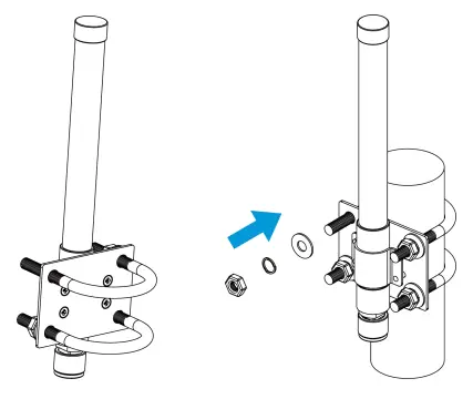
Antenna Installation
Rotate the LoRa antenna into the antenna connector. The antenna should be installed vertically and kepta way from batteries.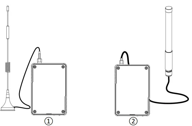
If you need to fix the LoRa fiber-glass antenna to a pole, please pass the LoRa antenna through the antenna clamp and fix it with 4 screws, then wrap the U-bolt around a pole and fix the clamp with nuts and other accessories.
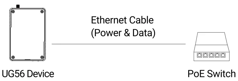
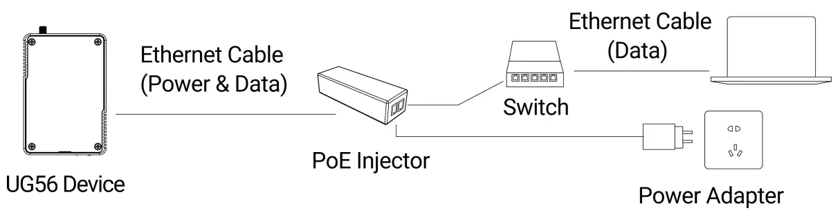
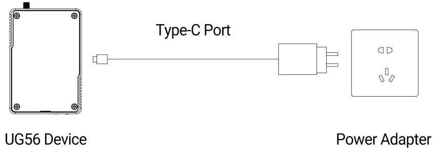
Power Supply
UG56 can be powered by 802.3af standard PoE or Type-C port (5 VDC). If both are connected, the device will be powered by the former method (PoE).
- Power by a PoE Switch

- Power by a PoE injector

- Power by a Type-C Port

Note: When connecting, Ethernet cable of UG56 device side should be installed first, otherwise, PoE devices or gateway may be damaged.
Gateway Installation
Before you get started, make sure all fittings are installed and the power supply is disconnected.
A. Fix the wall mounting bracket to the device with 2 x M3.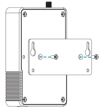
B. Drill 4 holes on the wall according to the wall mounting bracket, then fix the wall plugs into the wall.
C. Fix the device to the wall plugs with M3 wall mounting screws. When installation, it’s suggested to fix the upper two screws first.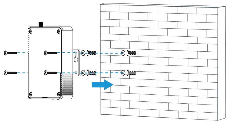
Web GUI Access
UG56 provides web-based configuration interface for management. If this is the first time you configure the gateway, please use the default settings below:
ETH IP Address: 192.168.23.150
Wi-Fi IP Address: 192.168.1.1
Wi-Fi SSID: Gateway_******
Username: admin
Password: password
Browser: Chrome(recommended)
Wireless Access
A. Enable wireless network connection on your computer and search for access point “Gateway_******”to connect it.
B. Open a web browser on your PC (Chrome is recommended) and type in the IP address 192.168.1.1toaccess the web GUI, enter the username and password, click “Login”.
![]() If you enter the username or password incorrectly more than 5 times, the login page will be locked for 10 minutes.
If you enter the username or password incorrectly more than 5 times, the login page will be locked for 10 minutes.
D. After logging the web GUI, follow the guide to complete the basic configurations. It’s suggested that you change the password.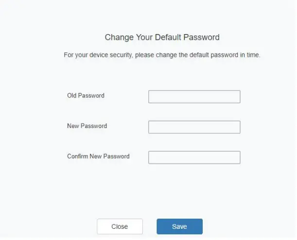
E. You can view system information and perform configuration of the gateway.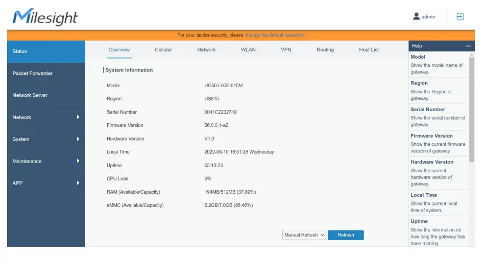
Wired Access
Connect PC to UG56 ETH port directly or through PoE injector to access the web GUI of gateway. The following steps are based on Windows 10 system for your reference.
A. Go to “Control Panel” → “Network and Internet” → “Network and Sharing Center”, then click“ Ethernet” (It may have different names).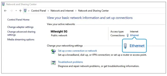
B. Go to “Properties” → “Internet Protocol Version 4 (TCP/IPv4) ”and select “Use the following IP address”, then assign a static IP manually within the same subnet of UG56.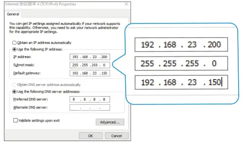
C. Open a Web browser on your PC (Chrome is recommended) and type in the IP address 192.168.23.150 to access the web GUI.
D. Enter the username and password, click “Login”.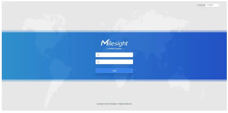
![]() If you enter the username or password incorrectly more than 5 times, the login page will be locked for 10 minutes.
If you enter the username or password incorrectly more than 5 times, the login page will be locked for 10 minutes.
E. After logging the web GUI, follow the guide to complete the basic configurations. It’s suggested that you change the password for the sake of security.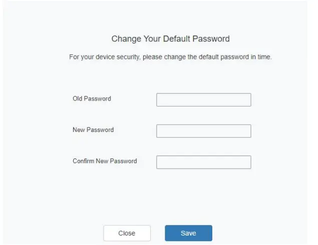
F. You can view system information and perform configuration of the gateway.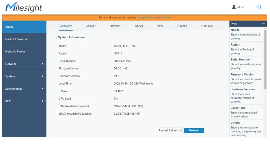
Network Connection
This section explains how to connect the gateway to network via WAN connection, Wi-Fi or cellular.
Configure the Ethernet Connection
A. Go to “Network”→ “Interface” → “Port” page to select the connection type and configure Ethernet port information.
B. Click “Save & Apply” for changes to take effect.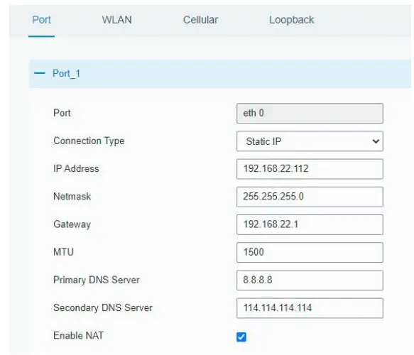
C. Connect Ethernet port of gateway to the devices like router or modem. D. Log in the web GUI via the newly assigned IP address and go to “Status” → “Network” to check Ethernet port status.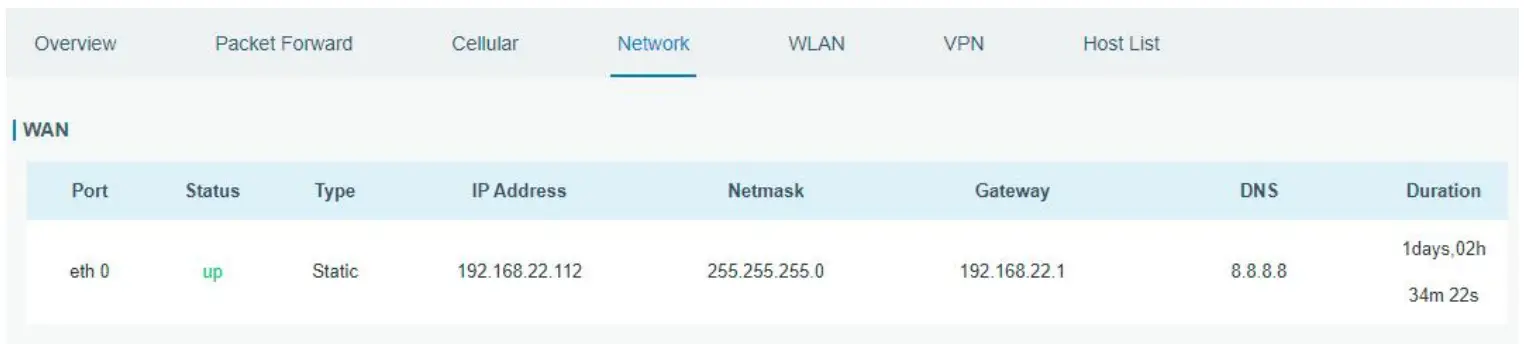
Configure the Wi-Fi Connection
A. Go to “Network” → “Interface” → “WLAN” and select “Client” mode.
B. Click “Scan” to search for Wi-Fi access points. Select the available one and click “Join Network”.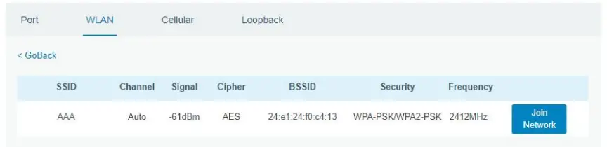
C. Type the key of Wi-Fi.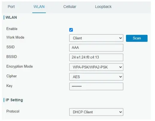
D. Go to “Status” → ”WLAN” to check Wi-Fi status. If it shows “Connected”, it means gateway connects to Wi-Fi successfully.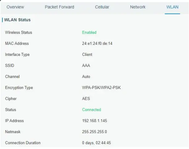
Configure the Cellular Connection
A. Go to “Network” → “Interface” → “Cellular” → “Cellular Setting” page to enable cellular settings.
B. Choose relevant network type and fill in SIM card information like APN or PIN code.
C. Click “Save” and “Apply” for changes to take effect.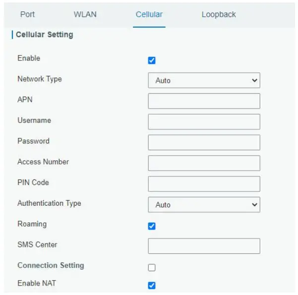
D. Go to “Status” → “Cellular” page to view the status of the cellular connection. If it shows “Connected”, it means the SIM has dialed up successfully. On the other hand, you can check the status of LTE indicator. If it keeps on light statically, it means SIM has dialed up successfully.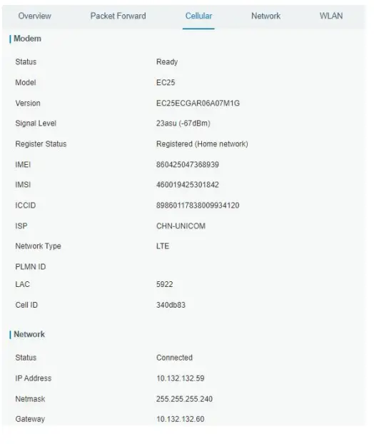
Packet Forwarder Configuration
UG has installed multiple packet forwarders including Semtech, Chirpstack Generic MQTT broker, etc. This section explains how to connect the gateway
![]() Make sure the gateway connects to the network as shown in Section 5.
Make sure the gateway connects to the network as shown in Section 5.
A. Go to “Packet Forwarder” → “General” page and click ![]() to add a network server.
to add a network server.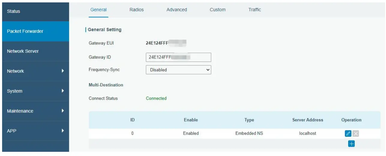
B. Fill in the server information and enable this server.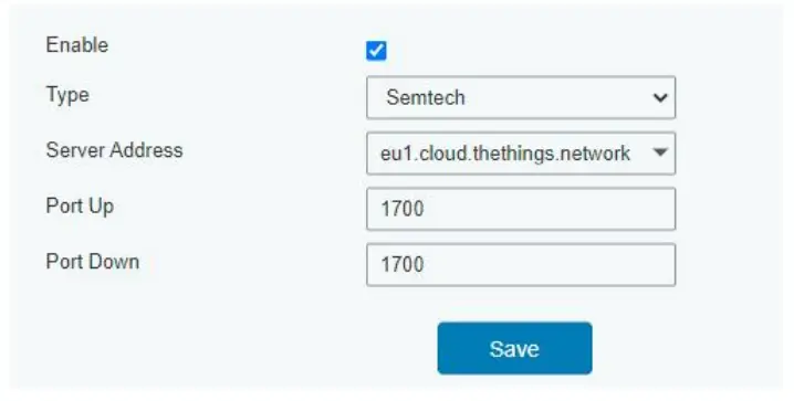
C. Go to “Packet Forwarder” → “Radio” page, center frequency and channels. The channels of the gateway and network server need to be the same.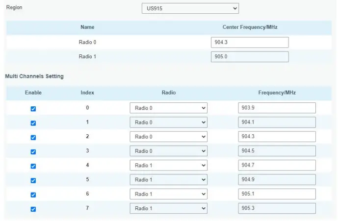
D. Add the gateway on network server page. For more details about the network server connection please refer to Milesight IoT Support portal.
E. Go to “Traffic” page to view the data communication of UG56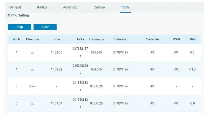
Network Server Configuration
UG56 can work as network server and transmit data to Milesight IoT Cloud or another platform via MQTT/HTTP/HTTPS.
![]() Make sure the gateway connects to the network as shown in Section 5.
Make sure the gateway connects to the network as shown in Section 5.
Connect UG56 to Milesight IoT Cloud
A. Go to “Packet Forwarder” → “General” page to enable the embedded network server.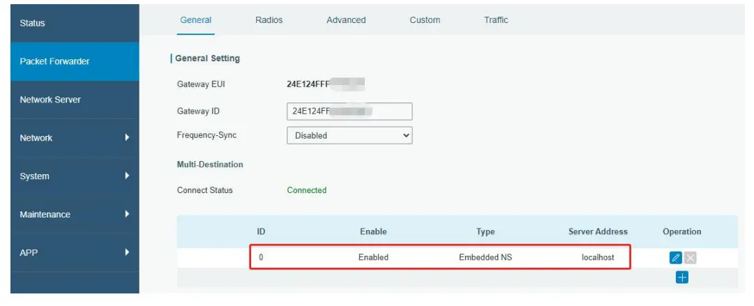
B. Go to “Packet Forwarder” → “Radio” page to select the antenna type, center frequency and channels. The channels of the gateway and nodes need to be the same.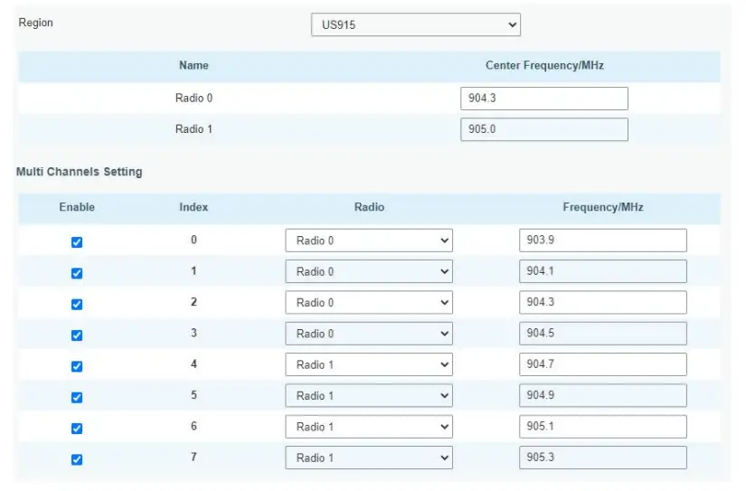
C. Go to “Network Server” → “General” page to enable the network server and “Milesight IoT Cloud” mode.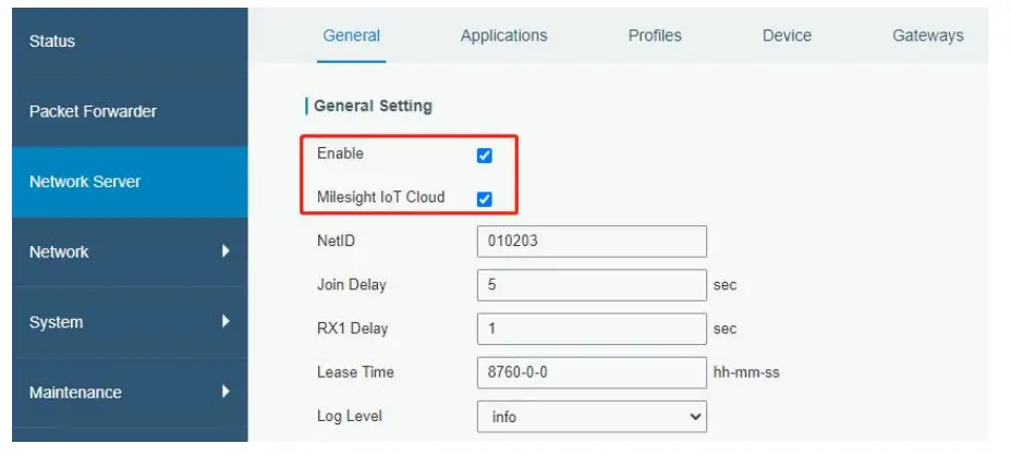
D. Log in the Milesight IoT Cloud. Then go to “My Devices” page and click “+New Devices” to add gateway to Milesight IoT Cloud via SN. Gateway will be added under “Gateways” menu.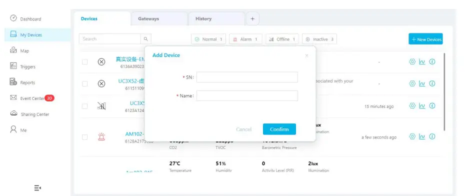
E. The gateway is online on Milesight IoT Cloud.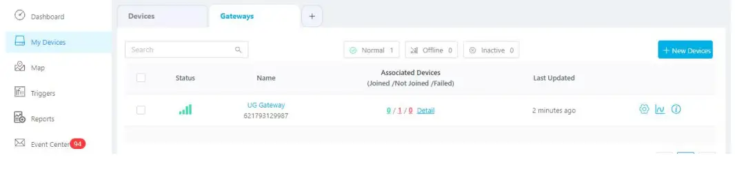
Connect UG56 to MQTT/HTTP Server
A. Go to “Packet Forwarder” → “General” page to enable the embedded network server.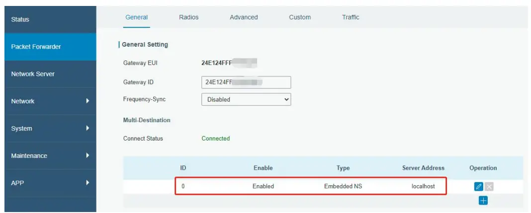
B. Go to “Packet Forwarder” → “Radio” page to select the antenna type, center frequency and channels. The channels of the gateway and nodes need to be the same.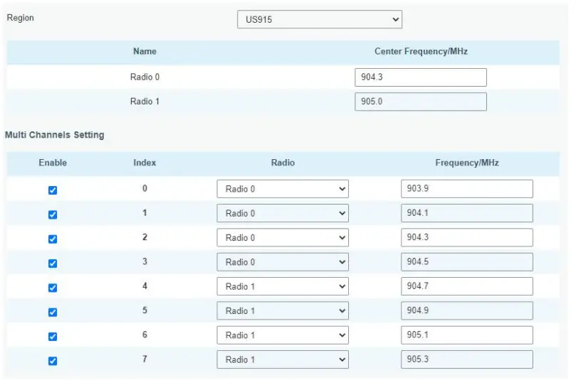
C. Go to “Network Server” → “General” page to enable the network server mode.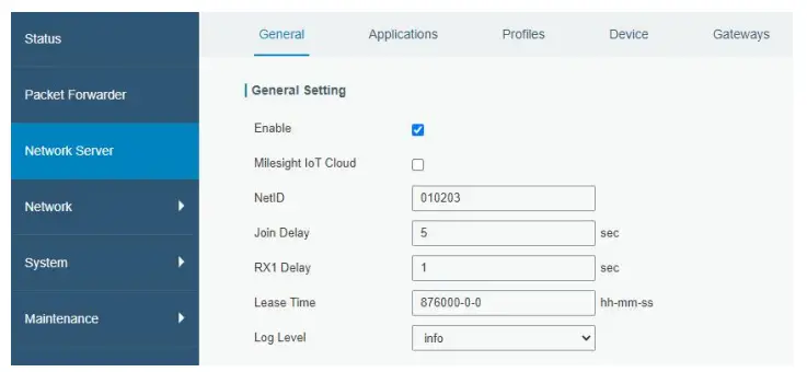
D. Go to “Network Server”→ ”Application” to add a new application.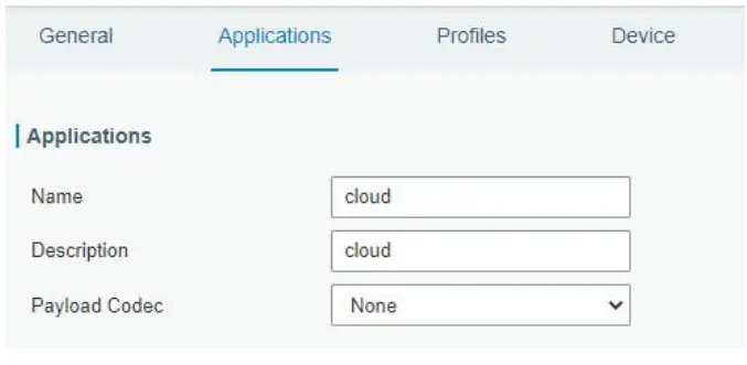
After saving the application, you can select HTTP, HTTPS or MQTT protocol and fill in corresponding server information to send data to another server.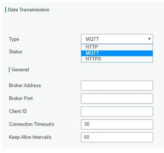
E. Go to “Profiles” page to add a new profile for the device.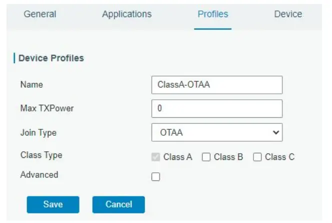
F. Go to “Device” page and click “Add” to add LoRaWAN® node devices.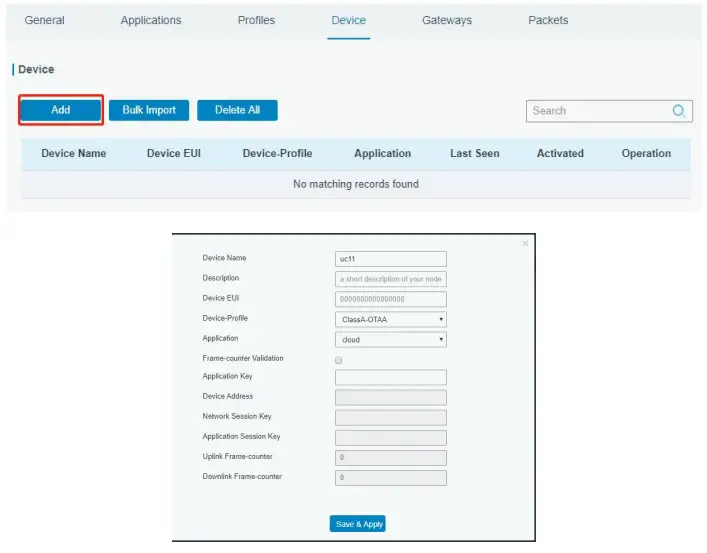
You can also click “Bulk Import” if you want to add many nodes all at once.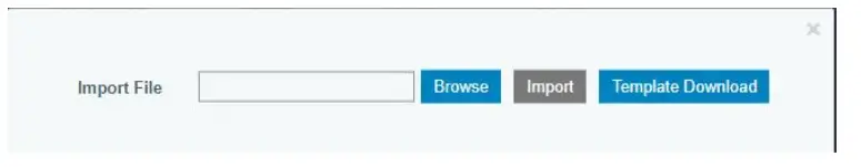
Click “Template Download” to download template file and add device information to this file. Application and device profile should be the same as you created on web page.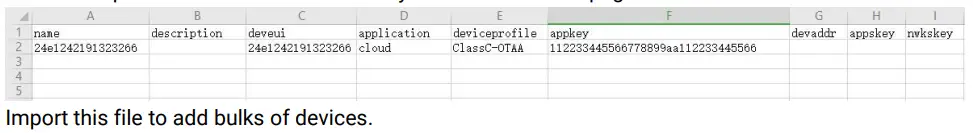
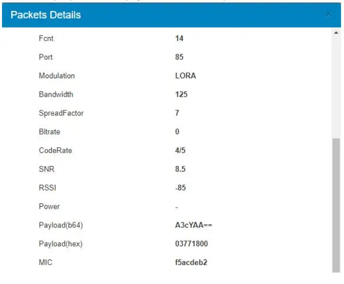
F. Go to “Packets” page to check the packets from LoRaWAN® node devices. The type starts from “Up” means uplinks and “Dn” means downlinks.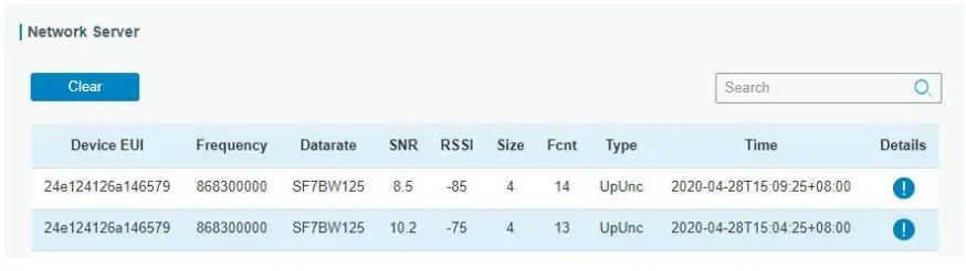
Click “Details” to check the properties and payload contents of packets.