
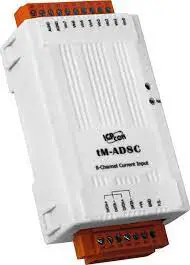
ICPDAS tM-AD8C 8 Channel Isolated Current Input Module
Congratulations on purchasing the tM-AD8C – the most popular automation solution for remote monitoring and control applications. This Quick Start Guide will provide information needed to get started with the tM-AD8C. Please also consult the User Manual for detailed information on the setup and use of the tM-AD8C.
INSIDE BOX
In addition to this guide, the shipping box includes the following items:
- tM-AD8C
 TECHNICAL SUPPORT
ICP DAS Website
Understanding the Hardware Specifications and Wiring Diagrams
Before installing the hardware, you should have a basic understanding of hardware specifications and the wiring diagrams.
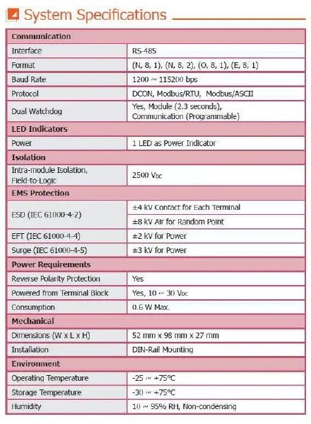
System Specifications:
 I/O Specifications:
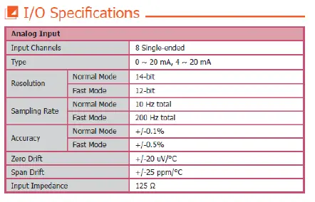 Wire Connection:
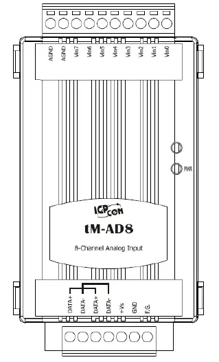
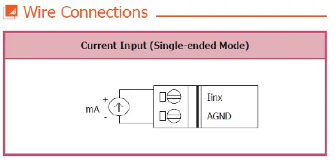 Pin Assignment:
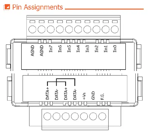
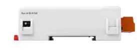
Booting the tM-AD8C in Init Mode
Make sure the switch placed in the “Init” position.
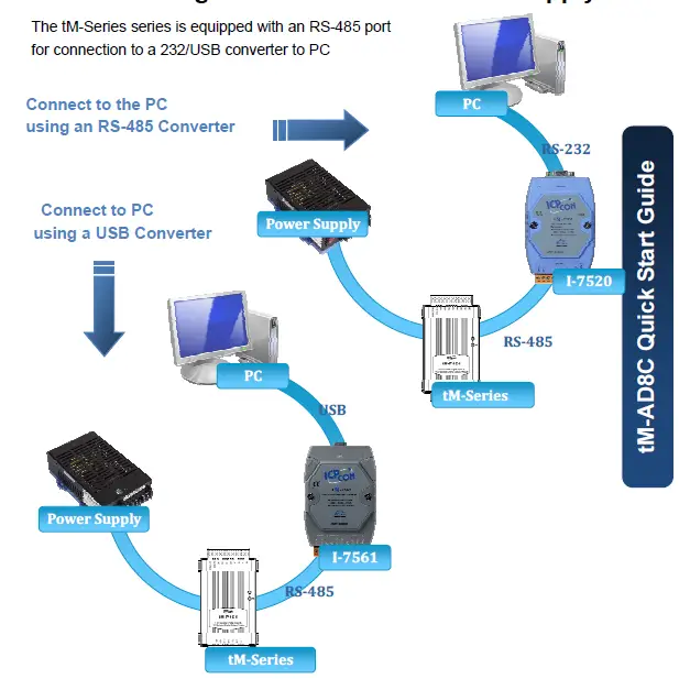
Connecting to the PC and the Power Supply
The tM-Series series is equipped with an RS-485 port for connection to a 232/USB converter to PC
Installing the DCON Utility
The DCON Utility is an easy-to-use tool designed to enable simple configuration of I/O modules that use the DCON protocol.
The DCON Utility can be obtained from the companion CD or from the ICPDAS FTP site:
CD:\Napdos\8000\NAPDOS\Driver\DCON_Utility\setup\
http://ftp.icpdas.com/pub/cd/8000cd/napdos/driver/dcon_utility/
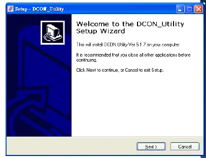
Step 2: Follow the prompts to complete the installation
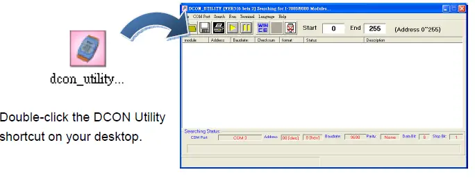
After the installation has been completed, there will be a new shortcut to the DCON Utility on the desktop.
Using the DCON Utility to Initialize the tM-Series Module
The tM-Series is an I/O module based on the DCON protocol, meaning that you can use the DCON Utility to easily initialize it.
Step 1: Run the DCON Utility
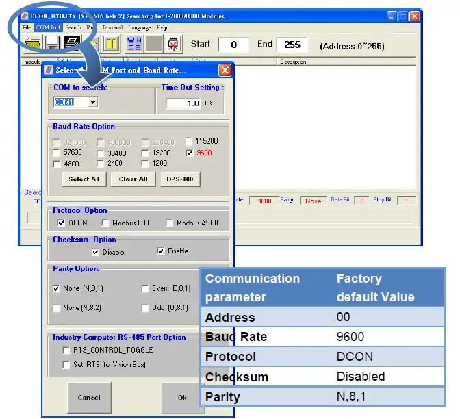
 Step 2: Use the COM1 port to communicate with the tM-Series
Click the “COM Port” option from the menu and a dialog box will be displayed that will allow you to set the communication parameters as described in the table below.
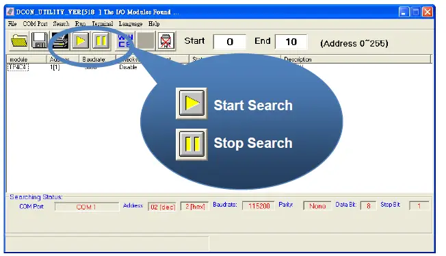
 Step 3: Search for the tM-Series module
 Step 4: Connect to the tM-Series
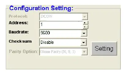
After clicking on the name of the module in the list, a dialog box will be displayed. 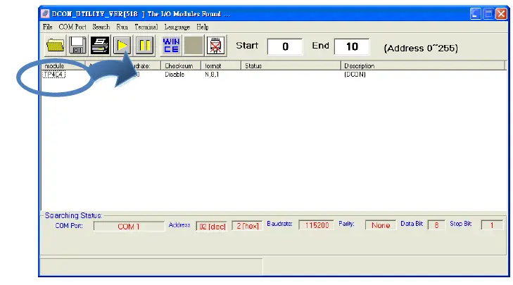 Step 5: Initialize the tM-Series module
Rebooting the tM-Series Module in Normal Mode
Make sure the INIT switch is placed in the “Normal” position.
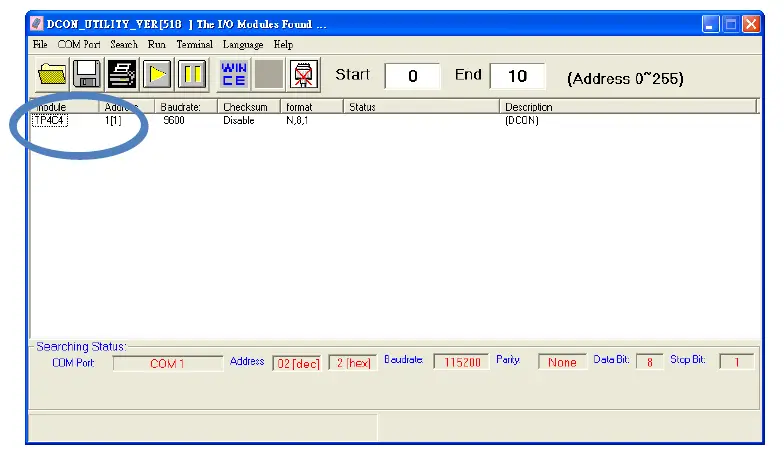
Starting the Module Operation
After rebooting the tM-Series module, search for the module to make sure the settings have been changed. You can double click on the name of the module in the list to open the configuration dialog box.
Modbus Address Mapping
| Address | Description | Attribute |
| 30001 ~ 30004 | Counter value of digital input | R |
| 40481 | Firmware version (low word) | R |
| 40482 | Firmware version (high word) | R |
| 40483 | Module name (low word) | R |
| 40484 | Module name (high word) | R |
| 40485 | Module address, valid range: 1 ~ 247 | R/W |
| 40486 | Bits 5:0 Baud rate, valid range: 3 ~ 10 Bits 7:6 00: no parity, 1 stop bit 01: no parity, 2 stop bit 10: even parity, 1 stop bit 11: odd parity, 1 stop bit | R/W |
| 40488 | Modbus response delay time in ms, valid range: 0 ~ 30 | R/W |
| 40489 | Host watchdog timeout value, 0 ~ 255, in 0.1s | R/W |
| 40492 | Host watchdog timeout count, write 0 to clear | R/W |
| 10033 ~ 10036 | Digital input value of channel 0 ~ 3 | R |
| 10065 ~ 10068 | High latched values of DI | R |
| 10073 ~ 10076 | High latched values of DO | R |
| 10097 ~ 10100 | Low latched values of DI | R |
| 10105 ~ 10108 | Low latched values of DO | R |
| 00001 ~ 00004 | Digital output value of channel 0 ~ 3 | R/W |
| 00129 ~ 00132 | Safe value of digital output channel 0 ~ 3 | R/W |
| 00161 ~ 00164 | Power on value of digital output channel 0 ~ 3 | R/W |
| 00193 ~ 00196 | Counter update trigger edge of channel 0 ~ 3 | R/W |
| 00513 ~ 00518 | Write 1 to clear counter value of channel 0 ~ 3 | W |
| 00257 | Protocol selection, 0: DCON, 1: Modbus | R/W |
| 00258 | 1: Modbus ASCII, 0: Modbus RTU | R/W |
| 00260 | Modbus host watchdog mode 0: same as I-7000 1: can use AO and DO command to clear host watchdog timeout status | R/W |
| Address | Description | Attribute |
| 00261 | 1: enable, 0: disable host watchdog | R/W |
| 00264 | Write 1 to clear latched DIO | W |
| 00265 | DI active state, 0: normal, 1: inverse | R/W |
| 00266 | DO active state, 0: normal, 1:inverse | R/W |
| 00270 | Host watchdog timeout status, write 1 to clear host watchdog timeout status | R/W |
| 00273 | Reset status, 1: first read after powered on, 0: not the first read after powered on | R |
Note: For tM DIO modules, Modbus registers starting at 00033 or 10033 can be used to read the digital input values. For M-7000 DIO modules, they are 00033 or 10001.
Copyright © 2009 ICP DAS Co., Ltd. All Rights Reserved. * E-mail: [email protected]


