V-TAC UK VT-4004E LED Batten Fitting Instruction Manual
TECHNICAL DATA
| Model | Waľľs | Color Temperaľure | Defaulľ S eľľing | Inpuľ Volľage | Lumens | S ize ( mm) | Microwave S ensor | E mergency Baľľery Backup |
| VT-4004E | 20W/30W/40W | 40W & | 5400LM | 1 1 70*65*70 | NO | Y E S | ||
| VT-4004SE | 4000K | Y E S | Y E S | |||||
| VT-4005E | 30W/40W/50W | 3000K/4000K/6500K | 50W &4000K | AC220-240V 50Hz. | 6750LM | 1 470*65*70 | NO | Y E S |
| VT-4005SE | Y E S | Y E S | ||||||
| VT-4006E | 40W/50W/60W | 60W & | 8100LM | 1 770*65*70 | NO | Y E S | ||
| VT-4006SE | 4000K | Y E S | Y E S |
SENSOR SPECIFICATION
| Operaľing Volľage | Microwave Frequency | Microwave Power | Operaľing Currenľ | IP Raľing | Conľrol Mode | Sľand-by Dimming level | Sľand-by Period | Hold Time | Daylighľ Threshold | Deľecľion Range | Deľecľion Angle |
| DC 7.5-12V | 5.8 HGz + 75 MHz | < 0.3mW | < 30mA | IP 20 | PWM | 0%/20% | 15 mins/+∞ | 5s/1 min/ 3 min/10 min | 30 Lux/ Disable | 12M(Max) | Side Wall < 50⁰ Ceiling Mounľ 360⁰ |
EMERGENCY SPECIFICATION
| Baľľery Type | Baľľery Capaciľy | Baľľery Volľage | Baľľery Charge Volľage | Baľľery Currenľ | Baľľery Discharge Volľage | Baľľery Discharge Currenľ | Charging Time | Operaľion Time | Tesľ Funcľion |
| LiFePO4, 18730. | 2000mAh | 6.4V | DC 9V | 30~400mA | DC 6.0~8.2V | 350~700 mA | > 12H | > 3H | Manual |
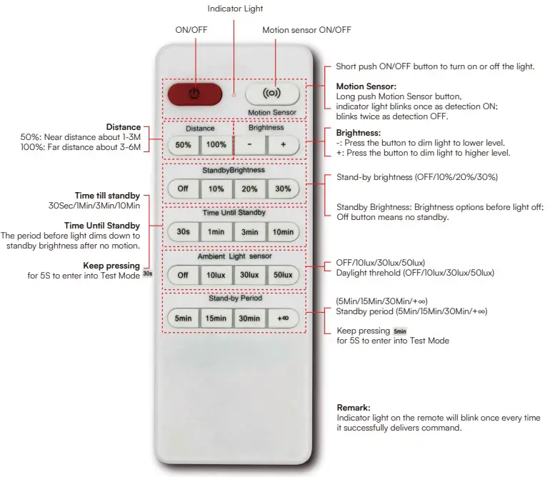
REMOTE CONTROL
| Baľľery | Deľecľion Area | Sľand-by Dimming Level | Sľand-by Period | Hold Time | Daylighľ Threshold | Brighľness Adjusľ |
| 2xAAA(Noľ included) | 50%/100% | 0%/10%/20%/30% | 5 min/15 min/30 min /+∞ | 30s/1 min/ 3 min/10 min | 10 Lux/30 Lux/50 Lux/Disable | -/+ buľľon on remoľe |
INTRODUCTION & WARRANTY
Thank you for selecting and buying V-TAC product. V-TAC will serve you the best. Please read these instructions carefully before starting the installation and keep this manual handy for future reference. If you have any another query, please contact our dealer or local vendor from whom you have purchased the product. They are trained and ready to serve you at the best. The warranty is valid for 3 years from the date of purchase. The warranty does not apply to damage caused by incorrect installation or abnormal wear and tear. The company gives no warranty against damage to any surface due to incorrect removal and installation of the product. The products are suitable for 10-12 Hours Daily operation. Usage of product for 24 Hours a day would void the warranty. This product is warranted for manufacturing defects only.
WARNING!
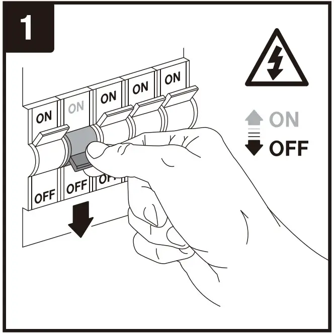
- Please make sure to turn off the power before starting the installation.
- Installation must be performed by a qualified electrician
- The light source of this luminaire is not replaceable, when the light source reaches its end of life the whole luminaire should be replaced.
- If the external flexible cable or cord of this luminaire is damaged, it shall be exclusively replaced by the manufacturer or his service agent or a similar qualified person in order to avoid a hazard.
- Proper grounding should be ensured throughout the installation.
- Please do not install on a surface that is prone to vibrations.
- Contact our customer support team for battery replacement.
- For Indoor use only [IP20].

This marking indicates that this product should not be disposed of with other household wastes.
 Caution, risk of electric shock.
Non-replaceable light source
Non-replaceable control gea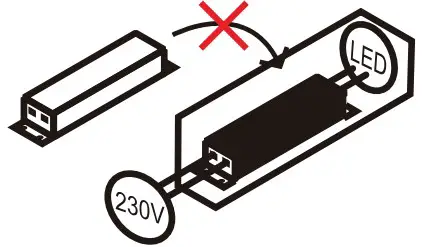
MULTI-LANGUAGE MANUAL QR CODE
Please scan the QR code to access the manual in multiple languages
INSTALLATION PRECAUTIONS
- Microwave sensor can be installed in any lamp except the one with full metal shell.
- The detected surface cannot be shielded by metal objects.
- Make sure the microwave module is completely exposed outside.
- The detection surface of the sensor module shall be installed facing the detection area.
- Should be kept away from the driver to avoid interference generation and lamp flashing.
- Wiring must be strictly in accordance with the wiring diagram to avoid short circuit.
USER NOTES
- 3M distance is suggested when having a lot sensors in one same room.
- If the sensor is applicated in the room with 5G WiFi router, 3M distance or above is needed
INSTALLATION DIAGRAM

INSTALLATION INSTRUCTIONS
- Switch OFF the power before starting the installation.
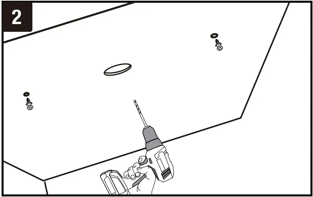
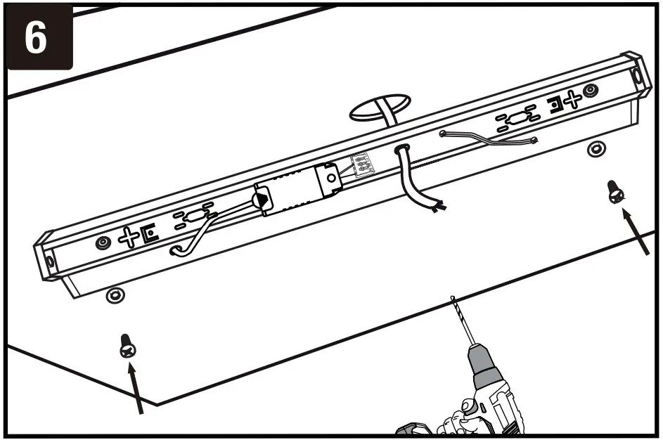
- Drill holes on the wall/surface using the fixing points or BESA plates for conduit mounting.
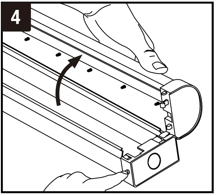
- Press the sides of the base and gently remove the front cover.
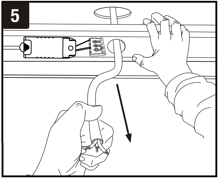
- Install plastic plugs into the drilled holes. Feed the cable from the backside of the fitting as shown in the diagram. Using the screws install the backside of the fitting on the wall/surface.
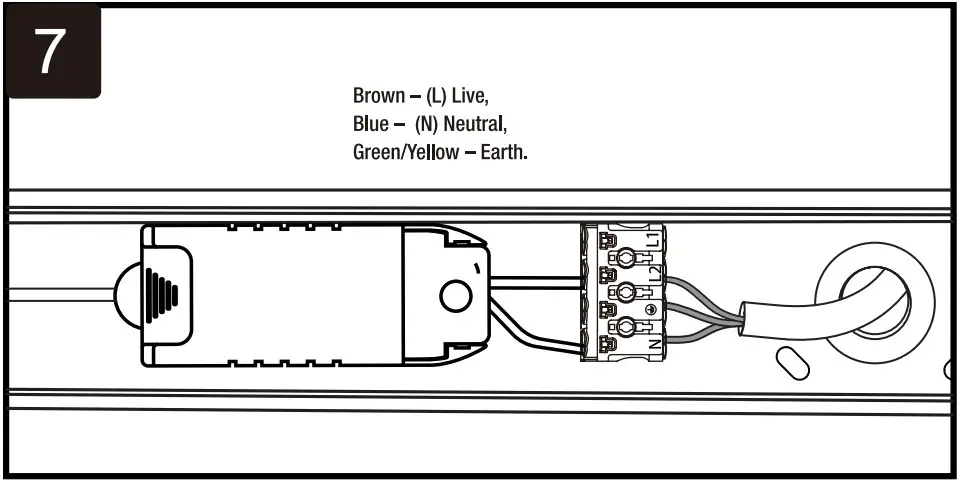
- Connect supply leads with terminal brown (L) to brown, blue (N) to blue & greenish-yellow ( ) to greenish-yellow.
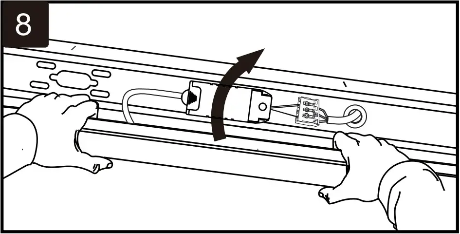
- Gently push fit the front cover/diffuser to the backside fitting until you hear a click sound. Ensure the fitting is properly fixed.
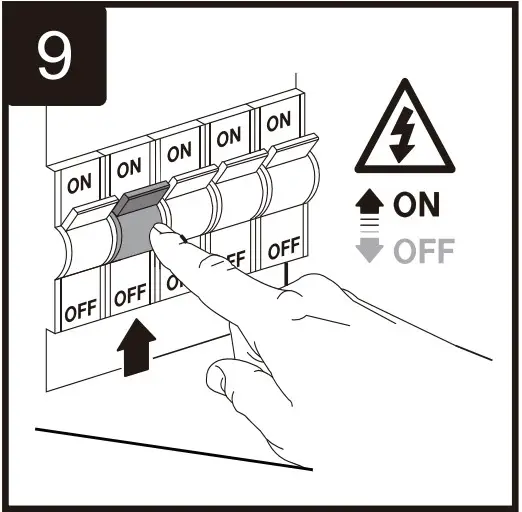
- Switch ON the power to test the light.
WIRING DIAGRAM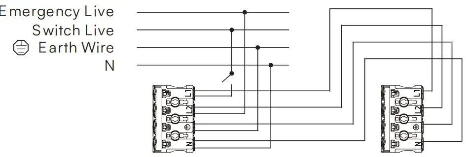
EMERGENCY WIRING DIAGRAM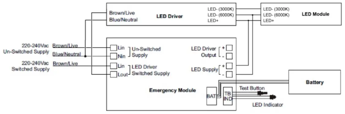
NOTE:
- Before installation, to connect the battery.
- After installation, allow 24 hours to ensure full battery charge and then interrupt the supply.
CAUTION:
To ensure its performance, battery pack should be charged for 24 hours every 6 months\ during storage.
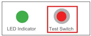
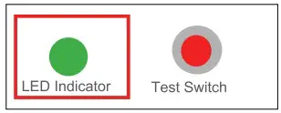
TEST SWITCH AND LED INDICATOR:
The Test Switch and LED indicator on the luminaire provide an indication of the status of the luminaire during testing and normal operation
| Test Switch s LED indictor | ON | OFF |
 |
|
|
 |
|
|
LINKABLE UNITS WIRING DIAGRAM
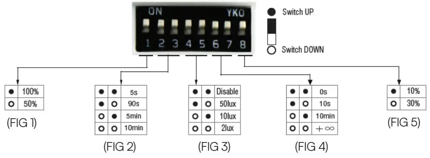
Detection Area – It can be adjusted by combining DIP switches for specific application [FIG 1].
Hold Time – Time period during which the light will be ON after the last detection [FIG 2].
Daylight Threshold – Daylight sensor priors motion sensor. Set Threshold for Specific needs. If disabled, only motion sensor will work [FIG 3].
Stand-by Period – This is the time period during which the light keeps dimming down after the last detection [FIG 4].
Stand-by dimming level – The dimming level during which the light is ON during the stand-by Period [FIG 5].
AUTOMATICALLY ON/OFF FUNCTION
With sufficient daylight, even when motion detected, light remains OFF.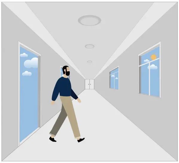
With insufficient daylight, the sensor turns light ON when motion gets detected.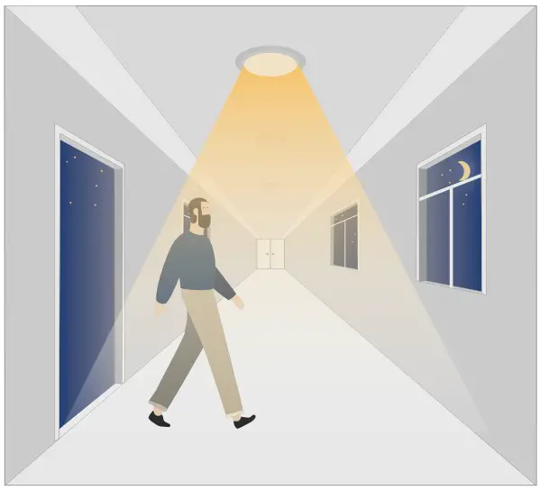
The sensor turns OFF light automatically after the holdtime when there’s no motion detected.
DAYLIGHT DISABLE
The sensor turns light ON when motion gets detected.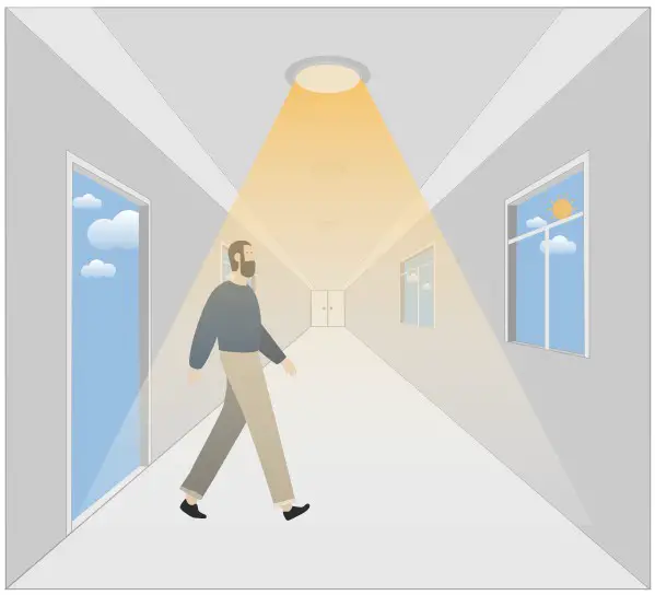
The sensor keeps light ON for holdtime period after motion leaves.
The sensor turns OFF light automatically after the holdtime.
When daylight threshold is preset as “disable”, the sensor turns light ON when motion gets detected, and OFF after holdtime.
CORRIDOR FUNCTION, BI-LEVEL DIMMABLE
With sufficient daylight, the sensor keeps light OFF even motion gets detected.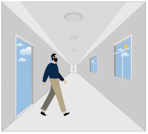
With insufficient daylight, the sensor turns light ON when motion getsdetected.
After there’s no motion detected, the sensor keeps light ON 100% for holdtime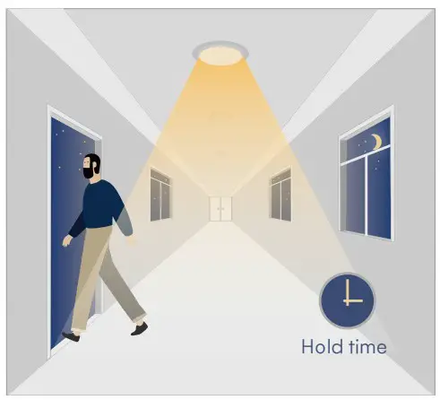
After holdtime, sensor dims light to standby dimming level for standby period.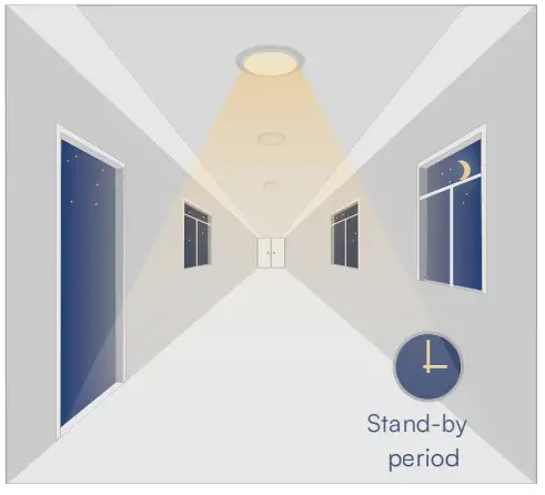
The sensor turns OFF light automatically after the standby period when there’s no motion detecte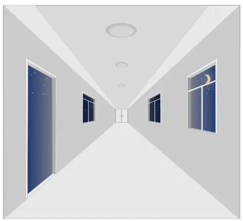
REMOTE CONTROL (PURCHASE SEPERATELY)