![]() INSTALLATION GUIDE
INSTALLATION GUIDE
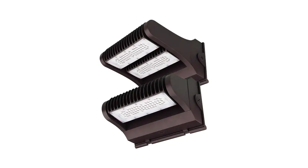
FWPR/2 Series LED WALL MOUNT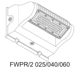
IMPORTANT
READ CAREFULLY BEFORE INSTALLING THE FIXTURE. RETAIN THESE INSTRUCTIONS FOR FUTURE REFERENCE.
PacLights fi fixtures must be wired in accordance with the National Electrical Code and all applicable local codes. Proper grounding is required for safety.
THIS PRODUCT MUST BE INSTALLED IN ACCORDANCE WITH THE APPLICABLE INSTALLATION CODE BY A PERSON FAMILIAR WITH THE CONSTRUCTION AND OPERATION OF THE PRODUCT AND THE HAZARDS INVOLVED.
WARNINGS:
• Make certain power is OFF before installing or maintaining the fixture. No user-serviceable parts inside.
• To prevent wiring damage or abrasion, do not expose wiring to edges of sharp objects.
CAUTION:
• For proper weatherproof function all gaskets must be seated properly and all screws inserted and tightened firmly. Apply weatherproof silicone sealant around the edge of the BackBox and/or Junction Box. This is especially important with an uneven wall surface. Silicone all plugs and unused conduit entries.
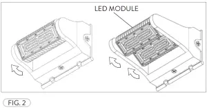
ROTATABLE LIGHTING MODULES
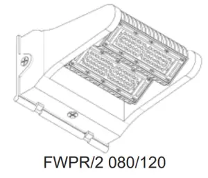
All FWPR/2 fixtures have LED Modules that can be rotated, from facing the ground to facing away from the wall at an angle. Loosen the Set Screw(s), located at the side of each Module, then rotate the Module(s) to the desired angle and tighten the Set Screw(s) (Fig. 1). The FWPR/2 fixtures below show the Module rotations (Fig. 2).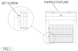
 WIRING DIAGRAM
Connect the ACL and the ACN from the FWPR/2 Fixture to the conduit with the AC Power Supply Cable. Follow the Wiring Diagram provided.
AC POWER SUPPLY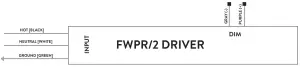
FWPR/2 PHOTOCELL CONTROL (OPTIONAL)
The Optional Photocell Control allows on/off switching the fixtures based on the amount of daylight present. Prior to installing, loosen the Screws (2) that hold the FWPR/2 Back Cover and then open. Remove the Cap Screw at the side/top (Location based on photocell used) of the Back Cover for the Photocell Control (Fig. 3).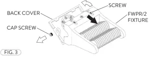
Insert the Photocell Control through the threaded hole at the side/top of the FWPR/2 Back Cover. Fasten the Nut to secure the Photocell Control to the fixture. Fasten the Lens Cover for protection (Fig. 4). Apply sealant to connection for a water-tight seal (Not included). 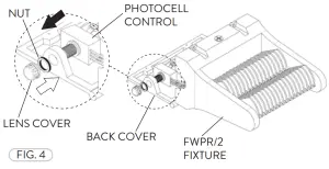
Attach the Photocell Control Wires to the Driver and Power Supply(Fig. 5). Refer to Photocell Control Wiring Diagram.
PHOTOCELL CONTROL WIRING DIAGRAM
The LED Driver input cable consists of 3 conductors: ACL (black), ACN (white), and ground (green). These conductors are to be connected to a 100-277v Power Supply Cable.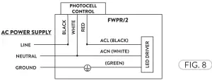
FWPR/2 JUNCTION BOX INSTALLATION
Prior to Junction Box installation, loosen the Screws (2) that hold the FWPR/2 Back Cover giving access to the fixture wiring (Refer to Fig. 3). The Back Cover of the FWPR has a raised drill pattern on the inside that can be drilled through for the Junction Box. Align the desired Junction Box (not included) and drill holes to align with the Junction
Box of your choosing (Fig. 6).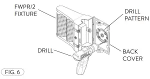
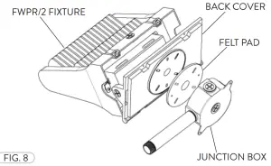
Remove the Cap Screw from the Back Cover of the FWPR/2 fixture (Fig. 7).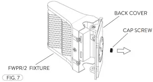 Place the Felt Pad (with pre-cut hole patterns) between the Junction Box and Back Cover. Fasten the Junction Box to the Back Cover of the FWPR/2 fixture (Fig. 8). Apply sealant where necessary (Not included). Refer to the wiring diagram.
Need help? (800) 988 -6386 Email: [email protected] Website: www.PacLights.com
Instructions and specifi cations are subject to change at any time without notice. Copyright© 2021 PacLights All Rights Reserved


