
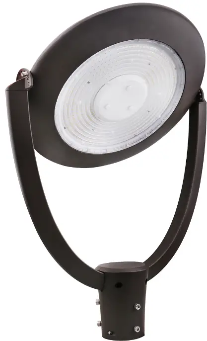
 PacLights FPTA generation 2 Series LED POST TOP LIGHT
  INSTALLATION GUIDE
 INSTALLATION GUIDE
IMPORTANT
READ CAREFULLY BEFORE INSTALLING FIXTURE. RETAIN THESE INSTRUCTIONS FOR FUTURE REFERENCE.
PacLights fi xtures must be wired in accordance with the National Electrical Code and all applicable local codes. Proper grounding is required for safety. THIS PRODUCT MUST BE INSTALLED IN ACCORDANCE WITH THE APPLICABLE INSTALLATION CODE BY A PERSON FAMILIAR WITH THE CONSTRUCTION AND OPERATION OF THE PRODUCT AND THE HAZARDS INVOLVED.
WARNINGS:
- Make certain power is OFF before installing or maintaining fi fixture. No user-serviceable parts inside.
- To prevent wiring damage or abrasion, do not expose wiring to the edges of sharp objects.
CAUTION: - For proper weatherproof function, all gaskets must be seated properly and all screws inserted and tightened firmly. Apply weatherproof silicone sealant around the edge of the Back Box and/or Junction Box. This is especially important with an uneven wall surface. Silicone all plugs and unused conduit entries.
FPTA/2 LIGHT MODULE ANGLE ADJUSTABLE
The FPTA/2 fixture removed from the box is in a vertical confi duration (Fig. 1). The FPTA/2 fixture can be rotated in various angles up to ±90°. Remove the Screws from each side and rotate the Light Module of the FPTA/2 fixture to the desired angle (Fig. 2). Fasten the Screws to secure the Light Module in place (Fig. 3).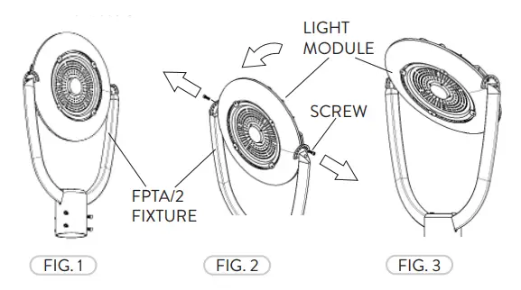
OPTIONAL PHOTOCONTROL
The Photocontrol has a Dusk to Dawn functionality.
Note: If the Photocontrol is not included the following can be skipped. If the Photocontrol is included prior to fi eld installation, the following can be skipped.
All FPTA/2 fixtures come with a NEMA Three-Prong Twist Lock receptacle with a Short-Cap pre-installed. Remove the Short-Cap by twisting CCW and lifting (Fig. 4). Place the Photocontrol on the NEMA receptacle. Carefully push down and twist CW (Fig. 5). 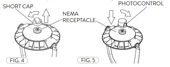
WIRING DIAGRAM
Connect the ACL and the ACN from the FPTA/2 fixture to the conduit with the AC power Supply Cable. Follow the Wiring Diagram provided.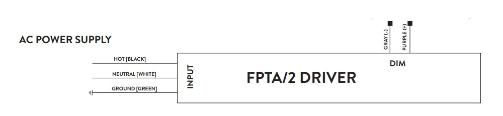
OPTIONAL BI-LEVEL MOTION CONTROL
The integrated Bi-Level Motion Control is a programmable microwave motion detector.
Note: If the Bi-Level Motion Control is not included or adjustment is not needed, the following steps can be skipped.
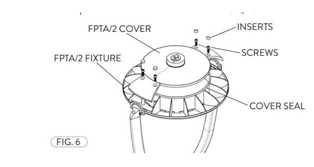
- Remove the flush rubber inserts from the Cover. Remove the Screws from the Cover. Lift the Cover from the FPTA fi xture. The fi xture is now open to adjust (if needed) the Bi-Level Motion Control setting. The process is the same for all FPTA Fixtures (Fig. 6).

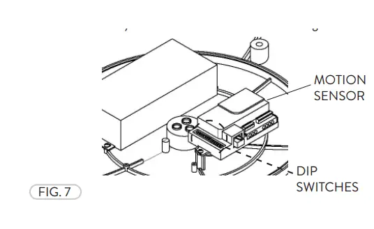
- The default settings can be changed by adjusting the DIP Switches on the Bi-Level Motion Control. Please refer to the table on this page and also directly on the Bi-Level Motion Control (Fig. 7).

BI-LEVEL MOTION CONTROL DIP PIN SETTING
Selecting the combination on the DIP switches, sensor data can be precisely set for each specifi c application as seen below.
- Detection Area
A detection area having motion and not enough ambient light will activate the sensor. The sensor can be set at 100%, 75%, 50%, or 25%.ON
1 2 I ON ON 100% II ON – 75% III – ON 50% IV – – 25% - Hold Time
Hold Time refers to the time period the fi xture remains at 100% illumination after no motion is detected. Hold Time can range from 5s to 20 minutes. The fi xture will remain at full illumination until ‘Hold Time’ ends, then reducing to Stand-By Dimming Level.
Factory setting = VION
3 4 5 I ON ON ON 5S II – ON ON 30S III ON – ON 90S IV – – ON 3min V ON ON – 20min VI – – – +∞ - Stand-By Period
The Stand-By period begins when the ‘Hold Time’ ends. The fixture remains at a Stand-By Dimming Level before it completely switches off while motion is not present. When set ‘+∞’ mode, the low led light is held until motion is detected.
Factory setting = ION
6 7 8 I ON ON ON 0S II – ON ON 5S III ON – ON 5min IV – – ON 10min V ON ON – 30min VI – ON – 1h VII – – – +∞ - Stand-By Dimming Level
Stand-By Dimming Level is when ‘Hold Time’ has ended, there is no movement in the area and the light output is reduced.
Factory setting = ION
1 2 I ON ON 50% II – ON 30% III ON – 20% IV – – 10% - Daylight Sensor
The Daylight Sensor measured in LUX can be set to allow the fixture to illuminate below a surrounding minimum brightness threshold. The sensor can be set from 5 to 150 LUX. When set to Disable mode, the Daylight Sensor will switch ‘ON’ the fixture when motion is detected regardless of ambient light. Factory setting = VIION
3 4 5 6 I ON ON ON ON 5Lux II – ON ON ON 15Lux III ON – ON ON 30Lux IV – – ON ON 50Lux V ON ON – ON 100Lux VI ON ON ON – 150Lux VII – – – – Disable


