Paclights FFLA Generation 2 Series FFLA-2 LED Flood Light
IMPORTANT
READ CAREFULLY BEFORE INSTALLING FIXTURE. RETAIN THESE INSTRUCTIONS FOR FUTURE REFERENCE. PacLights fixtures must be wired in accordance with the National Electrical Code and all applicable local codes. Proper grounding is required for safety. THIS PRODUCT MUST BE INSTALLED IN ACCORDANCE WITH THE APPLICABLE INSTALLATION CODE BY A PERSON FAMILIAR WITH THE CONSTRUCTION AND OPERATION OF THE PRODUCT AND THE HAZARDS INVOLVED.
WARNINGS:
- Make certain power is OFF before installing or maintaining fixture. No user serviceable parts inside.
- To prevent wiring damage or abrasion, do not expose wiring to edges of sharp objects.
CAUTION:
- For proper weatherproof function all gaskets must be seated properly and all screws inserted and tightened firmly. Apply weatherproof silicone sealant around the edge of the Back Box and/or Junction Box. This is especially important with an uneven wall surface. Silicone all plugs and unused conduit entries.
FFLA/2 3CCT (Color Coordinated Temperature) & LUMEN FIELD SELECTABLE WITH PHOTO CONTROL
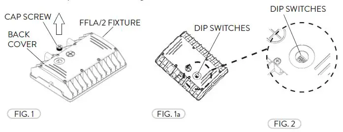
- The Selectable CCT & Lumen output is equipped on selected models. If the CCT or Lumen output needs to be adjusted or if the Photo Control turned on/off , remove the clear plastic Cap Screw from the back of the FFLA/2 fixture (Fig. 1). The Dip Switches can be accessed easliy inside the fixture (Fig. 1a).

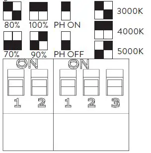
- There is a Dip Switch Chart to follow next to the Dip Switches inside. The first set of Switches controls the Lumen output. The second set controls the Photo Control ON/OFF and the Color Temperature (Fig. 2). After the selection is made replace the clear plastic Cap Screw and carefully tighten.

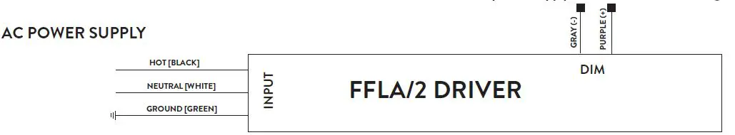
WIRING DIAGRAM
Connect the ACL and the ACN from the FFLA/2 Fixture to the conduit with the AC power Supply Cable. Follow the Wiring Diagram provided.
INSTALLATION GUIDE
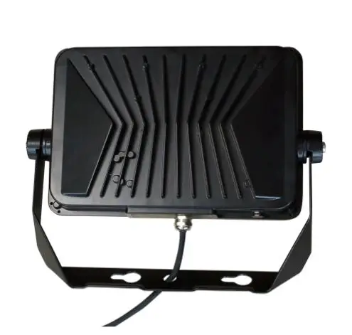
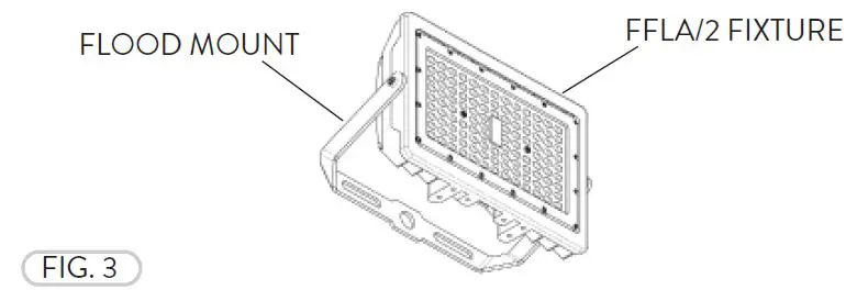
FFLA/2 FLOOD MOUNT
- The Flood Mount available for all FFLA/2 fixtures (Fig. 3).

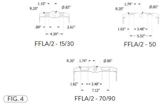
- The FFLA/2 Flood Mount drilling patterns (Fig. 4).

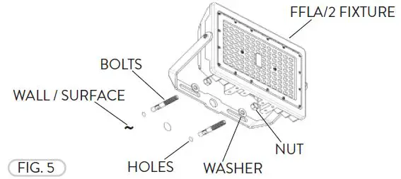
- The Flood Mount can be mounted to a Wall/Surface. Align the Flood Mount to the holes pre-drilled on the mounting surface and bolt the fixture to the wall (appropriate mounting Bolts, Washers, and Nuts not included) (Fig. 5).

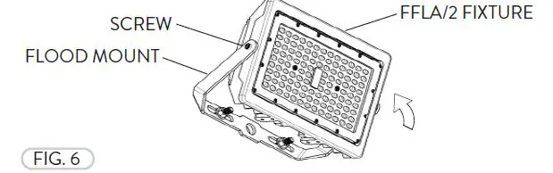
- The Flood Mount can be rotated. Loosen the Cap Head Screws (2) and adjust the tilt angle of the FFLA/2 fixture to point towards the desired location. Tighten the Screws to hold the FFLA/2 fixture in place (Fig. 6).

FFLA/2 KNUCKLE MOUNT
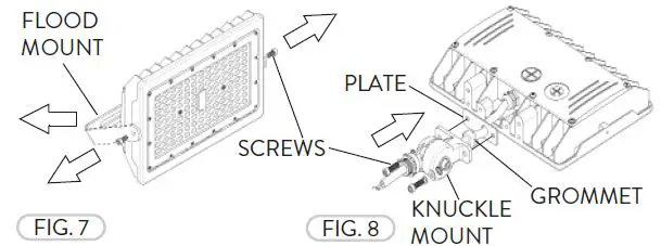
- The Knuckle Mount is available for all FFLA/2 fixtures. If installed, remove the Flood Mount by removing the Screws (Fig. 7). Install the Knuckle Mount, Plate, and rubber Wire Grommet by aligning to the holes (2) at the base of the FFLA/2 fixture. Fasten them with the Cap Head Screws and Washers provided (Fig. 8).

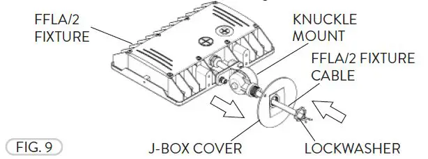
- The FFLA/2 Knuckle Mount can be mounted directly to a Junction Box. Install the fixture to a J-Box Cover with a conduit threaded opening. Fasten the J-Box Cover and lock in place with the Lockwasher included with the FFLA/2 (Fig. 9).

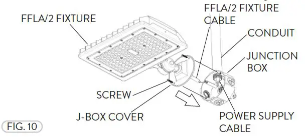
- Follow the Wiring Diagram and properly wire the FFLA/2 fixture to the Power Supply Cable from the Conduit. Fasten the Junction Box Cover to the Junction Box with the Screws (not included) (Fig. 10).

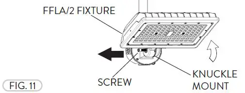
- Loosen the Socket Head Screw on the Knuckle Mount and pull apart to separate the teeth and adjust the tilt angle to the desired position. Once adjusted, align the teeth and fasten the Screw to lock the Knuckle Mount and FFLA/2 fixture in place (Fig. 11).

FFLA/2 YOKE MOUNT
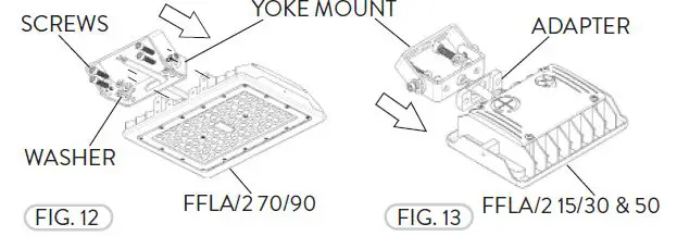
- The Yoke Mount is available for all FFLA/2 fixtures. If installed, remove the Flood Mount by removing the the Cap Head Screws (Refer to Fig. 7). Install the Yoke Mount, Cap Head Screws and Washers by aligning to the holes (4) at the base of the FFLA/2 70/90 fixture (Fig. 12). The FFLA/2 15/30 & 50 fixtures have an Adapter Spacer for the fixture Cable that fits between the fixture and the Yoke Mount (Fig. 13). Fasten with the Cap Head Screws and Washers provided.

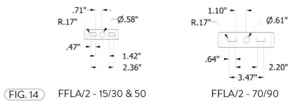
- The FFLA/2 Yoke Mount drilling patterns (Fig. 14).

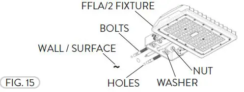
- The Yoke Mount can be mounted to a Wall/Surface. Align the Yoke Mount to the holes pre-drilled on the mounting surface and bolt the fixture to the wall (appropriate mounting Bolts, Washers, and Nuts not included) (Fig. 15).

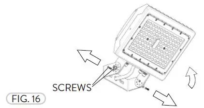
- The Yoke Mount can be rotated. Loosen the center Cap Head Screws (2) and remove the smaller Cap Head Screws to adjust the tilt angle of the FFLA/2 fixture to point towards the desired location. Replace the smaller Cap Head Screws and tighten all of the Cap Head Screws to hold the fixture in place (Fig. 16).

FFLA/2 SLIPFITTER MOUNT
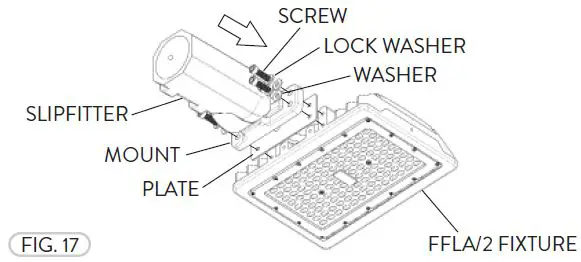
- The Slipfitter Mount is only available for FFLA/2 70/90 fixtures. If installed, remove the Flood Mount by removing the the Cap Head Screws (Refer to Fig. 7). Install the FFLA/2 Slipfi tter Mount with Mount, Plate, Screws, Washers, and Lock Washers (Fig. 17).

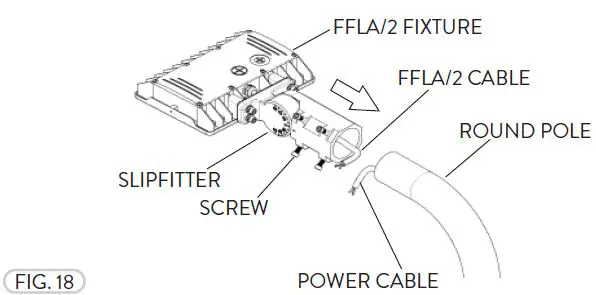
- The Slipfitter Mount can be mounted on a Round Pole (Fig. 18). Run the FFLA/2 Cable from the FFLA/2 fixture and the Slipfi tter Mount to the Pole and follow the Wiring Diagram provided to properly install the light fi xture to the Power Supply Cable. All wiring must be installed by a certified electrician and must be compliant to NEC standards. Tighten the Slipfitter Screws (4) to secure the FFLA/2 fi xture to the Round Pole.

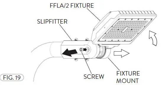
- If needed to tilt the FFLA/2 fixture, loosen the Socket Head Screw to unmate the teeth of the Fixture Mount and the Slipfi tter and rotate (Fig. 19).

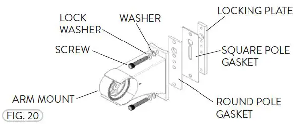
FFLA/2 ARM MOUNT
- The Arm Mount is only available for FFLA/2 70/90 fixtures (Fig. 20). The Arm Mount can be mounted on either a Square or Round pole.

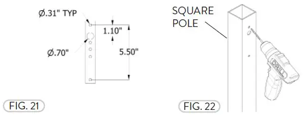
- The Arm Mount drilling template is for either a Square or Round pole (Fig. 21). Drill holes on the Square pole by following the Drilling Template to mount the FFLA/2 to the desired height (Fig. 22).

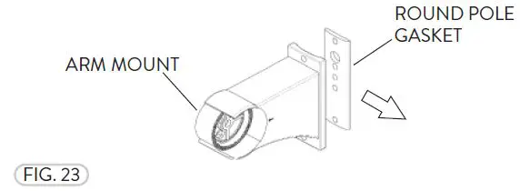
- If the FFLA/2 fixture is being installed to a Square Pole, remove the Round Pole Gasket (Fig. 23).

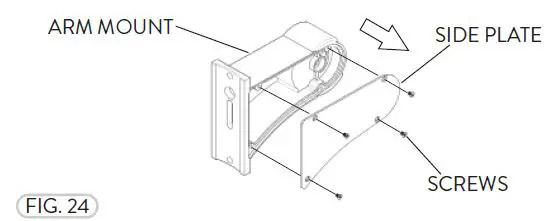
- Remove the Screws (4) and the Side Plate from the Arm Mount before installing the FFLA/2 fixture (Fig 24).

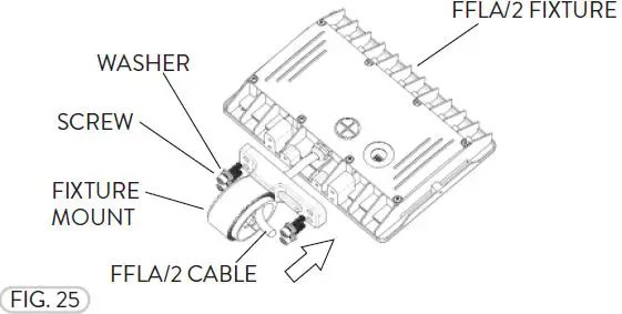
- Place the Fixture Mount on the FFLA/2 fixture and fasten them together with the Screws and Washers (Fig. 25).

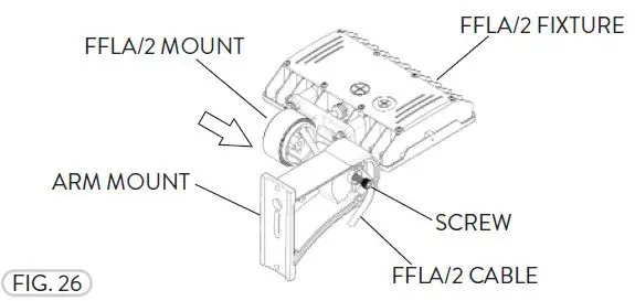
- Run the FFLA/2 Cable through the inside the Arm Mount. Align the hole and teeth from the Arm Mount with the FFLA/2 Mount and use the Cap Head Screw to fasten them together at the desired fixture tilt angle (Fig. 26).

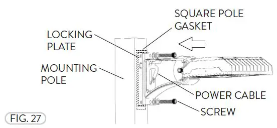
- Run the Power Cable through the Pole. Place the Locking Plate and Gasket inside the Mounting Pole and fasten the FFLA/2 fixture with the Arm Mount onto the Pole with the Cap Head Screws (Fig. 27). For the Round Pole, repeat Steps 2-6, except the remove the Square Pole Gasket for Step 2. Reinstall the Side Plate (Fig. 24).

Need help? (800) 988 -6386
Email: [email protected]
Website: www.PacLights.com
Instructions and specifications are subject to change at any time without notice. Copyright© 2021 PacLights All Rights Reserved


