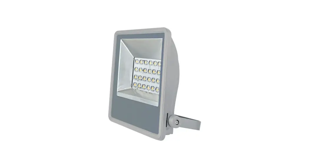
![]() Opus 3 LED Flood Light
Opus 3 LED Flood Light
Installation Guide
Opus 3 LED Flood Light
220-240V / 50-60Hz IP65![]()
Terminal Labelling:
Power
| L1 | Switched Live |
| E | Earth |
| N | Neutral |
Emergency
| L2 | Unswitched Live |
| DA/AT3 | DALI Autotest |
| DA/AT3 | DALI Autotest |
Dimming
| -/D1/DA | Analogue/DSI/DALI |
| +/D2/DA | Analogue/DSI/DALI |
| L3 | Switch Dim / Corridor Function |
WARNING: Luminaire must be earthed. Risk of electric shock from LED boards if operated with cover removed. Installation / operation outside of luminaires intended scope invalidates warranty. Suitable only for domestic / light industrial / industrial applications within the scope of EN55015.
Tested to compliance with BSEN 60598: specification for general requirements and tests. Must be installed by a suitably qualified person in accordance with all relevant legislation. Ambient operating temperature of 0°C to 25°C. If maximum operating temperature is exceeded luminaire will automatically dim / switch off. Terminal blocks are rated to 16A unless stated otherwise. The light source is non replaceable.
LUMINAIRES WITH EMERGENCY PACK:
When supply is isolated battery output terminals may be live if battery is connected. Isolate mains and battery before servicing. Emergency luminaires require Unswitched live connection taken from same phase as switched supply. When Unswitched supply is connected status indicator illuminates green, when Unswitched supply is disconnected indicator extinguishes and luminaire operates in emergency mode. 24 hour charge period required before undertaking full discharge test. Emergency test sheets provided should be used to record all emergency tests. Batteries should be replaced when 3 hour duration is not met. Excessive switching of permanent live may result in premature battery failure. Battery electrolyte can be harmful to eyes / open wounds, do not puncture, if electrolyte touches skin / eyes flush with water. Do not incinerate batteries.
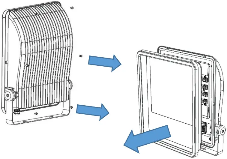
- Remove screws securing the frame and retain.
Carefully remove the frame and glass and store safely.
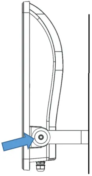
- Secure saddle bracket to a suitable surface making sure that all limitations have been observed.
To adjust the angle of the saddle bracket, use an Allen key to loosen the Hex bolts in the sides. Retighten once at desired angle.
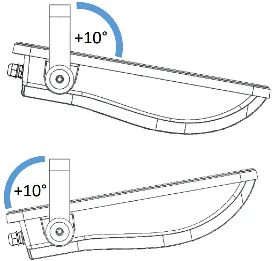
- If mounting in an orientation shown, ensure fitting is angled by 10° to prevent water pooling on the front cover

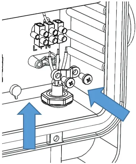
- Feed mains cable into body and wire into respective terminals. Ensure the cable clamp bar is used to secure the cable.

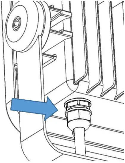
- Ensure the cable gland is fully tightened. Under tightening may result in failure of IP65 rating.

- Reverse step 1 to replace frame and glass.
Do not exceed 1.5NM torque when securing front frame screws.
DIL-0269-0001
Revision – E![]()


