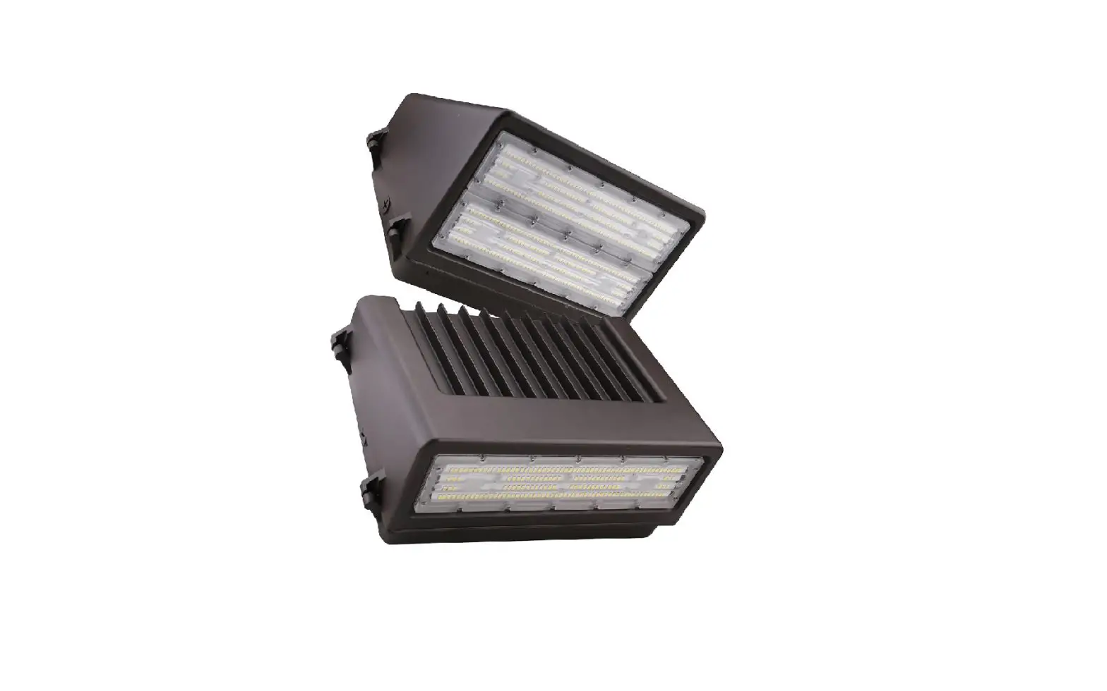

PacLights FWPC Series LED WALL MOUNT
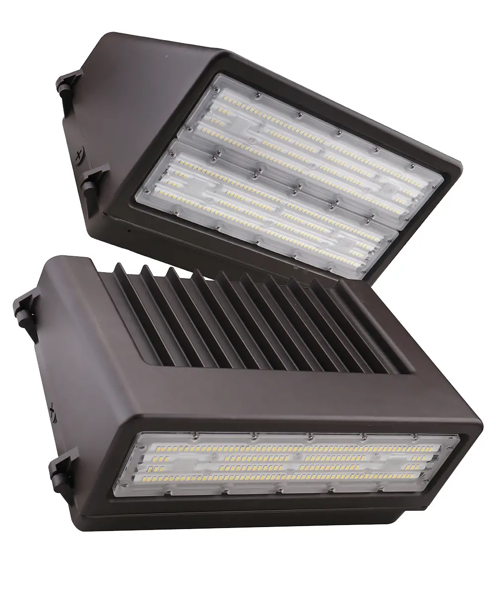
Models
FWPC 040/060/080
FWPC 100/120/150
IMPORTANT Instructions
READ CAREFULLY BEFORE INSTALLING FIXTURE. RETAIN THESE INSTRUCTIONS FOR FUTURE REFERENCE.
PacLights fi xtures must be wired in accordance with the National Electrical Code and all applicable local codes. Proper grounding is required for safety. THIS PRODUCT MUST BE INSTALLED IN ACCORDANCE WITH THE APPLICABLE INSTALLATION CODE BY A PERSON FAMILIAR WITH THE CONSTRUCTION AND OPERATION OF THE PRODUCT AND THE HAZARDS INVOLVED.
WARNINGS:
- Make certain power is OFF before installing or maintaining fi xture. No user serviceable parts inside.
- To prevent wiring damage or abrasion, do not expose wiring to edges of sharp objects.
CAUTION: - For proper weatherproof function all gaskets must be seated properly and all screws inserted and tightened fi rmly. Apply weatherproof silicone sealant around the edge of the Back Box and/or Junction Box. This is especially important with an uneven wall surface. Silicone all plugs and unused conduit entries.
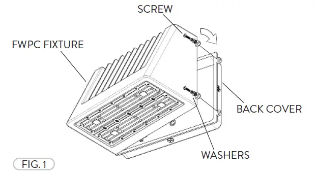
- The Selectable CCT is equipped on selected models. If the CCT needs to be adjusted, loosen the Screws (2) at the side of the FWPC fi xture and open the Back Cover. The Screws and Washers do not have to be removed (Fig. 1).

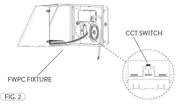
- The Selectable CCT Switch is a device that allows the user to choose a desired color temperature 3000K, 4000K, 5000K (Fig. 2). After the selection is made close the Back Cover and tighten the Screws.

WIRING DIAGRAM
Connect the ACL and the ACN from the FWPC Fixture to the conduit with the AC power Supply Cable. Follow the Wiring Diagram provided.
FWPC PHOTOCELL CONTROL (OPTIONAL)
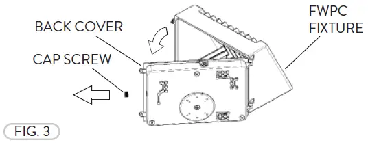
- The Optional Photocell Control allows on/off switching the fi xtures based on the amount of daylight present. Prior to installing, loosen the Screws at the side of the fi xture and open the Back Cover (Refer to Fig. 1). Remove the Cap Screw at the side/top (Location based on photocell used) of the Back Cover for the Photocell Control (Fig. 3).

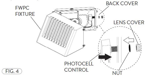
- Insert the Photocell Control through the threaded hole at the side/top of the FWPC fi xture Back Cover. Fasten the Nut to secure the Photocell Control to the fi xture. Fasten the Lens Cover for protection (Fig. 4). Apply sealant to connection for a water tight seal (Not included).

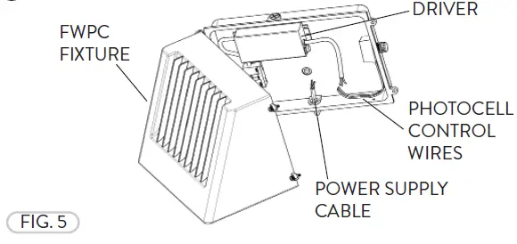
- Attach the Photocell Control Wires to the Driver and Power Supply. (Fig. 5). Refer to Photocell Control Wiring Diagram.

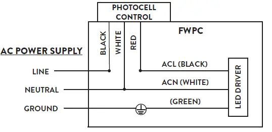
PHOTOCELL CONTROL WIRING DIAGRAM
The LED Driver input cable consists of 3 conductors: ACL (black), ACN (white), and ground (green). These conductors are to be connected to a 100-277v Power Supply Cable.
FWPC JUNCTION BOX INSTALLATION
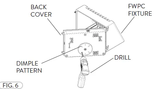
- Prior to Junction Box installation, loosen the Screws (2) on the side of the FWPC fi xture to open the Back Cover to have access to the fi xture Wiring (Refer to Fig. 1). The Back Cover of the FWPC has indented dimple pattern that can be drilled through for the Junction Box. Align the desired Junction Box (not included) and drill holes to align with the Junction Box of your choosing (Fig. 6).

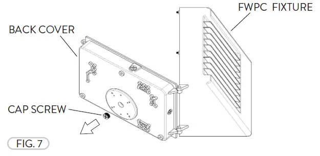
- Remove the Cap Screw from the Back Cover of the FWPC fixture (Fig. 7).

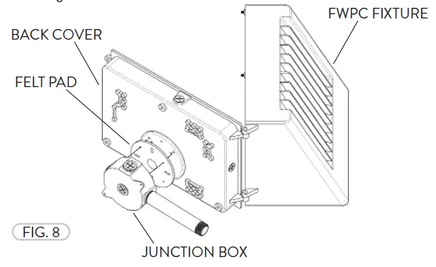
- Place the Felt Pad between the Junction Box and Back Cover. Fasten the Junction Box to the Back Cover of the FWPT fi xture (Fig. 8). Apply sealant where necessary (Not included). Refer to wiring diagram.

Need help? (800) 988 -6386 Email: [email protected] Website: www.PacLights.com Instructions and specifi cations are subject to change at any time without notice. Copyright© 2021 PacLights All Rights Reserved


