![]() Home
Home![]()
THP2400A1027
Cover Plate Assembly
INSTALLATION INSTRUCTIONS
APPLICATION
Use the THP2400A1027 cover plate assembly with the Prestige
IAQ thermostat.
- THP2400A1027W – White
- THP2400A1027G – Gray
- THP2400A1027B – Black
Use the THP2400A1027 cover plate assembly to cover marks on the wall or to mount the thermostat to a 2 in. x 4 in. electrical box.
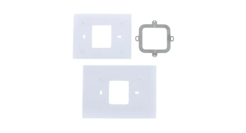
The THP2400A1027 cover plate assembly contains two cover plates (small and large), one bracket, two #6-32 x 5/8 flat head screws, and two #6-32 x 1/4 pan heads screws. See Fig. 1.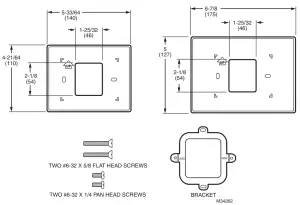
Fig. 1. THP2400A1027 cover plate assembly.
THP2400A1027 COVER PLATE ASSEMBLY
INSTALLATION
When Installing this Product…
- Read these instructions carefully. Failure to follow them could damage the product or cause a hazardous condition.
- Check ratings given in the instructions and on the product to make sure the product is suitable for your application.
- The installer must be a trained, experienced service technician.
- After installation is complete, check out product operation as provided in these instructions.
CAUTION
Electrical Hazard.
Can cause electrical shock or equipment damage.
Disconnect power before beginning installation.
Mount Cover Plate
Mount Cover Plate Directly to Wall (See Fig. 2)
- Pull the wires through the wire hole on the cover plate and wall plate.
- Position the cover plate and wall plate on the wall with the arrows pointing up. Level the wall plate for appearance only.
- Use a pencil to mark the mounting holes for your thermostat.
- Remove the cover plate and wall plate from the wall. Drill anchor holes. If your thermostat box contains red anchors, drill 7/32” holes. If your box contains yellow anchors, drill 3/16” holes. Tap the wall anchors (provided with the thermostat) into the holes, until the anchor collar touches the wall.
- Pull the wires through the wire hole on the cover plate and wall plate. Position the cover plate and wall plate on the wall anchors.
- Insert the mounting screws (provided with the thermostat: #8 1-1/2″ for red anchors and #6 1-1/2″ for yellow anchors) into the wall anchors. Check to level, if desired, and tighten the mounting screws.
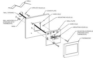
Fig. 2. Mount cover plate, wall plate, and thermostat directly to the wall.
Mount Cover Plate to a Vertical 2 in. X 4 in. Electrical Box (See Fig. 3)
- Position the bracket on the electrical box. Insert two #6-32 X 5/8 flat head screws. Check to level, if desired, and tighten the flat head screws.
- Pull the wires through the wire hole on the cover plate and wall plate. Position the cover plate and wall plate on the bracket with the arrows pointing up.
- Insert two #6-32 X 1/4 pan head screws and tighten.
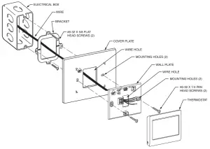
Fig. 3. Mount bracket, cover plate, wall plate, and thermostat to a vertical 2 in. X 4 in. electrical box.
Mount Cover Plate to a Horizontal 2 in. X 4 in. Electrical Box (See Fig. 4)
- Pull the wires through the wire hole on the cover plate and wall plate. Position the cover plate and wall plate on the electrical box with the arrows pointing up.
- Insert two #6-32 X 5/8 flat head screws. Check to level, if desired, and tighten the flat head screws.
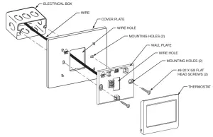 Fig. 4. Mount cover plate, wall plate, and thermostat to a horizontal 2 in. X 4 in. electrical box.
Resideo Inc., 1985 Douglas Drive North,
Golden Valley, MN 55422
69-2759EFS—03 M.S. Rev. 12-19
Printed in the United States
This product is manufactured by Resideo Technologies, Inc., Golden Valley, MN, 1-800-468-1502
©2019 Resideo Technologies, Inc. The Honeywell Home trademark is used under license from Honeywell International Inc. All rights reserved.


