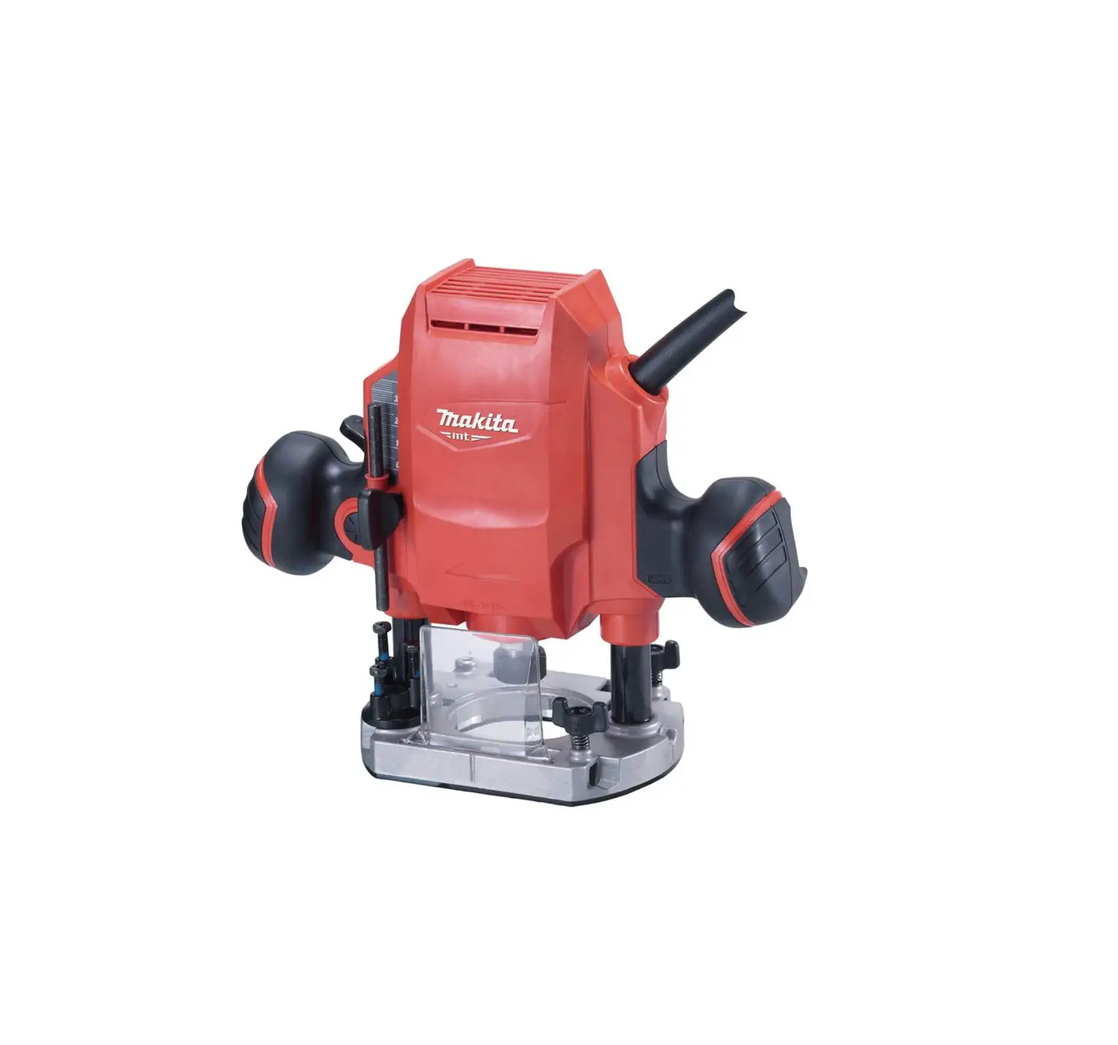
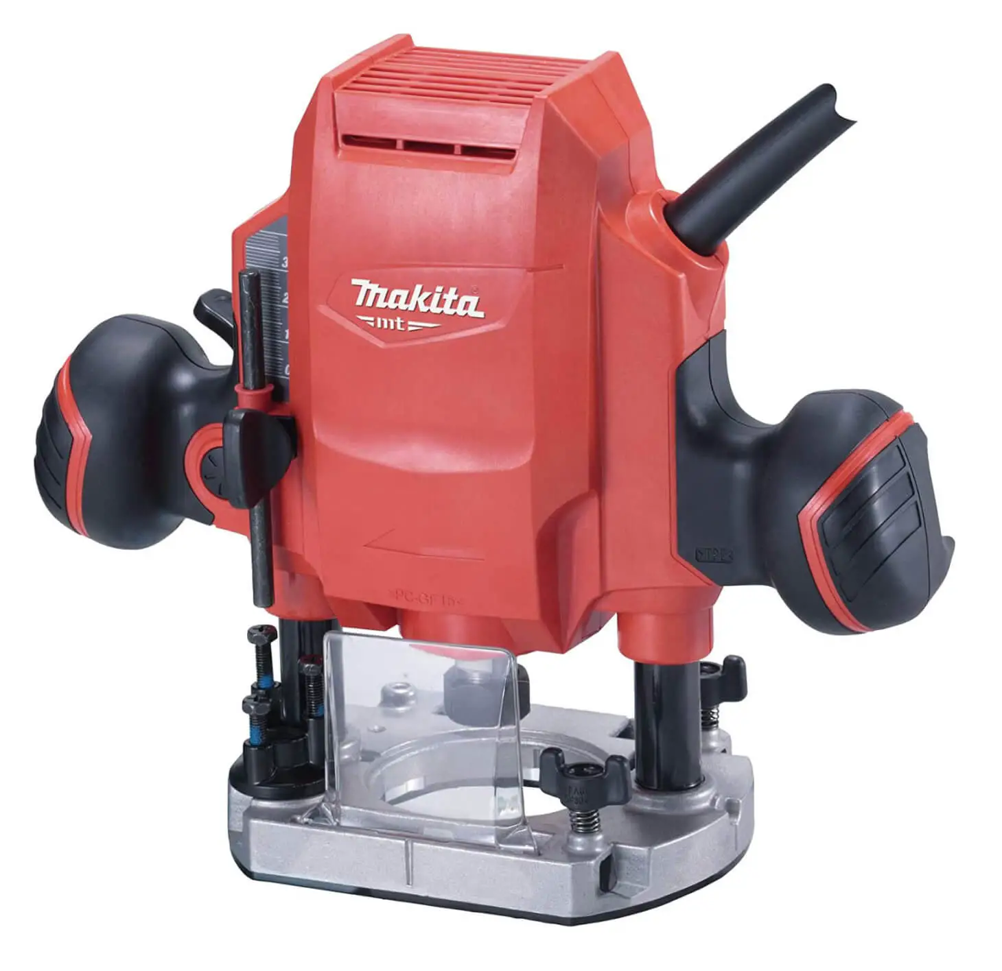
makita M3601 Electric Router
SPECIFICATIONS
| Model: | M3601 |
| Collet chuck capacity | 6 mm, 1/4″ and/or 8 mm |
| Plunge capacity | 0 – 35 mm |
| No load speed | 27,000 min-1 |
| Overall height | 218 mm |
| Net weight | 2.7 kg |
| Safety class | /II |
- Due to our continuing program of research and development, the specifications herein are subject to change without notice.
- Specifications may differ from country to country.
- Weight according to EPTA-Procedure 01/2014
Intended use
The tool is intended for flush trimming and profiling of wood, plastic and similar materials.
Power supply
The tool should be connected only to a power supply of the same voltage as indicated on the nameplate, and can only be operated on single-phase AC supply. They are double-insulated and can, therefore, also be used from sockets without earth wire.
Noise
The typical A-weighted noise level determined according to EN62841-2-17:
Sound pressure level (LpA) : 89 dB(A)
Sound power level (LWA) : 100 dB (A)
Uncertainty (K) : 3 dB(A)
| NOTE: The declared noise emission value(s) has been measured in accordance with a standard test method and may be used for comparing one tool with another. NOTE: The declared noise emission value(s) may also be used in a preliminary assessment of exposure. |
Vibration
The vibration total value (tri-axial vector sum) determined according to EN62841-2-17:
Work mode: cutting grooves in MDF
Vibration emission (ah): 7.9 m/s2
Uncertainty (K): 1.6 m/s2
| NOTE: The declared vibration total value(s) has been measured in accordance with a standard test method and may be used for comparing one tool with another. NOTE: The declared vibration total value(s) may also be used in a preliminary assessment of exposure. |
| WARNING: The vibration emission during actual use of the power tool can differ from the declared value(s) depending on the ways in which the tool is used especially what kind of workpiece is processed. WARNING: Be sure to identify safety measures to protect the operator that are based on an estimation of exposure in the actual conditions of use (taking account of all parts of the operating cycle such as the times when the tool is switched off and when it is running idle in addition to the trigger time). |
EC Declaration of Conformity
For European countries only
The EC declaration of conformity is included as Annex A to this instruction manual.
SAFETY WARNINGS
Save all warnings and instructions for future reference.
The term “power tool” in the warnings refers to your mains-operated (corded) power tool or battery-operated (cordless) power tool.
Router safety warnings
- Hold the power tool by insulated gripping surfaces only, because the cutter may contact its own cord. Cutting a “live” wire may make exposed metal parts of the power tool “live” and could give the operator an electric shock.
- Use clamps or another practical way to secure and support the workpiece to a stable platform. Holding the work by your hand or against the body leaves it unstable and may lead to loss of control.
- The cutter bit shank must match the designed collet chuck.
- Only use a bit that is rated at least equal to the maximum speed marked on the tool.
- Wear hearing protection during extended period of operation.
- Handle the router bits very carefully.
- Check the router bit carefully for cracks or damage before operation. Replace cracked or damaged bit immediately.
- Avoid cutting nails. Inspect for and remove all nails from the workpiece before operation.
- Hold the tool firmly with both hands.
- Keep hands away from rotating parts.
- Make sure the router bit is not contacting the workpiece before the switch is turned on.
- Before using the tool on an actual workpiece, let it run for a while. Watch for vibration or wobbling that could indicate improperly installed bit.
- Be careful of the router bit rotating direction and the feed direction.
- Do not leave the tool running. Operate the tool only when hand-held.
- Always switch off and wait for the router bit to come to a complete stop before removing the tool from workpiece.
- Do not touch the router bit immediately after operation; it may be extremely hot and could burn your skin.
- Do not smear the tool base carelessly with thinner, gasoline, oil or the like. They may cause cracks in the tool base.
- Some material contains chemicals which may be toxic. Take caution to prevent dust inhalation and skin contact. Follow material supplier safety data.
- Always use the correct dust mask/respirator for the material and application you are working with.
FUNCTIONAL DESCRIPTION
Adjusting the depth of cut
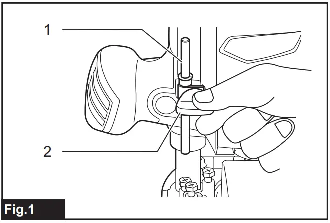
- Place the tool on a flat surface. Loosen the screw securing the stopper pole. ► Fig.1:
1. Stopper pole 2. Screw
- Loosen the lock lever and lower the tool body until the router bit just touches the flat surface. Tighten the lock lever to lock the tool body.
► Fig.2: 1. Lock lever 2. Screw
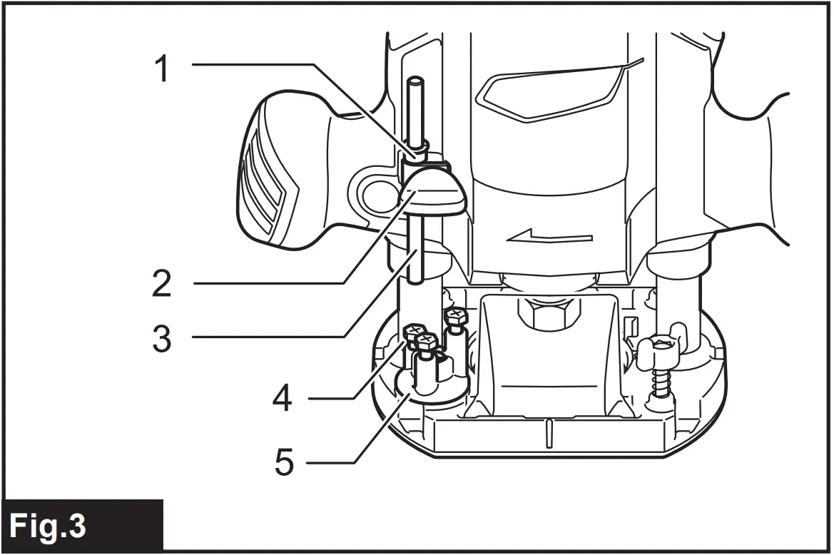
- Lower the stopper pole until it makes contact with the adjusting hex bolt. Align the depth pointer with the “0” graduation.
► Fig.3: 1. Depth pointer 2. Screw 3. Stopper pole Adjusting hex bolt 5. Stopper block - Raise the stopper pole until the desired depth of cut is obtained. The depth of cut is indicated on the scale (1 mm per graduation) by the depth pointer. Then tighten the screw to secure the stopper pole.
- Your predetermined depth of cut can be obtained by loosening the lock lever and then lowering the tool body until the stopper pole makes contact with the adjusting hex bolt.

Stopper block
The stopper block has three adjusting hex bolts which raise or lower 0.8 mm (approx. 1/32″) per turn. You can easily obtain three different depths of cut using these adjusting hex bolts without readjusting the stopper pole.
► Fig.4: 1. Depth pointer 2. Screw 3. Stopper pole 4. Adjusting hex bolt 5. Stopper block
- Adjust the lowest hex bolt to obtain the deepest depth of cut, following the method of “Adjusting the depth of cut”.
- Adjust the two remaining hex bolts to obtain shallower depths of cut. The differences in height of these hex bolts are equal to the differences in depths of cut.
- Turn the hex bolts to adjust the depth. The stopper block is also convenient for making three passes with progressively deeper bit settings when cutting deep grooves.
NOTE: When using a bit having total length of 60 mm (2-3/8″) or more, or edge length of 35 mm (1-3/8″) or more, the depth of cut cannot be adjusted as previously mentioned. To adjust, proceed as follows:
|
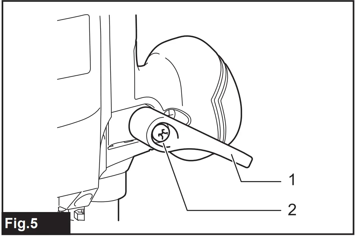
Adjusting the lock lever
The locked position of the lock lever is adjustable. To adjust it, remove the screw securing the lock lever. The lock lever will come off. Set the lock lever at the desired angle. After adjustment, tighten the lock lever clockwise.
► Fig.5: 1. Lock lever 2. Screw
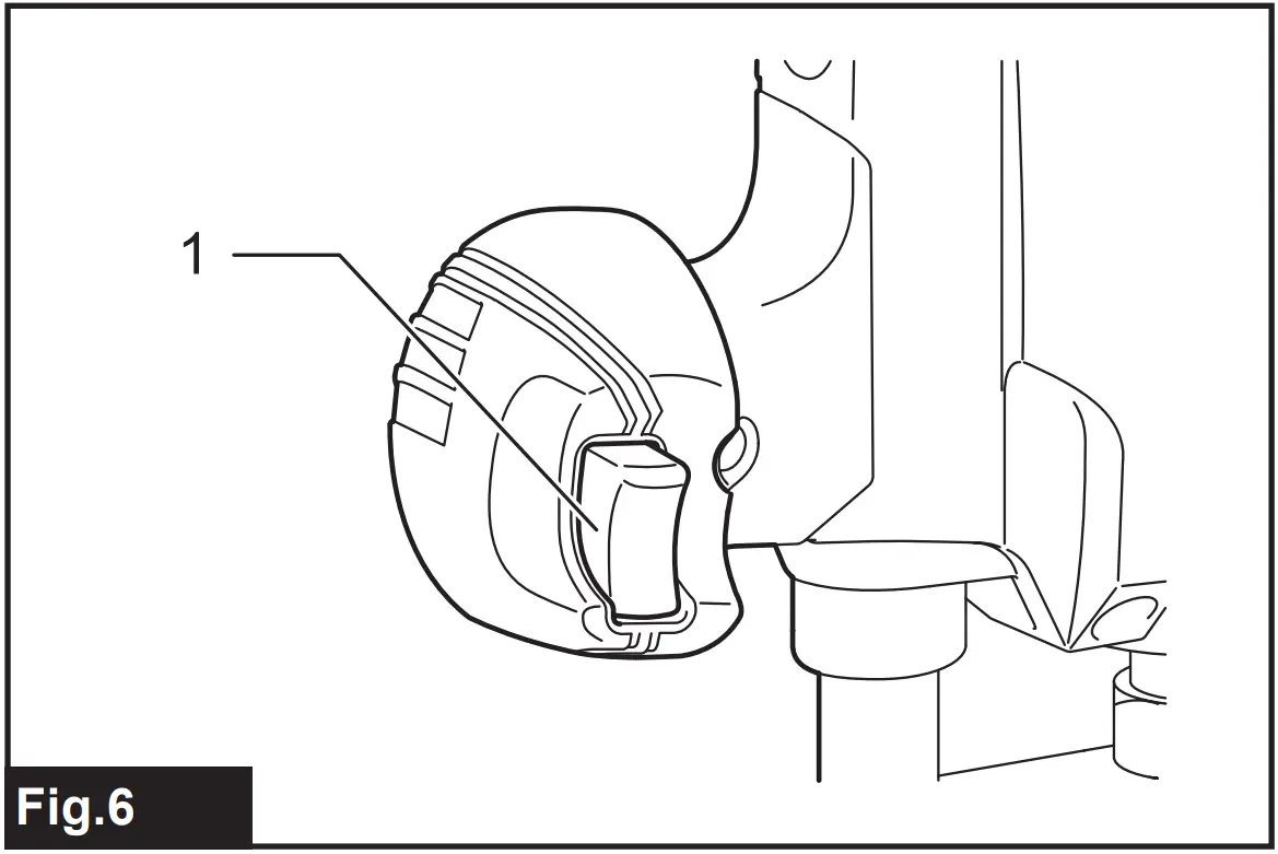
Switch action
To start the tool, simply pull the switch trigger. Release the switch trigger to stop.
► Fig.6: 1. Switch trigger
ASSEMBLY
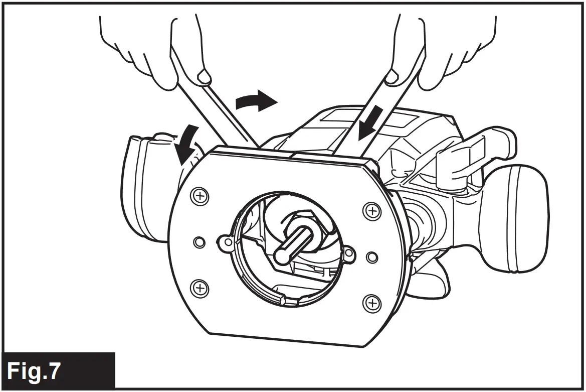
Installing or removing the router bit
Insert the bit all the way into the collet cone and tighten the collet nut securely with the two wrenches. Use the correct size collet cone for the bit which you intend to use.
To remove the bit, follow the installation procedure in reverse.
► Fig.7
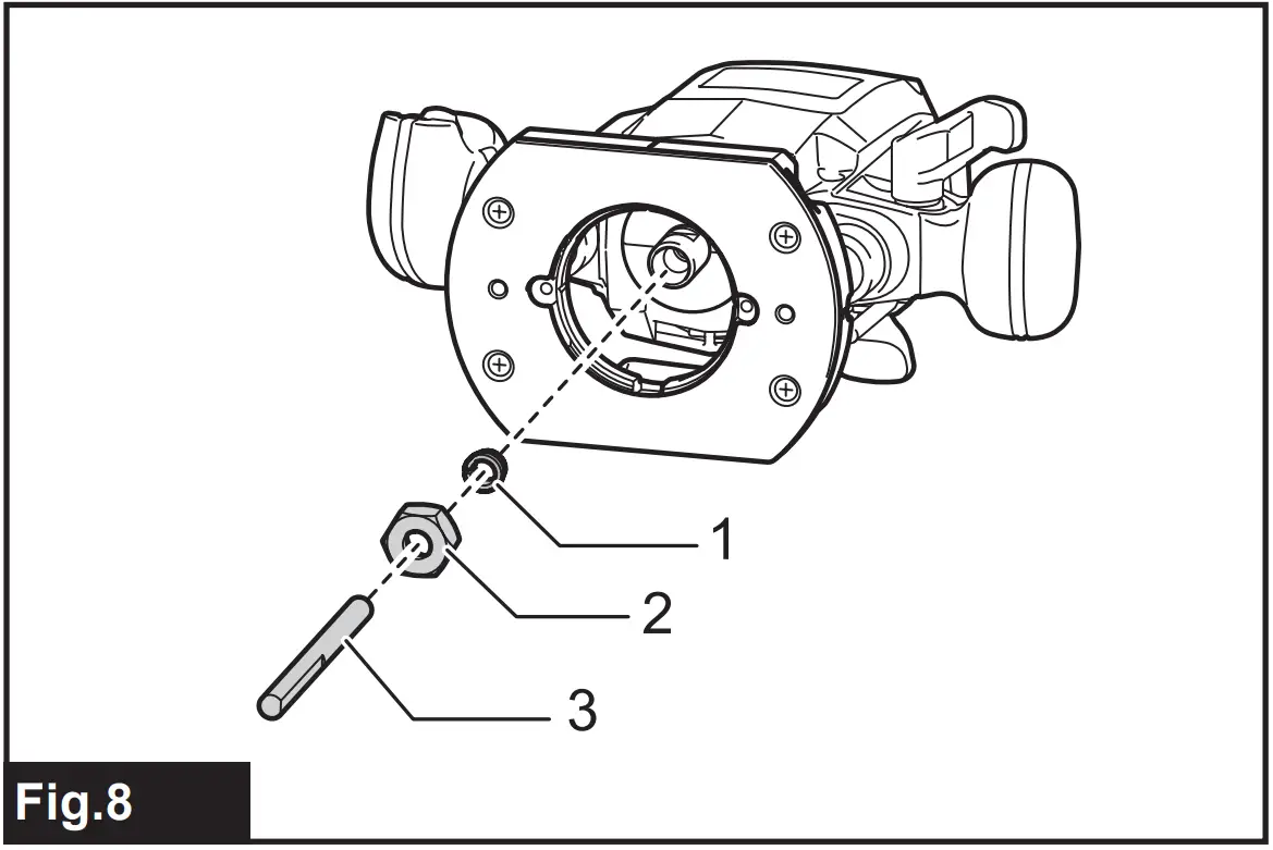
Changing the collet cone
Country specific
| NOTICE: Use the correct size collet cone for the bit that you are going to use. NOTICE: Do not tighten the collet nut without installing a bit, or the collet cone may break. |
► Fig.8: 1. Collet cone 2. Collet nut 3. Bit
To change the collet cone, loosen the collet nut and remove. Replace the installed collet cone with desired collet cone. Reinstall collet nut.
OPERATION
Set the tool base on the workpiece to be cut without the router bit making any contact. Then turn the tool on and wait until the router bit attains full speed. Lower the tool body and move the tool forward over the workpiece surface, keeping the tool base flush and advancing smoothly until the cutting is complete.
When doing edge cutting, the workpiece surface should be on the left side of the router bit in the feed direction.
► Fig.9:
1. Workpiece
2. Bit revolving direction
3. View from the top of the tool
4. Feed direction
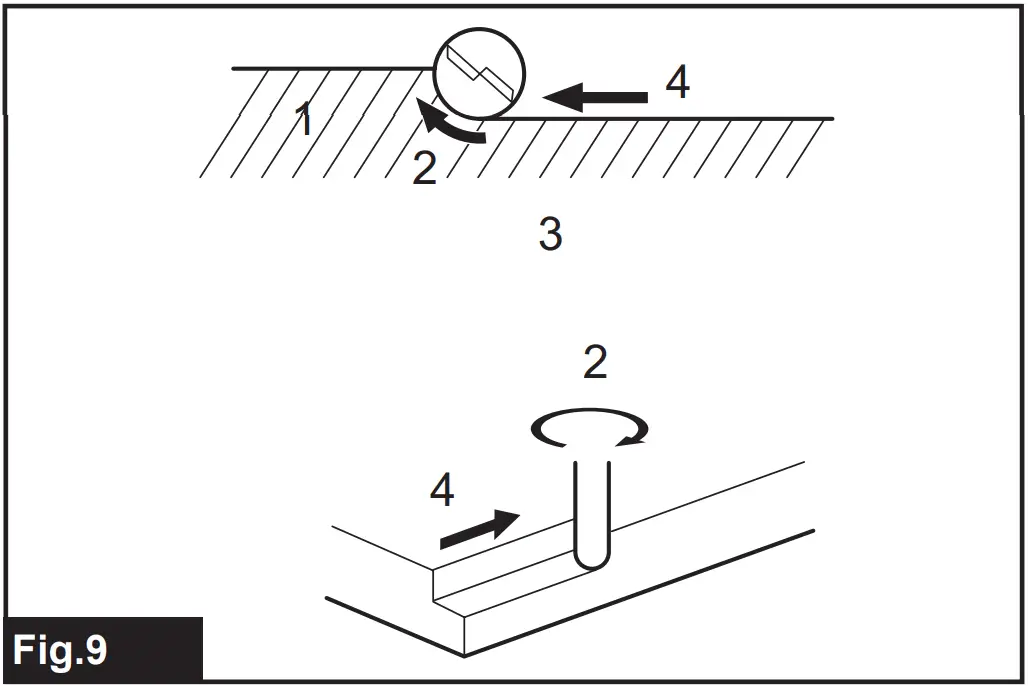
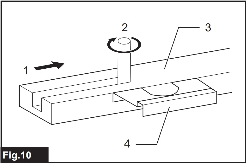
| NOTE: Moving the tool forward too fast may cause a poor quality of cut, or damage to the router bit or motor. Moving the tool forward too slowly may burn and mar the cut. The proper feed rate will depend on the router bit size, the kind of workpiece and depth of cut. Before beginning the cut on the actual workpiece, it is advisable to make a sample cut on a piece of scrap lumber. This will show exactly how the cut will look as well as enable you to check dimensions. NOTE: When using the straight guide or the trimmer guide, be sure to install it on the right side in the feed direction. This will help to keep it flush with the side of the workpiece |
► Fig.10:
1. Feed direction 2. Bit revolving direction 3. Workpiece 4. Straight guide
Straight guide
The straight guide is effectively used for straight cuts when chamfering or grooving.
► Fig.11
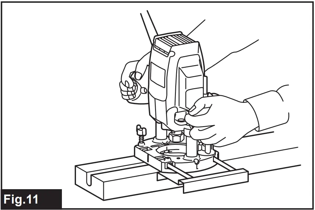
To install the straight guide, insert the guide bars into the holes in the tool base. Adjust the distance between the bit and the straight guide. At the desired distance, tighten the wing bolts to secure the straight guide in place. When cutting, move the tool with the straight guide flush with the side of the workpiece.
► Fig.12:
1. Guide bar 2. Clamp screw 3. Straight guide
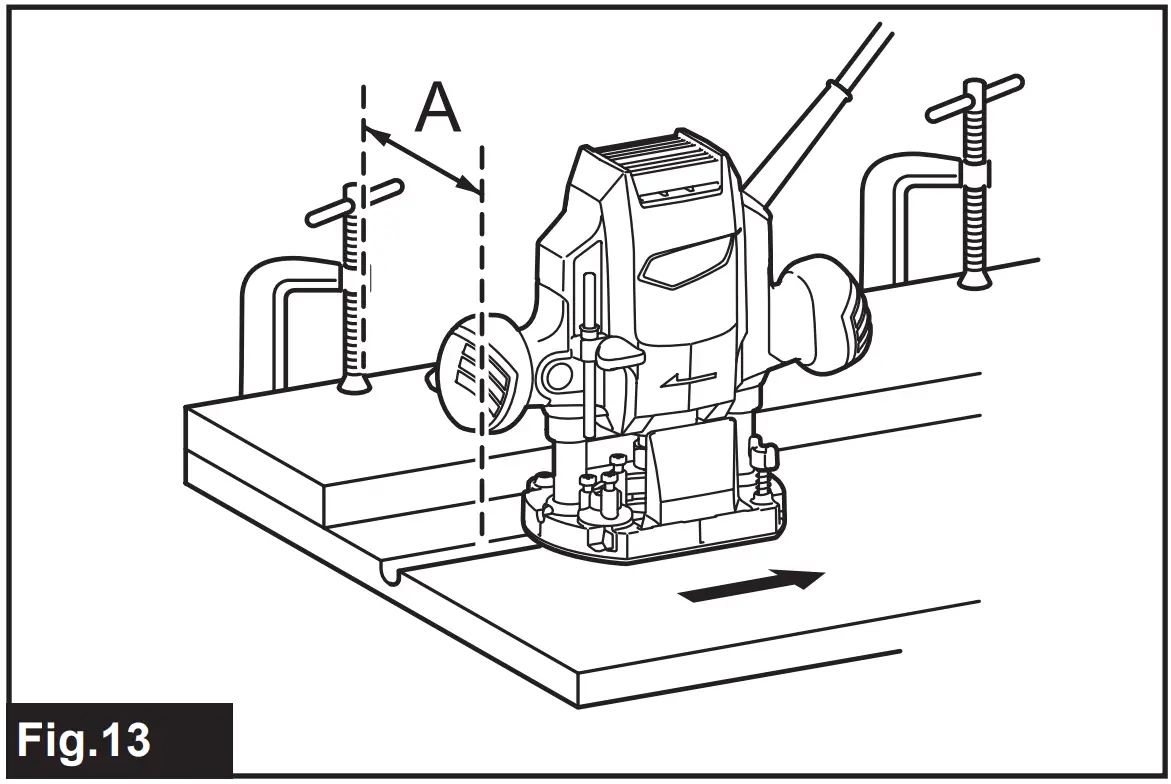
If the distance (A) between the side of the workpiece and the cutting position is too wide for the straight guide, or if the side of the workpiece is not straight, the straight guide cannot be used. In this case, firmly clamp a straight board to the workpiece and use it as a guide against the trimmer base. Feed the tool in the direction of the arrow.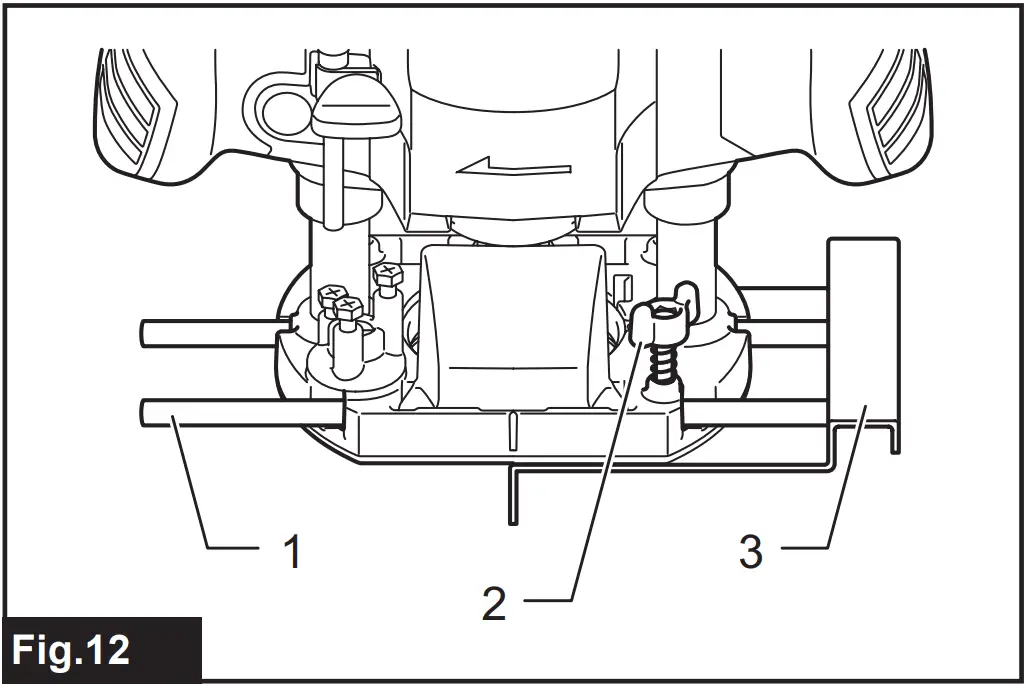
► Fig.13
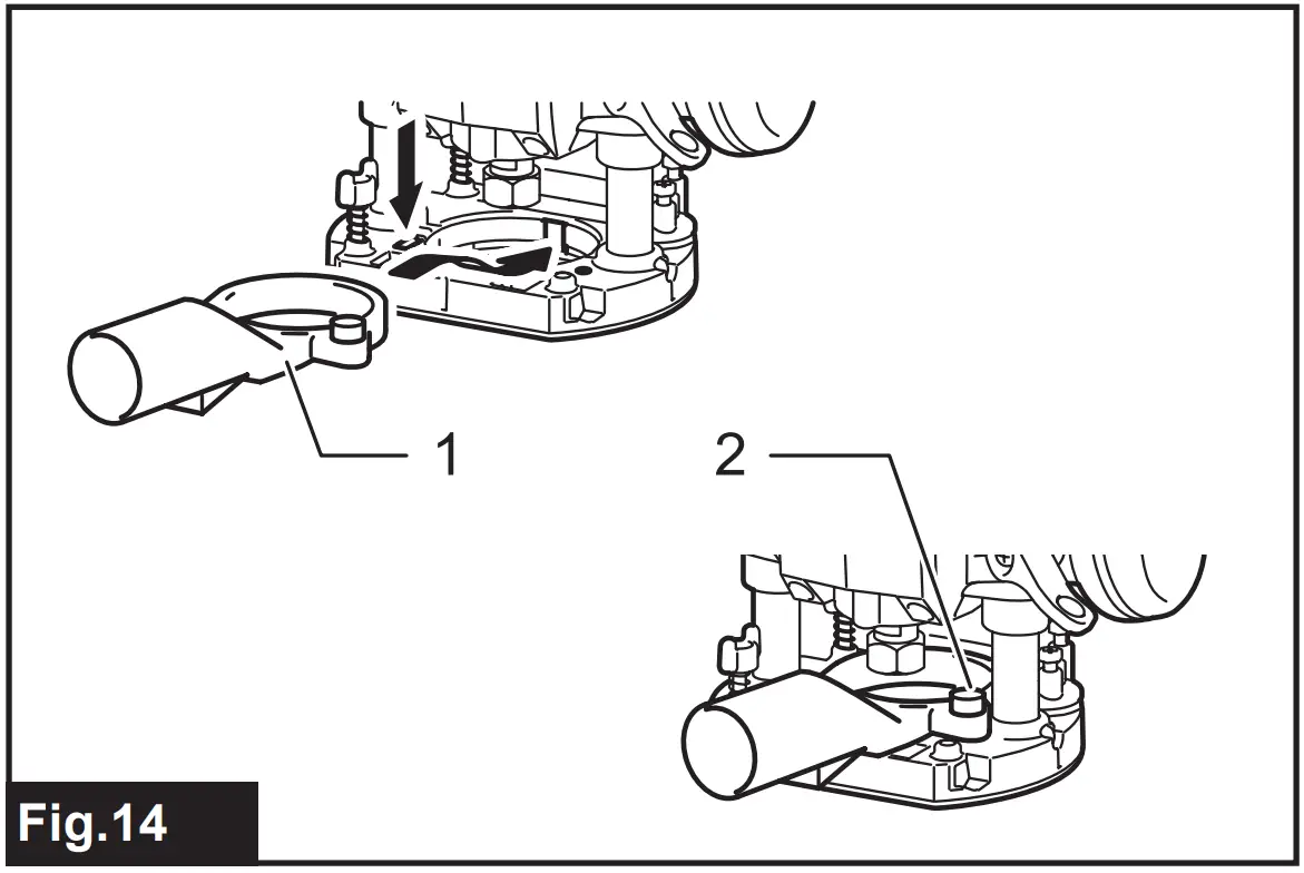
Dust nozzle set (country specific)
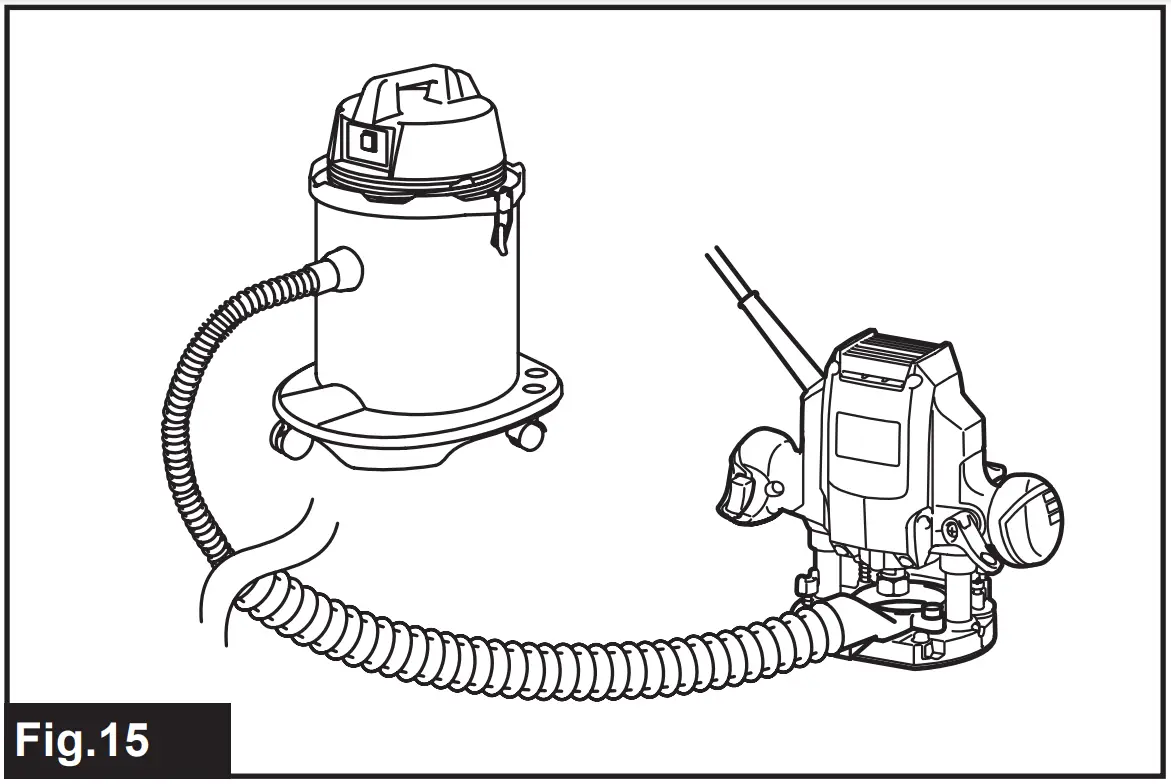
Use the dust nozzle for dust extraction. Install the dust nozzle on the tool base using the thumb screw so that protrusion on the dust nozzle fit to the notch in the tool base. Then connect a vacuum cleaner to the dust nozzle.
► Fig.14:
1. Dust nozzle
2. Thumb screw
► Fig.15
MAINTENANCE
| NOTICE: Never use gasoline, benzine, thinner, alcohol or the like. Discoloration, deformation or cracks may result. |
To maintain product SAFETY and RELIABILITY, repairs, any other maintenance or adjustment should be performed by Makita Authorized or Factory Service Centers, always using Makita replacement parts.
OPTIONAL ACCESSORIES
If you need any assistance for more details regarding these accessories, ask your local Makita Service
Center.
- Straight & groove forming bits
- Edge forming bits
- Laminate trimming bits
| NOTE: Some items in the list may be included in the tool package as standard accessories. They may differ from country to country |
Router bits
Straight bit
► Fig.16
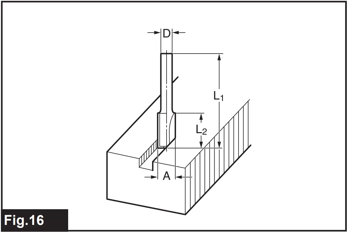
D | A | L1 | L2 |
6 | 20 | 50 | 15 |
| 1/4″ | |||
| 8 | 8 | 60 | 25 |
| 6 | 8 | 50 | 18 |
| 1/4″ | |||
| 6 | 6 | 50 | 18 |
| 1/4″ |
“U”Grooving bit
► Fig.17
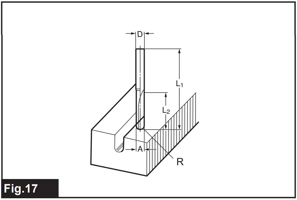
| D | A | L1 | L2 | R |
| 6 | 6 | 50 | 18 | 3 |
“V”Grooving bit
► Fig.18
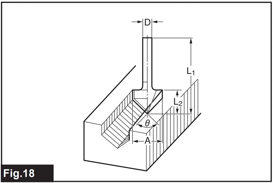
| D | A | L1 | L2 | θ |
| 1/4″ | 20 | 50 | 15 | 90° |
Drill point flush trimming bit
► Fig.19
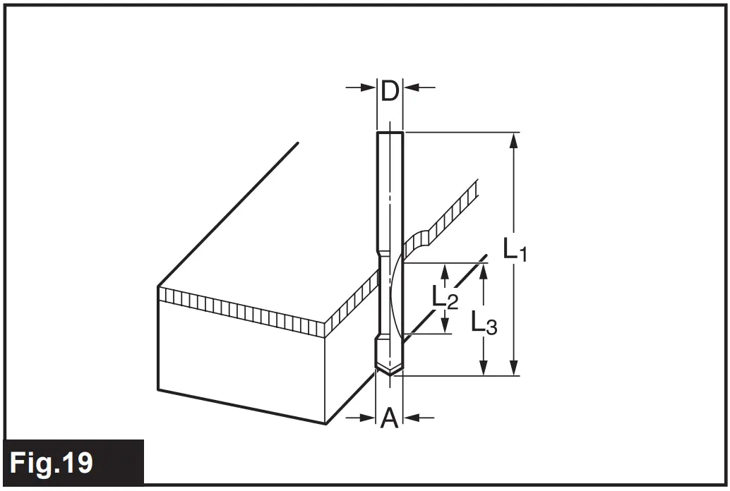
| D | A | L1 | L2 | L3 |
| 8 | 8 | 60 | 20 | 35 |
| 6 | 6 | 60 | 18 | 28 |
Drill point double flush trimming bit
► Fig.20
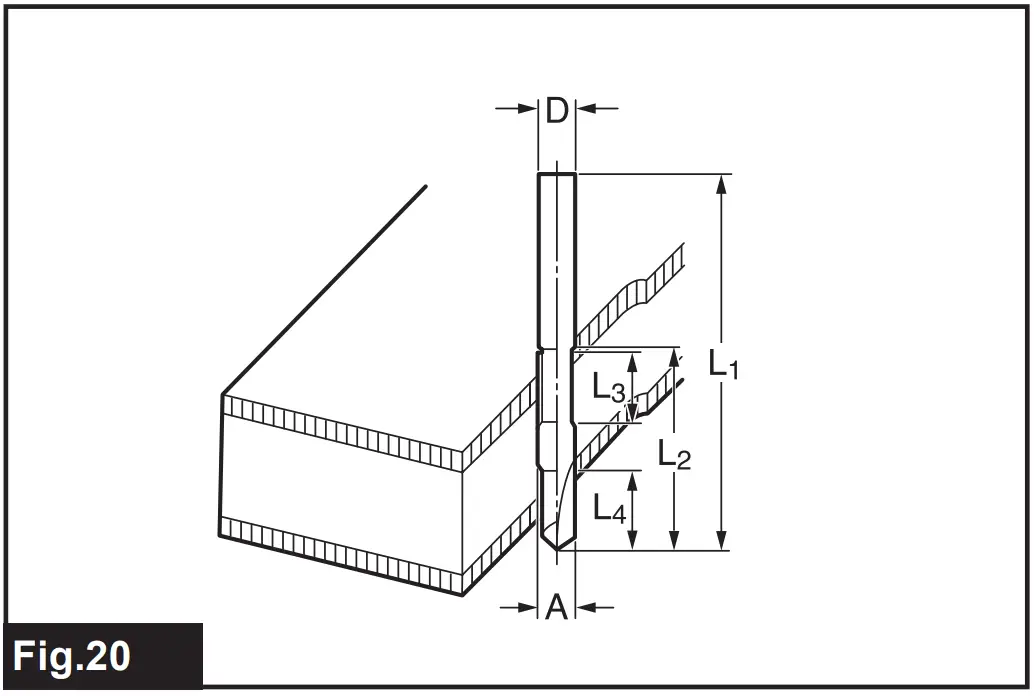
| D | A | L1 | L2 | L3 | L4 |
| 8 | 8 | 80 | 55 | 20 | 25 |
| 6 | 6 | 70 | 40 | 12 | 14 |
Corner rounding bit
► Fig.21
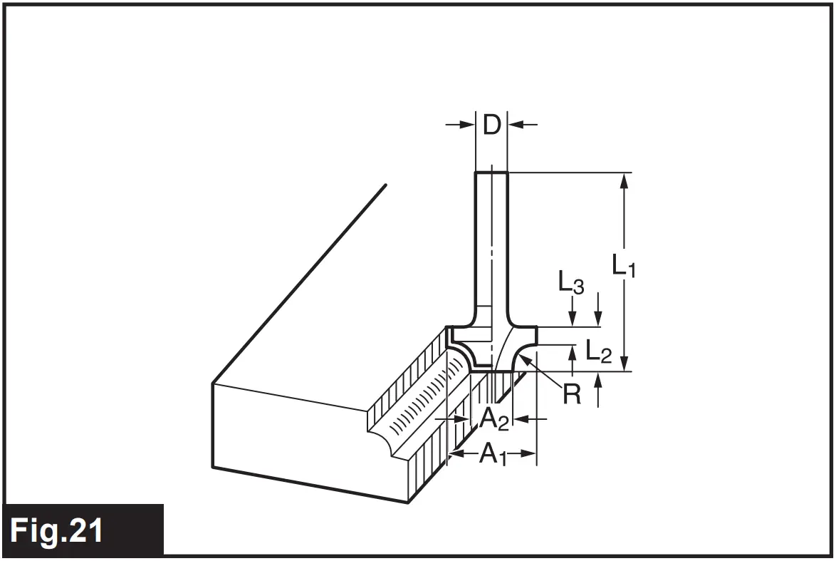
| D | A1 | A2 | L1 | L2 | L3 | R |
| 6 | 25 | 9 | 48 | 13 | 5 | 8 |
| 6 | 20 | 8 | 45 | 10 | 4 | 4 |
Chamfering bit
► Fig.22
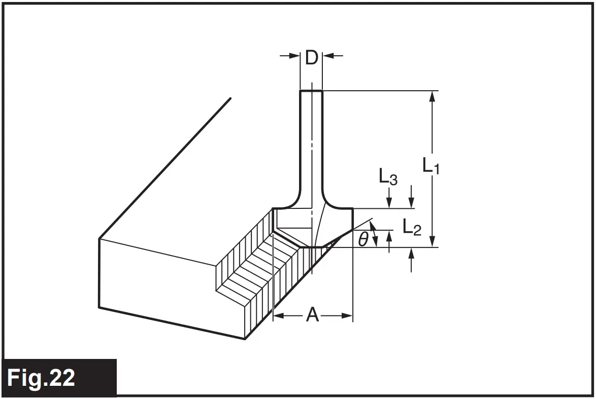
| D | A | L1 | L2 | L3 | θ |
| 6 | 23 | 46 | 11 | 6 | 30° |
| 6 | 20 | 50 | 13 | 5 | 45° |
| 6 | 20 | 49 | 14 | 2 | 60° |
Cove beading bit
► Fig.23
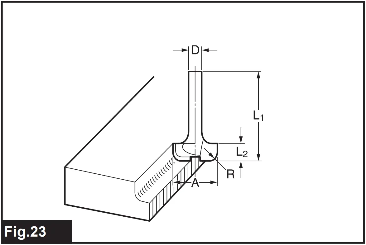
| D | A | L1 | L2 | R |
| 6 | 20 | 43 | 8 | 4 |
| 6 | 25 | 48 | 13 | 8 |
Ball bearing flush trimming bit
► Fig.24
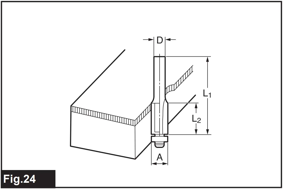
| D | A | L1 | L2 |
| 6 | 10 | 50 | 20 |
| 1/4″ |
Ball bearing corner rounding bit
► Fig.25
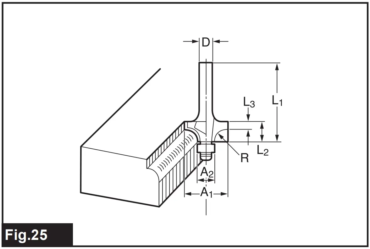
| D | A1 | A2 | L1 | L2 | L3 | R |
| 6 | 15 | 8 | 37 | 7 | 3.5 | 3 |
| 6 | 21 | 8 | 40 | 10 | 3.5 | 6 |
| 1/4″ | 21 | 8 | 40 | 10 | 3.5 | 6 |
Ball bearing chamfering bit
► Fig.26
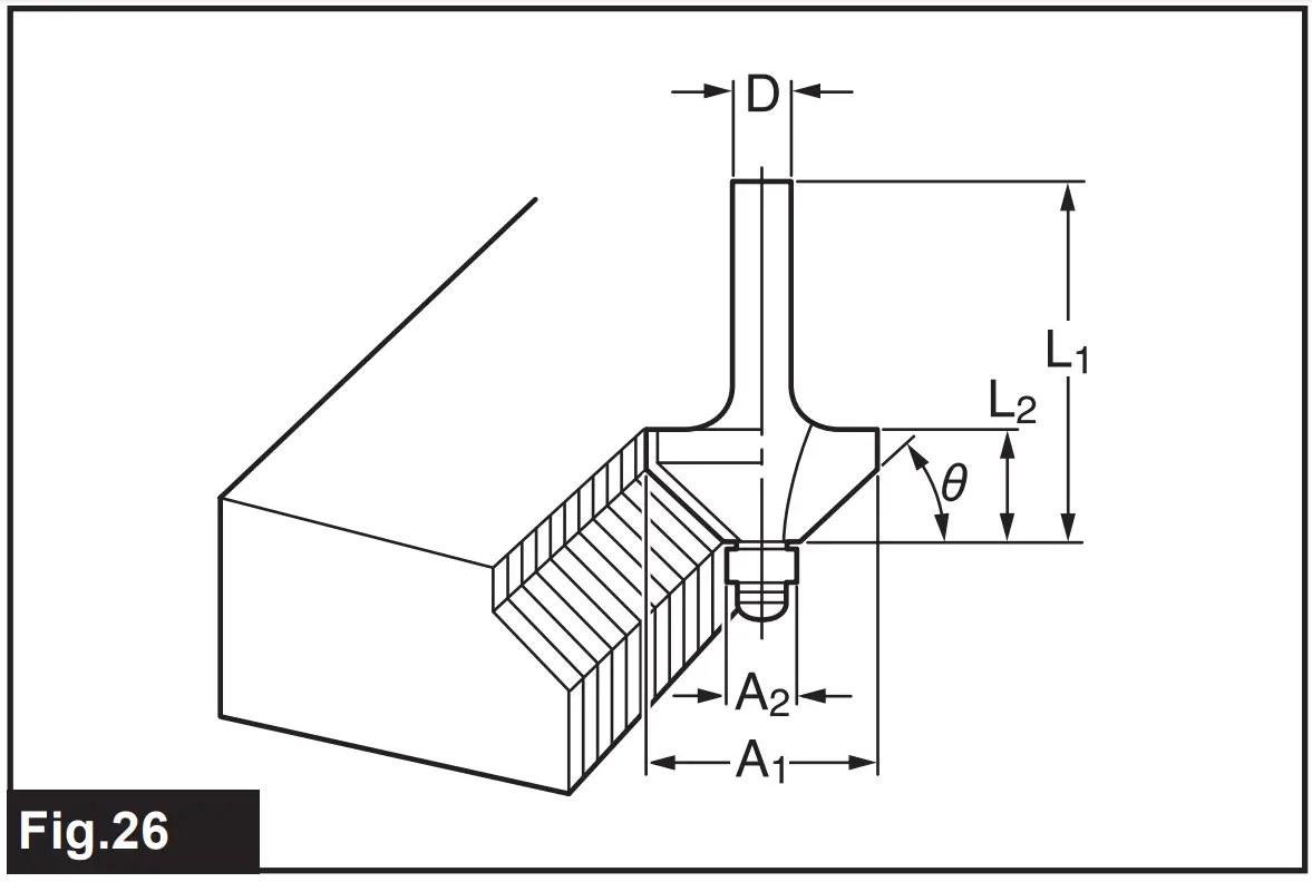
| D | A1 | A2 | L1 | L2 | θ |
| 6 | 26 | 8 | 42 | 12 | 45° |
| 1/4″ | |||||
| 6 | 20 | 8 | 41 | 11 | 60° |
Ball bearing beading bit
► Fig.27
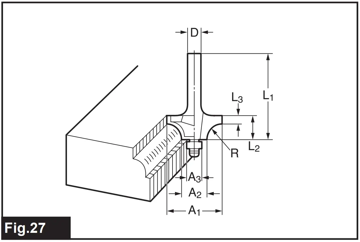
| D | A1 | A2 | A3 | L1 | L2 | L3 | R |
| 6 | 20 | 12 | 8 | 40 | 10 | 5.5 | 4 |
| 6 | 26 | 12 | 8 | 42 | 12 | 4.5 | 7 |
Ball bearing cove beading bit
► Fig.28
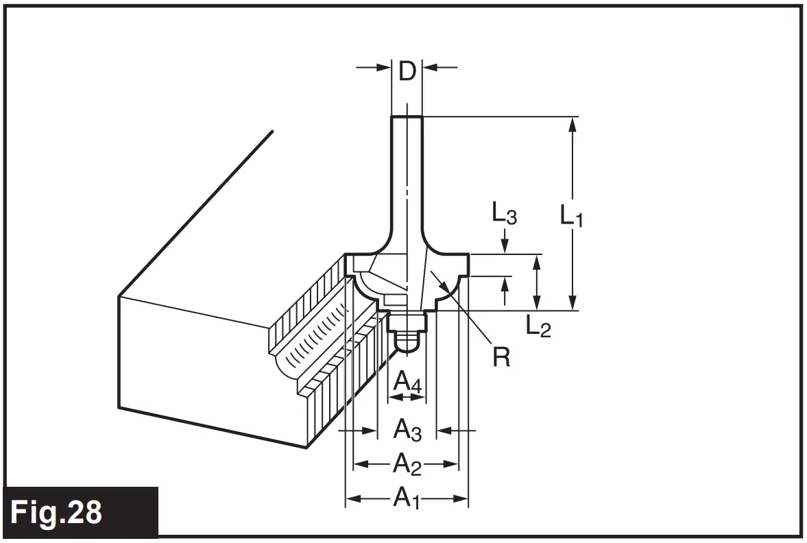
| D | A1 | A2 | A3 | A4 | L1 | L2 | L3 | R |
| 6 | 20 | 18 | 12 | 8 | 40 | 10 | 5.5 | 3 |
| 6 | 26 | 22 | 12 | 8 | 42 | 12 | 5 | 5 |
Ball bearing roman ogee bit
► Fig.29
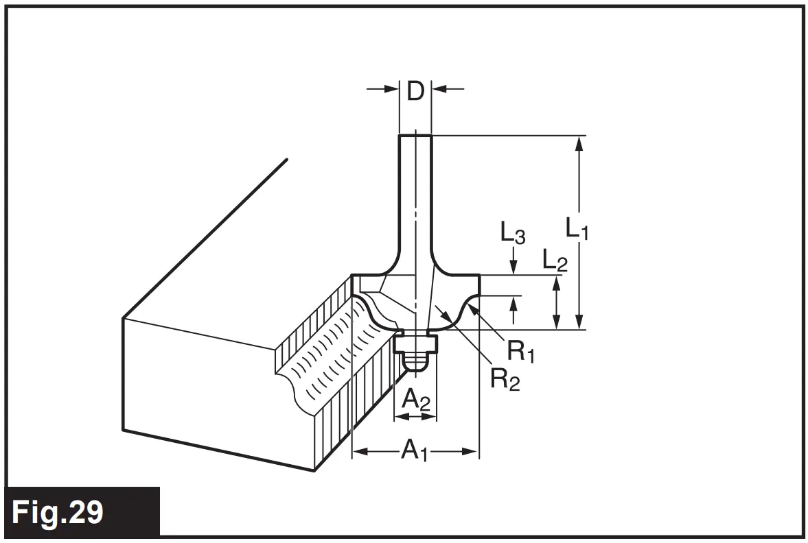
| D | A1 | A2 | L1 | L2 | L3 | R1 | R2 |
| 6 | 20 | 8 | 40 | 10 | 4.5 | 2.5 | 4.5 |
| 6 | 26 | 8 | 42 | 12 | 4.5 | 3 | 6 |
Makita Europe N.V
Jan-Baptist Vinkstraat 2,
3070 Kortenberg, Belgium
Makita Corporation
3-11-8, Sumiyoshi-cho, njo, Aichi 446-8502 Japan