VENTS MPA 800 E Series Supply Units User Manual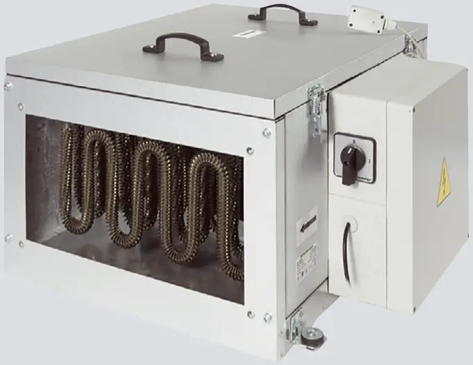
This user’s manual is a main operating document intended for technical, maintenance, and operating staff.
The manual contains information about purpose, technical details, operating principle, design, and installation of the MPA unit and all its modifications.
Technical and maintenance staff must have theoretical and practical training in the field of ventilation systems and should be able to work in accordance with workplace safety rules as well as construction norms and standards applicable in the territory of the country.
SAFETY REQUIREMENTS
All user’s manual requirements as well as the provisions of all the applicable local and national construction, electrical, and technical norms and standards must be observed when installing and operating the unit.
Disconnect the unit from the power supply prior to any connection, servicing, maintenance, and repair operations.
Only qualified electricians with a work permit for electrical units up to 1000 V are allowed for installation. The present user’s manual should be carefully read before beginning works.
Check the unit for any visible damage of the impeller, the casing, and the grille before starting installation. The casing internals must be free of any foreign objects that can damage the impeller blades.
While mounting the unit, avoid compression of the casing! Deformation of the casing may result in motor jam and excessive noise.
Misuse of the unit and any unauthorised modifications are not allowed.
Do not expose the device to adverse atmospheric agents (rain, sun, etc.).
Transported air must not contain any dust or other solid impurities, sticky substances, or fibrous materials.
Do not use the unit in a hazardous or explosive environment containing spirits, gasoline, insecticides, etc.
Do not close or block the intake or extract vents in order to ensure the efficient air flow.
Do not sit on the unit and do not put objects on it.
The information in this user’s manual was correct at the time of the document’s preparation.
The Company reserves the right to modify the technical characteristics, design, or configuration of its products at any time in order to incorporate the latest technological developments.
Never touch the unit with wet or damp hands.
Never touch the unit when barefoot.
This appliance is not intended for use by persons (including children) with reduced physical, sensory or mental capabilities, or lack of experience and knowledge, unless they have been given supervision or instruction concerning use of the appliance by a person responsible for their safety.
Children should be supervised to ensure that they do not play with the appliance.
This appliance incorporates an earth connection for functional purposes.
The connection to the supply mains must be made through a means of disconnection, which is incorporated in the fixed wiring in accordance with the wiring rules, and has a contact separation in all poles that allows for full disconnection under overvoltage category III conditions.
If the supply cord is damaged, it must be replaced by the manufacturer, its service agent, or similarly qualified persons in order to avoid a safety hazard.
CAUTION: In order to avoid a safety hazard due to inadvertent resetting of the thermal cut-out, this appliance must not be supplied through an external switching device, such as a timer, or connected to a circuit that is regularly switched on and off by the utility.
Ensure that the appliance is switched off from the supply mains before removing the guard.
WARNING: If there are any unusual oscillating movements, immediately stop using the appliance and contact the manufacturer, its service agent or suitably qualified persons.
The replacement of parts of the safety suspension system device shall be performed by the manufacturer, its service agent or suitably qualified persons.
Fixing means for attachment to the ceiling such as hooks or other devices shall be fixed with a sufficient strength to withstand 4 times the weight of the appliance.
The mounting of the suspension system shall be performed by the manufacturer, its service agent or suitably qualified persons.
The appliance is to be installed so that the blades are more than 2.3m above the floor.
Precautions must be taken to avoid the back-flow of gases into the room from the open flue of gas or other fuel-burning appliances.
 THE PRODUCT MUST BE DISPOSED SEPARATELY AT THE END OF ITS SERVICE LIFE.
DO NOT DISPOSE THE UNIT AS UNSORTED DOMESTIC WASTE.
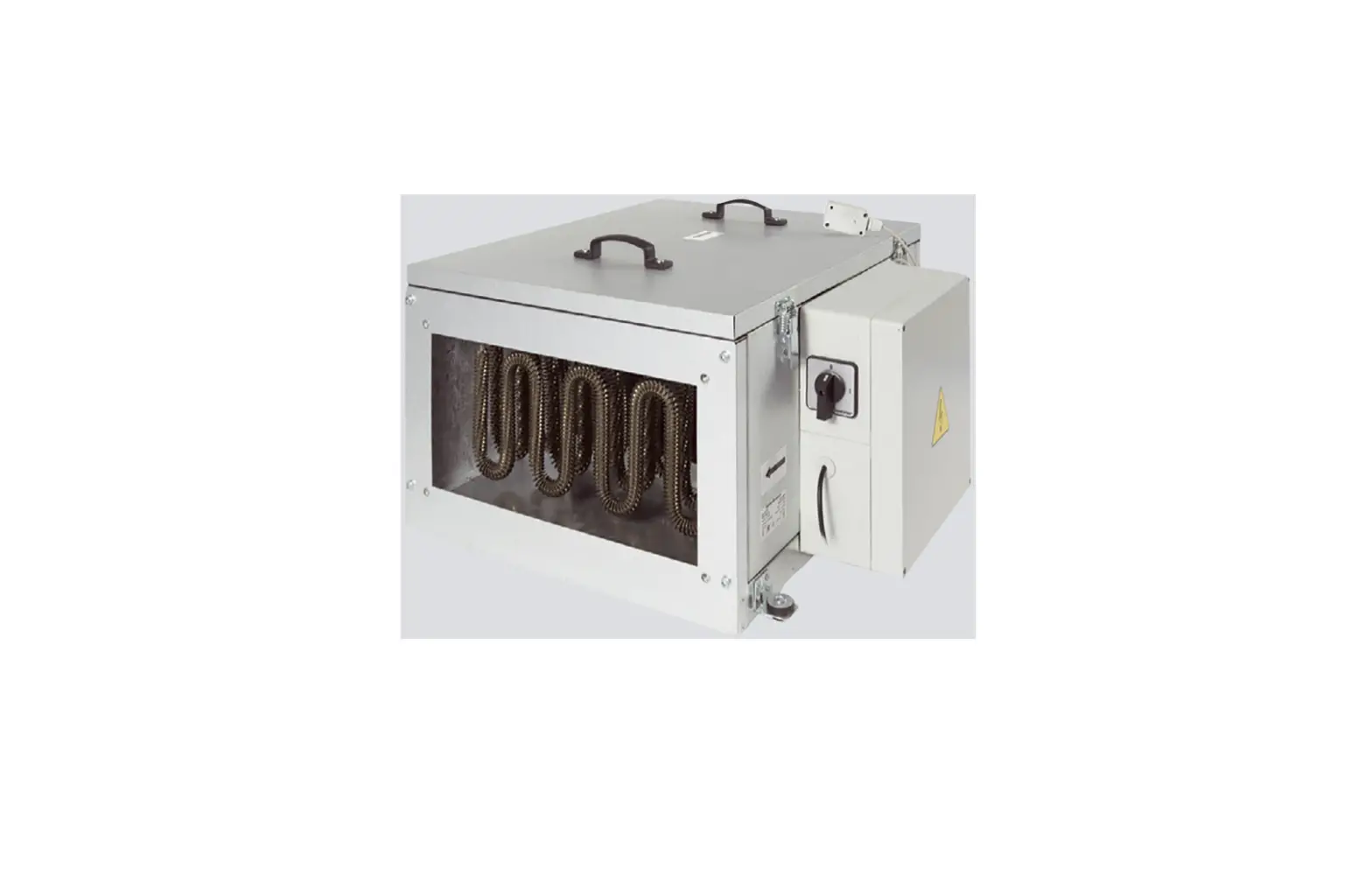
PURPOSE
The unit is intended for filtering, supplying and heating purified intake air in private homes, offices, hotels, cafés, conference halls and other residential and public spaces.
The unit is a component part and is not designed for stand-alone operation.
The unit is rated for continuous operation.
Transported air must not contain any flammable or explosive mixtures, evaporation of chemicals, sticky substances, fibrous.
 THE UNIT SHOULD NOT BE OPERATED BY CHILDREN OR PERSONS WITH REDUCED PHYSICAL, MENTAL, OR SENSORY CAPACITIES, OR THOSE WITHOUT THE APPROPRIATE TRAINING.
THE UNIT MUST BE INSTALLED AND CONNECTED ONLY BY PROPERLY QUALIFIED PERSONNEL AFTER THE APPROPRIATE BRIEFING.
THE CHOICE OF UNIT INSTALLATION LOCATION MUST PREVENT UNAUTHORISED ACCESS BY UNATTENDED CHILDREN.
materials, coarse dust, soot and oil particles or environments favourable for the formation of hazardous substances (toxic substances, dust, pathogenic germs).
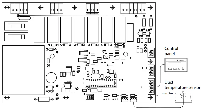
The unit can be equipped with an adapted automation kit, which includes: a control panel, a control unit, an optotriac to control heater, a duct temperature sensor, and a differential pressure sensor.
The use of an automation kit allows controlling air flow, temperature (heating), and air filtration, which can significantly save energy.
DELIVERY SET
NAME/NUMBER
Air handling unit 1 pc.
Control panel (for models with automation) 1 pc.
Duct temperature sensor 1 pc.
User’s manual 1 pc.
Packing box 1 pc.
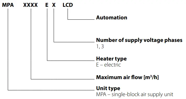
DESIGNATION KEY
TECHNICAL DATA
The unit is designed for indoor application with the ambient temperature ranging from +1 °C up to +40 °C and relative humidity up to 80 % without condensation.
The unit should be operated continuously, and in cases where ventilation is not necessary, reduce the air flow of the fans to a minimum (20%). This will ensure a favorable indoor climate and reduce the amount of condensation inside the unit, which can damage electronic components. Never use the unit for dehumidification, for example, of new buildings.
The unit is rated as a Class I electrical appliance.
Hazardous parts access and water ingress protection rating:
IP22 for the unit connected to the air ducts
IP44 for the unit motors
The unit design is constantly being improved, thus some models may be slightly different from those described in this manual.
THE OVERALL AND CONNECTION DIMENSIONS OF MPA UNIT
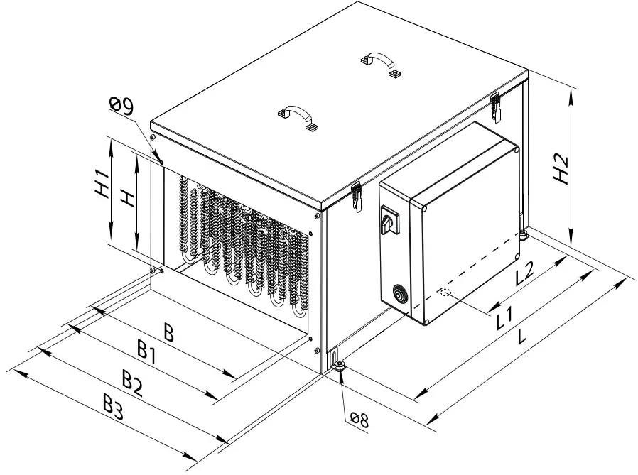
| Model | В | В1 | В2 | ВЗ | Н | Н1 | Н2 | L | L1 | L2 |
| MPA 800 Е1 | 400 | 420 | 549 | 500 | 200 | 220 | 352 | 650 | 530 | – |
| MPA 1200 ЕЗ | 400 | 420 | 549 | 500 | 200 | 220 | 352 | 650 | 530 | – |
| MPA 1800 ЕЗ | 500 | 520 | 649 | 600 | 250 | 270 | 480 | 800 | 680 | – |
| MPA 2500 ЕЗ | 500 | 520 | 649 | 600 | 300 | 320 | 480 | 800 | 680 | – |
| MPA 3200 ЕЗ | 600 | 620 | 759 | 710 | 300 | 320 | 530 | 1000 | 880 | 440 |
| MPA 3500 ЕЗ | 600 | 620 | 759 | 710 | 350 | 370 | 530 | 1000 | 880 | 440 |
MAIN TECHNICAL PARAMETERS
| Model | Voltage [V] at 50 Hz | Number of phases | Heater power [kW] | Heater current [A] | Number of electric heating elements [pcs] | Fan power [W] | Fan current [A] | RPM [min-1] | Air flow [m3/h] | Sound pressure level at 3 m distance [dBA] | Weight [kg] | Maximum ambient air temperature [°C] |
| MPA 800 Е1 | 230 | 1 | 3.3 | 14.3 | 1 | 245 | 1.08 | 1650 | 800 | 35 | 36.2 | 45 |
| MPA 1200 ЕЗ | 400 | 3 | 9.9 | 14.3 | 3 | 410 | 1.8 | 1850 | 1200 | 38 | 38.9 | 45 |
| MPA 1800 ЕЗ | 400 | 3 | 18.0 | 26.0 | 3 | 490 | 2.15 | 1100 | 1800 | 40 | 61.5 | 45 |
| MPA 2500 ЕЗ | 400 | 3 | 18.0 | 26.0 | 3 | 650 | 2.84 | 1000 | 2500 | 45 | 62 | 45 |
| MPA 3200 ЕЗ | 400 | 3 | 25.2 | 36.4 | 6 | 1270 | 2.3 | 1200 | 3200 | 53 | 69.4 | 45 |
| MPA 3500 ЕЗ | 400 | 3 | 25.2 | 36.4 | 6 | 1270 | 2.3 | 1200 | 3500 | 53 | 69.3 | 45 |
DESIGN AND OPERATING PRINCIPLE
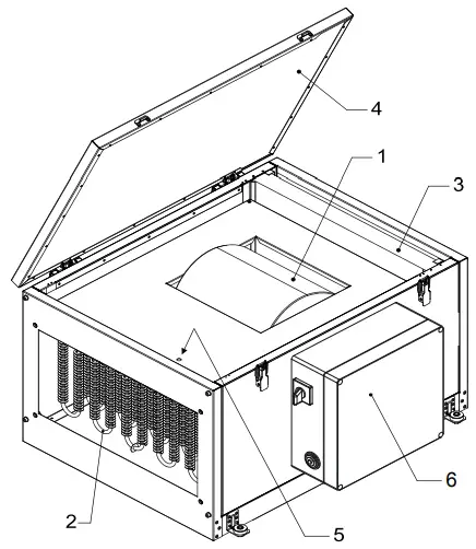
The unit allows controlling the air flow, air temperature (preheating) and air filtering.
- Air flow can be adjusted by controlling the fan speed.
- Air heating is provided by an integrated electric heater (item 2).
- The unit is equipped with an air filter with filtering class G4 (item З).
- Hinged (item 4) or removable cover optimally uses the space for installation.
- Unit design allows standard connection to rectangular air ducts of the duct work.
- The unit is equipped with two sensors-thermal switches: one is a safety thermal switch with automatic restart, and the second one is an emergency thermal switch with manual restart when the RESET button is pressed (pos. 5).
MOUNTING AND SET-UP
READ THE USER’S MANUAL PRIOR TO MOUNTING THE UNIT.
The unit should be mounted so that the arrow on the cover coincides with air flow direction in the system in order to provide access for maintenance, servicing or replacement work.
Enough space must be provided for the cover to open all the way.
The unit can be mounted on flat surface or suspended on a threaded rod ensuring a secure fixation to prevent unit detachment or falling down (in consideration of the unit weight and the mating surface material) using all the available L-shaped support brackets with an antivibration damper attached to the unit base.
The unit is designed for mounting into rectangular air ducts.
- The duct should be connected via a flexible connection to eliminate transfer of noise and random vibrations.
- The dimensions of the connected air duct must be the same as the dimensions of the hole in the unit.
The recommended distance between the unit and other elements of the system must be not less than the diagonal of the unit spigot (the distance from corner to corner of its air duct part).
CONNECTION TO POWER MAINS
DISCONNECT THE UNIT FROM POWER MAINS PRIOR TO ANY OPERATIONS. THE UNIT MUST BE CONNECTED TO POWER MAINS BY A QUALIFIED ELECTRICIAN. THE RATED ELECTRICAL PARAMETERS OF THE UNIT ARE GIVEN ON THE MANUFACTURER’S LABEL.
ANY TAMPERING WITH THE INTERNAL CONNECTIONS IS PROHIBITED AND WILL VOID THE WARRANTY.
- The unit is rated for connection to 1~220-240 V/50 (60) Hz or 3~400 V/50 Hz power mains according to the wiring diagram.
- The connection must be made using durable, insulated and heat esistant conductors (cables, wires). The conductor crosssection selection shall be based on maximum permissible current and maximum permissible wire heating, which depends on its type, insulation, length and installation method.
- The external power input must be equipped with an automatic circuit breaker QF built into the stationary wiring to open the circuit in the event of overload or short-circuit. The position of the external automatic circuit breaker must ensure free access for quick power-off of the unit. The automatic circuit breaker nominal current must exceed the ventilator current consumption, see the Technical data section or the unit label. It is recommended to select the nominal current of the circuit breaker from the standard series, following the maximum current of the connected unit. The circuit breaker is not included in the delivery set and can be ordered separately.
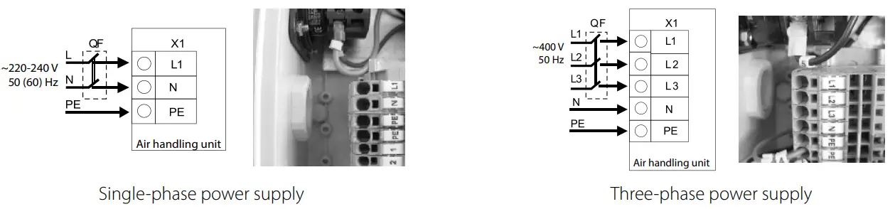
QF – external circuit breaker
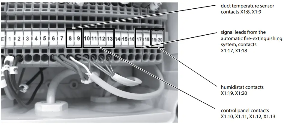
XI – terminal block for connecting the wires of the power supply network, as well as external devices – sensors, damper actuator, control panel, etc.
The automatic circuit breaker location must ensure free access for quick shutdown of the unit.
The required number of wires, their cross-section (mm²), as well as the ratings of the circuit breakers are shown in the table.
| Model | Rated current of the circuit breaker | Copper wire cross section |
| MPA 800 E1 | 230 V, 20 A | 3×2.5 |
| MPA 1200 EЗ | 400 V, 20 A | 5×2.5 |
| MPA 1800 EЗ | 400 V, 40 A | 5×6.0 |
| MPA 2500 EЗ | 400 V, 40 A | 5×6.0 |
| MPA 3200 EЗ | 400 V, 50 A | 5×10 |
| MPA 3500 EЗ | 400 V, 50 A | 5×10 |
The wire cross sections given in the table are for reference only!
Their selection shall be based on maximum permissible wire heating, which depends on its type, insulation, maximum permissible current, length of the lead wire and its location (air, wall).
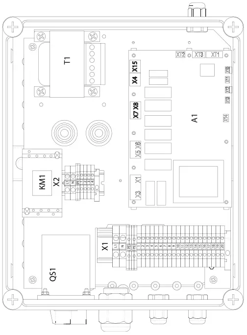
CONNECTION OF EXTERNAL DEVICES FOR MPA 800-2500
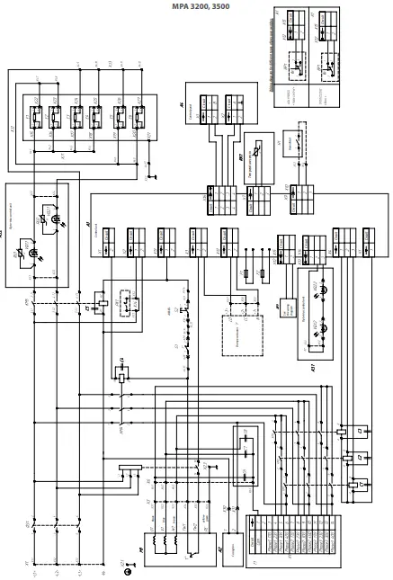
CONTROL BOARD MPA-3200-3500
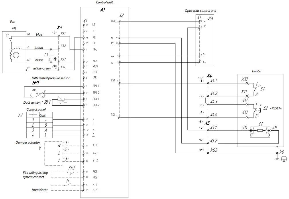
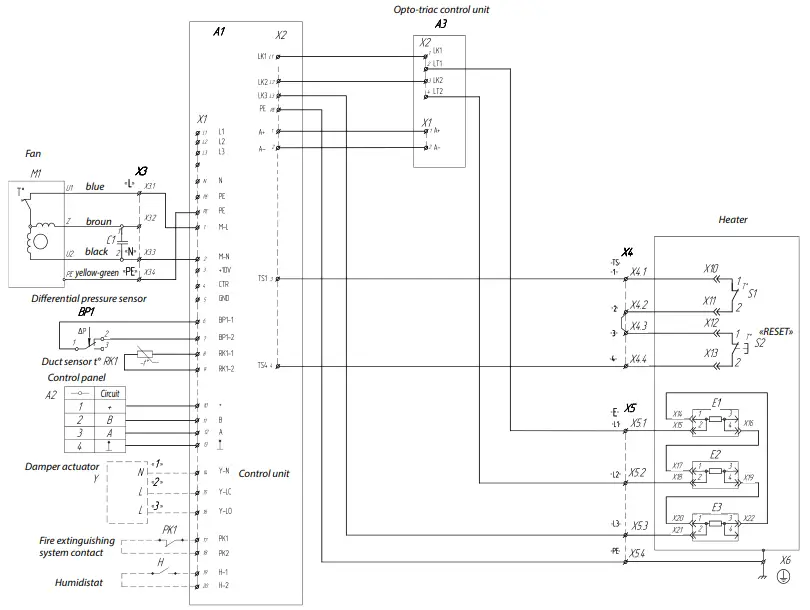
GENERAL VIEW AND WIRING DIAGRAMS OF CONTROL UNITS AND EXTERNAL DEVICES MPA 800
MPA 1200
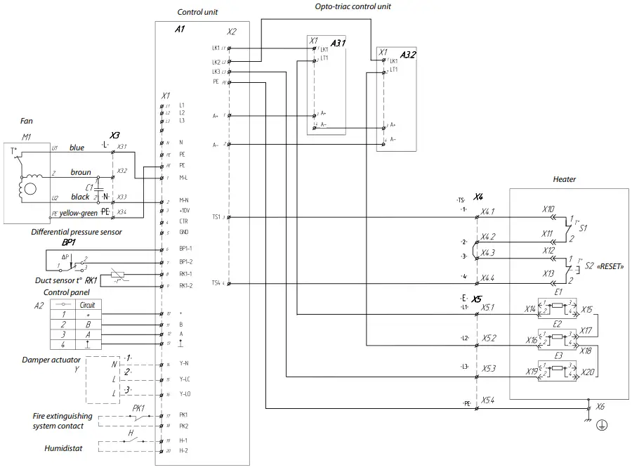
MPA 1800, 2500
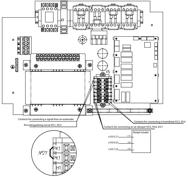
Additional options for external connections through the X5 terminal block are provided:
- connecting a contact of the automatic fire extinguishing system (inscription on the label – «PK1»)
- connecting a humidity sensor contact – humidistat (inscription on the label – «H1»)
- connecting a three-position air damper (inscription on the label – «1», «2», «3»).
When connecting the contact of the automatic fire extinguishing system, remove the jumper between the X5:1 and X5:2 terminals of the X5 terminal block. In this case, a normally closed «dry contact» is used, which when triggered in case of fire, opens the unit control circuit from the fire alarm panel and de-energizes it.
The humidistat is connected to the X5:3 and X5:4 terminals of the X5 terminal block. Normally open «dry contact» is used. When it is closed, the unit switches to maximum speed.
The air damper actuator is connected to the X5:5, X5:6, and X5:7 terminals; «M» (1) contact of the damper actuator – to the X5:5 terminal (inscription on the sticker «1»); «L» (2) contact – to the X5:6 terminal (inscription «2»); «L» (3) contact – to the Х5:7 terminal (inscription «3»).
The recommended type of damper is KRA (for round or rectangular air ducts) with an LM 230 A actuator (Belimo).
MPA-800 CONTROL UNIT
MPA-1200-2500 CONTROL UNIT
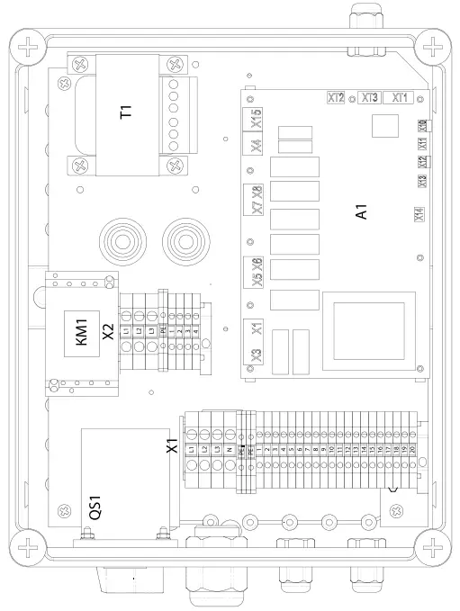
X1 TERMINAL BLOCK OF MPA-800 CONTROL UNIT
| Terminal marking | Circuit | External connection |
| L1 | L1 | Power supply ~ 230 V |
| N | N | Power supply ~ 230 V |
| РЕ | РЕ | Protective grounding |
| РЕ | РЕ | Protective grounding |
| 1 | M-L | Motor – line |
| 2 | M-N | Motor – neutral |
| 3 | +10V | Control circuit EC motor |
| 4 | CTR | Control circuit EC motor |
| 5 | GND | Control circuit EC motor |
| б | ВР1-1 | Differential pressure sensor |
| 7 | ВР1-2 | Differential pressure sensor |
| 8 | RK1-1 | Temperature sensor |
| 9 | RK1-2 | Temperature sensor |
| 10 | + | Control panel |
| 11 | В | Control panel |
| 12 | А | Control panel |
| 13 | Control panel | |
| 14 | Y-N | Damper actuator |
| 15 | Y-LC | Damper actuator |
| 16 | Y-LO | Damper actuator |
| 17 | РК1 | Normally closed contact of fire alarm system |
| 18 | РК2 | Normally closed contact of fire alarm system |
| 19 | Н-1 | Normally open contact of humidistat |
| 20 | Н-2 | Normally open contact of humidistat |
X1 TERMINAL BLOCK OF MPA-1200-2500 CONTROL UNIT
| Terminal marking | Circuit | External connection |
| L1 | L1 | Power supply ~ 400 V |
| L2 | L2 | Power supply ~ 400 V |
| L3 | L3 | Power supply ~ 400 V |
| N | N | Neutral |
| РЕ | РЕ | Protective grounding |
| РЕ | РЕ | Protective grounding |
| 1 | M-L | Motor – line |
| 2 | M-N | Motor – neutral |
| 3 | +10V | Control circuit EC motor |
| 4 | CTR | Control circuit EC motor |
| 5 | GND | Control circuit EC motor |
| б | ВР1-1 | Differential pressure sensor |
| 7 | ВР1-2 | Differential pressure sensor |
| 8 | RK1-1 | Temperature sensor |
| 9 | RK1-2 | Temperature sensor |
| 10 | + | Control panel |
| 11 | В | Control panel |
| 12 | А | Control panel |
| 13 | – | Control panel |
| 14 | Y-N | Damper actuator |
| 15 | Y-LC | Damper actuator |
| 16 | Y-LO | Damper actuator |
| 17 | РК1 | Normally closed contact of fire alarm system |
| 18 | РК2 | Normally closed contact of fire alarm system |
| 19 | Н-1 | Normally open contact of humidistat |
| 20 | Н-2 | Normally open contact of humidistat |
UNIT CONTROL
The unit is controlled using a remote control panel.
FUNCTIONAL CAPABILITIES
The system allows you to control the performance of the supply fan and has 3 speed levels:
- minimal ventilation, used on weekends and holidays in non residential premises or at night in residential premises
- normal ventilation
- increased ventilation when additional air flow is required
The device has the function of maintaining air temperature by a duct sensor or by a sensor in the control panel.
The duct temperature sensor enables the system to select the most suitable operation mode of the electric heating elements for maintaining a pre-set air temperature in the air duct.
The control panel is also equipped with a temperature sensor thereby allowing the maintenance of the set (user-defined) indoor temperature at the selected fan speed.
The optimal energy-saving program calculates the heater power required to sustain the indoor temperature with up to 1 °C accuracy while adjusting the heater power with up to 1 % accuracy.
The system status monitoring program monitors the unit operating parameters and, in the event of dangerous situations (overheating of the heating elements, critical filter clogging, communication line break), initiates emergency shutdown and sends corresponding signals to the control panel.
STORAGE AND TRANSPORTATION REGULATIONS
- Store the unit in the manufacturer’s original packaging box in a dry closed ventilated premise with temperature range from +5 ˚С to +40 ˚С and relative humidity up to 70 %.
- Storage environment must not contain aggressive vapors and chemical mixtures provoking corrosion, insulation, and sealing deformation.
- Use suitable hoist machinery for handling and storage operations to prevent possible damage to the unit.
- Follow the handling requirements applicable for the particular type of cargo.
- The unit can be carried in the original packaging by any mode of transport provided proper protection against precipitation and mechanical damage. The unit must be transported only in the working position.
- Avoid sharp blows, scratches, or rough handling during loading and unloading.
- Prior to the initial power-up after transportation at low temperatures, allow the unit to warm up at operating temperature for at least 3-4 hours.
MANUFACTURER’S WARRANTY
The product is in compliance with EU norms and standards on low voltage guidelines and electromagnetic compatibility. We hereby declare that the product complies with the provisions of Electromagnetic Compatibility (EMC) Directive 2014/30/EU of the European Parliament and of the Council, Low Voltage Directive (LVD) 2014/35/EU of the European Parliament and of the Council and CE-marking Council Directive 93/68/EEC. This certificate is issued following test carried out on samples of the product referred to above.
The manufacturer hereby warrants normal operation of the unit for 24 months after the retail sale date provided the user’s observance of the transportation, storage, installation, and operation regulations. Should any malfunctions occur in the course of the unit operation through the Manufacturer’s fault during the guaranteed period of operation, the user is entitled to get all the faults eliminated by the manufacturer by means of warranty repair at the factory free of charge. The warranty repair includes work specific to elimination of faults in the unit operation to ensure its intended use by the user within the guaranteed period of operation. The faults are eliminated by means of replacement or repair of the unit components or a specific part of such unit component.
The warranty repair does not include:
- routine technical maintenance
- unit installation/dismantling
- unit setup
To benefit from warranty repair, the user must provide the unit, the user’s manual with the purchase date stamp, and the payment paperwork certifying the purchase. The unit model must comply with the one stated in the user’s manual. Contact the Seller for warranty service.
The manufacturer’s warranty does not apply to the following cases:
- User’s failure to submit the unit with the entire delivery package as stated in the user’s manual including submission with missing component parts previously dismounted by the user.
- Mismatch of the unit model and the brand name with the information stated on the unit packaging and in the user’s manual.
- User’s failure to ensure timely technical maintenance of the unit.
- External damage to the unit casing (excluding external modifications as required for installation) and internal components caused by the user.
- Redesign or engineering changes to the unit.
- Replacement and use of any assemblies, parts and components not approved by the manufacturer.
- Unit misuse.
- Violation of the unit installation regulations by the user.
- Violation of the unit control regulations by the user.
- Unit connection to power mains with a voltage different from the one stated in the user’s manual.
- Unit breakdown due to voltage surges in power mains.
- Discretionary repair of the unit by the user.
- Unit repair by any persons without the manufacturer’s authorization.
- Expiration of the unit warranty period.
- Violation of the unit transportation regulations by the user.
- Violation of the unit storage regulations by the user.
- Wrongful actions against the unit committed by third parties.
- Unit breakdown due to circumstances of insuperable force (fire, flood, earthquake, war, hostilities of any kind, blockades).
- Missing seals if provided by the user’s manual.
- Failure to submit the user’s manual with the unit purchase date stamp.
- Missing payment paperwork certifying the unit purchase.
FOLLOWING THE REGULATIONS STIPULATED HEREIN WILL ENSURE A LONG AND TROUBLE-FREE OPERATION OF THE UNIT.
USER’S WARRANTY CLAIMS SHALL BE SUBJECT TO REVIEW ONLY UPON PRESENTATION OF THE UNIT, THE PAYMENT DOCUMENT AND THE USER’S MANUAL WITH THE PURCHASE DATE STAMP.
CERTIFICATE OF ACCEPTANCE
| Unit Type | Single-block air supply unit |
| Model | MPA |
| Serial Number | |
| Manufacture Date | |
| Quality Inspector’s Stamp |

SELLER INFORMATION
| Seller | |
| Address | |
| Phone Number | |
| Purchase Date | |
| This is to certify acceptance of the complete unit delivery with the user’s manual. The warranty terms are acknowledged and accepted. | |
| Customer’s Signature | |
INSTALLATION CERTIFICATE
| The MPA unit is installed pursuant to the requirements stated in the present user’s manual. | ||
| Company name | ||
| Address | ||
| Phone Number | ||
| Installation Technician’s Full Name | ||
| Installation Date: | Signature: | |
| The unit has been installed in accordance with the provisions of all the applicable local and national construction, electrical and technical codes and standards. The unit operates normally as intended by the manufacturer. | ||
| Signature: | ||
WARRANTY CARD
| Unit Type | Single-block air supply unit |
| Model | MPA |
| Serial Number | |
| Manufacture Date | |
| Purchase Date | |
| Warranty Period | |
| Seller |


