![]() Out door FingetKey &Reader
Out door FingetKey &Reader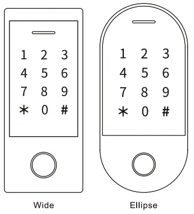
User Manual
INTRODUCTION
The device is a single door multifunction standalone access controller or a Wiegand output reader. It uses Atmel MCU assuring stable performance. The operation is very user-friendly, and low-power circuit makes it long service life.
The device supports 1,000 users (988 common users + 2 panic users + 10 visitor users), all user data can be transferred from one to another (except fingerprint users). It supports multi access modes in card access, PIN access, fingerprint access, card + PIN access, or multi cards /PINs/ fingerprints access. It has extra features including block enrollment, interlock, Wiegand input & output interface…etc.
Two Versions Optional: T
he device with Bluetooth function is optional
The device with big user capacity is optional
Features
> Capacitive fingerprint sensor, Touch key
> Metal case, anti-vandal
> Waterproof, conforms to IP66
> One relay, 1,000 users (988 common + 2 panic + 10 visitor)
> PIN length: 4-6 digits > EM card, Mifare Card optional
> EM card version: Wiegand 26-44 bits input & output Mifare card version: Wiegand 26-44bits, 56bits, 58bits input & output
> Can be used as Wiegand reader with LED & buzzer output
> Card block enrollment
> Tricolor LED status display
> Integrated alarm & buzzer output
> Pulse mode, Toggle mode
> User data can be transferred (except fingerprint users)
> 2 devices can be interlocked for 2 doors
> Built-in light dependent resistor (LDR) for anti tamper
> Backlit keypad, can set automatic OFF after 20 seconds
Specifications
| User Capacity Common User Panic User Visitor User | 1000 988 (100 Fingerprint + 888 Card/PIN Users) 2 10 |
| Operating Voltage Working Current Idle Current | 12∼28V AC/DC <150mA <60mA |
| Proximity Card Reader Radio Technology Read Range | EM orMifare 125KHz/ 13 56MHz 2-6cm |
| PIN Length | 4-6 digits |
| Wiring Connections | Relay Output, Exit Button, Alarm, Door Contact, Wiegand Input, Wiegand Output |
| Relay Adjustable Relay Output Time Lock Output Load | One (NO, NC, Common) 0-99 Seconds (5 seconds default) 2 Amp Maximum |
| Wiegand Interface PIN Output | EM card version: Wiegand 26-44 bits nput & output (Factory Default: Wiegand 26bits) Mifare card version: Wiegand 26-44bits, 56bits, 58bits input & output Factory Default: Wiegand 34bits) 4 bits, 8 bits(ASCII), 10 digits Virtual Number Factory Default: 4 bits) |
| Environment Operating Temperature Operating Humidity | Meets IP66 -30C-60C (-22F 140E) 0%RH-98%RH |
| Physical Colour Dimensions Unit Weight Shipping Weight | Zinc-Alloy Silver & Black L145 xW68 x D25 (mm) Wide L149W70 D25 (mm) Ellipse 500g (Wide) 455g(Ellipse) 615g(Wide) 565g(Ellipse) |
Carton Inventory
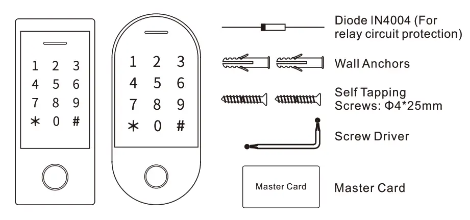
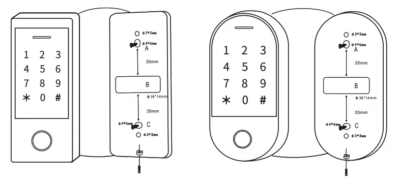
INSTALLATION
- Remove the back cover from the unit
- Drill 2 holes(A,C) on the wall for the screws and one hole for the cable
- Knock the supplied rubber bungs to the screw holes(A,C)
- Fi the back cover firmly on the wall with 4 flat head screws
- Thread the cable through the cable hole(B)
- Attach the unit to the back cover
Wiring
| Wire Color | Function | Notes |
| Basic Standalone Wiring | ||
| Red | AC&DC | 12-28V AC/DC Regulated Power Input |
| Black | AC&DC | 12-28V AC/DC Regulated Power Input |
| Pink | GND | Negative Pole |
| Blue | Relay NO | Normally Open Relay Output (install diode provided) |
| Purple | Relay Common | Common Connection for Relay Output |
| Orange | Relay NC | Normally Closed Relay Output (Install diode provided) |
| Yellow | OPEN | Request to Exit(REX) Input |
| Pass-Through Wiring (Wiegand Reader or Controller) | ||
| Green | Data 0 | Wiegand Output (Pass-through) Data 0 |
| White | Data 1 | Wiegand Output (Pass-through) Data 1 |
| Advanced Input and Output Features | ||
| Grey | Alarm Output | Negative contact for Alarm |
| Brown | Contact Input | Door/Gate Contact Input (Normally Closed) |
Sound and Light Indication
| Operation Status | LED | Buzzer |
| Stand by | Red light bright | — |
| Enter into programming mode | Red light shines | One beep |
| In the programming mode | Orange light bright | One beep |
| Operation error | — | Three beeps |
| Exit from the Programming mode | Red light bright | One beep |
| Open lock | Green light bright | One beep |
| Alarm | Red light Shines quickly | Beeps |
Basic Configure – – – ————
Enter and Exit Program Mode
| Programming Step | Keystroke Combination |
| Enter Program Mode | * (Master Code) # (Factory default is 123456) |
| Exit Program Mode | * |
Set Master Code
| Programming Step | Keystroke Combination |
| 1.Enter Program Mode | * (Master Code) # |
| 2.Update Master Code | 0 (New Master Code) # (Repeat New Master Code) # (Master code is any 6 digits) |
| 3.Exit Program Mode | * |
Set the Working Mode
Notes: The device has 3 working modes: Standalone Mode, Controller Mode, Wiegand Reader Mode, choose the mode you use. (Factory default is Standalone Mode / Controller Mode)
| Programming Step | Keystroke Combination |
| 1.Enter Program Mode | * (Master Code) # |
| 2.Standalone/Controller Mode OR 2. Wiegand Reader Mode | 7 7 # (Factory default) 7 8 # |
| 3.Exit | * |
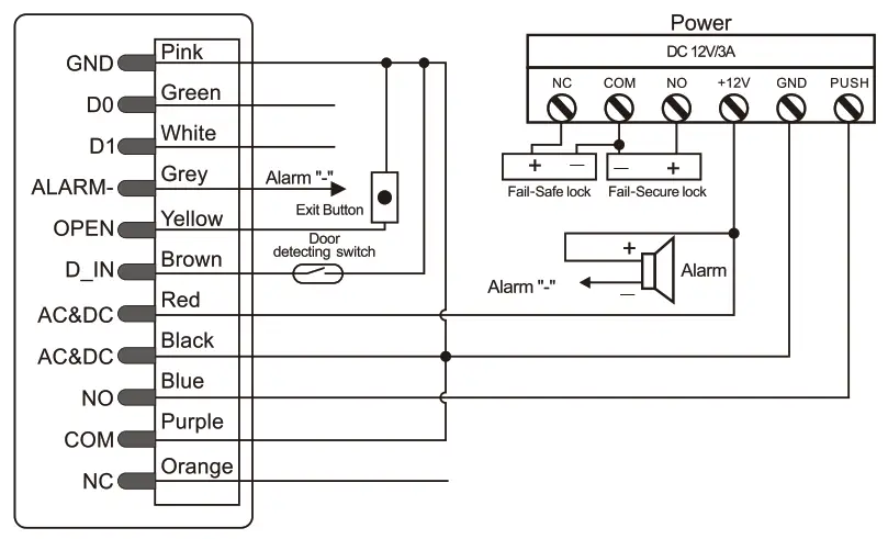
STANDALONE MODE
The device can work as Standalone Access Control for single door.
(Factory default mode)– 7 7#
Connection Diagram
Common Power Supply
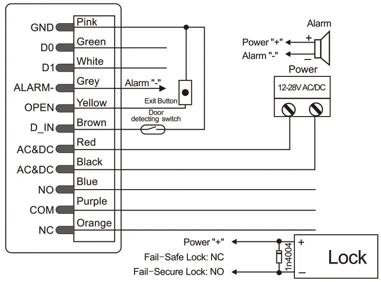
Attention:
Install a 1N4004 or equivalent diode is needed when use a common power supply, or the keypad might be damaged. (1 N4004 is included in the packing)
Access Control Power Supply
Programming
Programming will be vary depending on access configuration. Follow the instructions according to your access configuration.
Notes:
> User ID number: Assign a user ID to the access fingerprint/ card/ PIN in order to track it
The Common User ID:
– Fingerprint user ID 0 – 98
– PIN/ Card user ID. 100 – 987
Master Fingerprint User ID: 99
Panic User ID·988-989
Visitor User ID 990-999
IMPORTANT: User IDs do not have to be proceeded with any leading zeros.
Recording of User ID is cntical. Mochfications to the user require the User ID be available.
> Proximity Card:
Proximity Card. 125KHz EM card or 13.56MHz Mifare card
> PIN: Can be any 4-6 digits except 8888 which is reserved.
Add Common Users
(Fingerprint user ID: 0 – 98, PIN/ Card user ID: 100 – 987; PIN length: 4-6digits except 8888)
| Programming Step | Keystroke Combination |
| 1.Enter Program Mode | * (Master Code) # |
| Add Fingerprint User | |
| 2.Using Auto ID (Allows the device to assign Fingerprint to next available User ID number) OR 2. Select Specified ID (Allows Master to define a specific User ID to associate the fingerprint to) | 1 (Fingerprint) (Repeat Fingerprint) (Repeat Fingerprint again) Fingerprints can be added continuously. 1 (User ID) # (Fingerprint) (Repeat Fingerprint) (Repeat Fingerprint again) Fingerprints can be added continuously. |
| Add Card User | |
| 2. Using Auto ID (Allows the device to assign Card to next available User ID number) OR 2. Select Specific ID (Allows Master to define a specific User ID to associate the card to) OR 2. Add Card: Block Enrollment (Allows Masterto add up to 888 cards to the Reader in a single step) Takes 2 minutes to program. | 1 (Read Card)! (Input 8/10/17 Digits Card Number) # The cards can be added continuously. 1 (User ID) # (Read Card)! (Input 8/10/17Digits Card Number)# 1 ( User ID) # (Card Quantity) # (The First Card 8/10/17Digits Number)# Cards’ number must be consecutive; Card quantity = number of cards to be enrolled |
| Add PIN User | |
| 2. Using Auto ID (Allows the device to assign PIN to next available User ID number) OR 2.Select Specific ID (Allows manager to define a specific User ID to associate the PIN to) | 1 (PIN) )# The PINs can be added continuously 1 (User ID) # (PIN ) # |
| 3.Exit | * |
Tips for PIN Security (Only valid for 6 digits PIN):
For higher security we allow you to hide your correct PIN with other numbers up to a max of 10 digits
Example PIN. 123434
You could use (123434) 0r(123434)
( can be any numbers from 0-9)
Add Master Fingerprint (By Specified ID: 99)
| Programming Step | Keystroke Combination |
| 1. Enter Program Mode | * (Master Code) # |
| 1. Add Master Fingerprint | 1 (99) # (Fingerprint) (Repeat Fingerprint) (Repeat Fingerprint again) |
| 3. Exit | * |
Add Panic Users (Valid for Card/ PIN Users)
(User ID number is 988, 989; PIN length: 4-6 digits except 8888)
| Programming Step | Keystroke Combination |
| 1.Enter Program Mode | * (Master Code) # |
| 2.Add Card OR 2. Add PIN | 1 (User ID) # (Read Card I Input 8/10 /17 Digits Card number)# 1 (User ID) # (PIN) )# |
| 3.Exit | * |
Add Visitor Users (Valid for Card/ PIN Users)
(User ID number is 990-999; PIN length: 4-6 digits except 8888)
There are 10 groups Visitor PIN/card available, the users can be specified up to 10 times of usage, after a certain number of times, i.e. 5times, the PIN/card become invalid automatically.
| Programming Step | Keystroke Combination |
| 1.Enter Program Mode | *(Master Code) # |
| 2.Add Card OR 2. Add PIN | 1 (User ID) # (0-9) # (Read Card)! (Input 8/10/17 Digits Card Number) # 1 (User ID) # (0-9) # (PIN) # (0-9 means times of usage, 0=10 times) |
| 3.Exit | * |
Change PIN Users(PIN length: 4-6 digits except 8888)
| Programming Step | Keystroke Combination |
| Note: Below Is done outside programming mode, users can undertake this themselves | |
| Change PIN | * (User ID) # (Old PIN) # (New PIN) # (Repeat New PIN) # |
| Change PIN of Card + PIN access mode (There will auto allocate PIN (8888) to cards when adding) | *(Read Card) (Old PIN) # (New PIN) # (Repeat New PIN) # |
| Programming Step | Keystroke Combination |
| 1. Enter Program Mode | * (Master Code) # |
| 2. Delete User- By Fingerprint/ Card/ PIN OR 2. Delete User – By ID number OR 2. Delete User – By Card number OR 2. Delete ALL Users | 2 (Input Fingerprint)/ (Read Card)/ (Input PIN) # The users can be deleted continuously. 2 (User ID )# 2 (input 8/10/17 Digits Card Number) # 2 (Master Code)# |
| 3. Exit | * |
Set Relay Configuration
The relay configuration sets the behaviour of the output relay on activation.
| Programming Step | Keystroke Combination |
| 1. Enter Program Mode | *(Master Code) # |
| 2. Pulse Mode OR 2. Toggle Mode | 3 (1–99)# (factory default) The relay time is 1-99 seconds. (Default is 5 seconds) 3 0 # Sets the relay to ON/OFF Toggle mode |
| 3. Exit | * |
Set Access Mode
For Multi user access mode, the interval time of reading can not exceed 5 seconds, or else, the device will exit to standby automatically.
| Programming Step | Keystroke Combination |
| 1. Enter Program Mode | *(Master Code) # |
| 2 Fingerprint Access OR 2 Card Access OR 2 PIN Access OR 2 Card+ PIN Access | 4 0# 4 1 # 4 2# 4 3# |
| Simplified Instruction | |
| Function Description | Operation |
| Enter the Programming Mode | * – Master Code – # then you can do the programming (123456 is the factory default master code) |
| Change the Master Code | 0 – New Code – # – Repeat the New Code – # (code: 6 digits) |
| Add Card User | 1 – Read Card – # (can add cards continuously) |
| Add Fingerprint User | 1-Fingerprint- Repeat Fingerprint-Repeat Fingerprint Again- # |
| Add PIN User | 1 -PIN -# (The PIN is any 4-6 digits except 8888 which is reserved ) |
| Delete User | 2- Fingerprint- # 2-Read Card- # 2-PIN-# |
| Exit from the Programming Mode | * |
| How to release the door | |
| Fingerprint User | Input Fingerprint |
| Card User | Read Card |
| PIN User | Input PIN # |
| 2 Multi User Access OR 2 Fingerprint or Card or PIN Access | 4 3 (2-9) # (Only after 2-9 valid users, the door be opened) 4 4 # (factory default) |
| 3. Exit | * |
Set Strike-out Alarm
The strike-out alarm will engage after 10 failed entry attempts (Factory is OFF).
It can be set to deny access for 10 minutes after engaging or disengage only after entering a valid Finerprint/ card/ PIN or Master code/ fingerprint/ card.
| Programming Step | Keystroke Combination |
| 1.Enter Program Mode | * (Master Code) # |
| 2.Strike-Out OFF OR 2. Strike-Out ON OR 2. Strike-Out ON (Alarm) Set Alarm Time | 6 0 # (factory default) 61 # Access will be denied for 10minutes (Exit button is still workable) 6 2# 5 (0 – 3) # (factory default Is 1 minute) Enter Master Code # or Master Fingerprint / Card or valid user fingerprint / card / PIN to silence |
| 3. Exit | * |
Set Door Open Detection
Door Open Too Long (DOTL) Detection
When use with an optional magnetic contact or built-in magnetic contact of the lock, if the door is opened normally, but not dosed after 1 minute, the inside buzzer will beep automatically to remind people to dose the door. The beep can be stopped by closing the door, master users or valid users, or else, it will continue to beep the same time with the alarm time set.
Door Forced Open Detection
When use with an optional magnetic contact or built-in magnetic contact of the lock, if the door is opened by force, the inside buzzer and external alarm (if there is) will both operate, they can be stopped by master users or valid users, or else, it will continue to sound the same time with the alarm time set.
| Programming Step | Keystroke Combination |
| 1. Enter Program Mode | * (Master Code)# |
| 2. Disable Door Open Detection OR 2. Enable Door Open Detection Set Alarm Time | 6 3# (factory default) 6 4# 5 (0 — 3) # (factory default is 1 minute) |
| 3. Exit | * |
The function of Set Alarm Time also apply for anti-tamper alarm
Set Audible and Visual Response
| Programming Step | Keystroke Combination |
| 1. Enter Program Mode | * (Master Code)# |
| 2 Disable Sound Enable Sound OR 2. LED Always OFF LED Always ON OR 2. Keypad Backlit Always OFF Keypad Backlit Always ON Keypad Backlit Automatic OFF | 7 0# 7 1# (factory default) 7 2# 7 3# (factory default) 7 4 # 7 5# 7 6 # (factory default) Automatic OFF after 20 seconds, it will go ON by pressing any key (this key isn’t taken into consideration) |
| 3. Exit | * |
Master Fingerprint/ Card Usage
| Using Master Fingerprint/ Card to add and delete users | |
| Add Fingerprint/ Card/ PIN Users | 1. Input (Master Fingerprint I Card) 2. Input (Fingerprint three times) or (Card) or (PIN#) Repeat step 2 for additional users 3. Input (Master Fingerprint/ Card) again |
| Delete Fingerpnnt/ Card/ PIN Users | 1. Input (Master Fingerprint/ Card Twice within 5s) 2. Input (Fingerprint) or (Card) or (PIN #) Repeat step 2 for additional users 3. Input (Master Fingerprint/ Card) again |
Users Operation & Resetto Factory Default
>Open the door Read valid user fingerprint or user card or input valid user PIN#
> Remove Alarm: Enter Master Code# or Master Fingerprint/ Card or valid user fingerprint/ card / PIN
> To reset to factory default &Add Master Card: Power off, press the Exit
Button, hold it and power on, there will be two beeps, then release the exit button, the LED light turns into yellow, then read any 125KHz EM card/ 13.56MHz Mifare card, the LED will turn into red, means reset to factory default successfully Of the card reading, it is the Master Card.
Remarks:
- If no Master Card added, must press the Exit Button for at least 5 seconds before release.(this will make the previous registered Master Card invalid)
- Reset to factory default, the user’s information is still retained.
CONTROLLER MODE
The device can work as Controller, connected with the external Wiegand reader.
(Factory default mode)— 7 7#
Connection Diagram
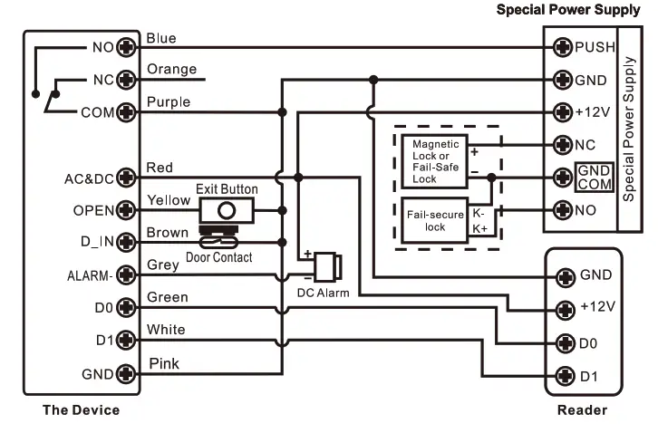
Attention: Install a 1N4004 or equivalent diode is needed when use a common power supply, or the reader might be damaged. (1 N4004 is included in the packing)
Set Wiegand Input Formats
Please set the Wiegand input formats according to the Wiegand output format of the external Reader.
| Programming Step | Keystroke Combination |
| 1.Enter Program Mode | * (Master Code) # |
| 2.Wiegand Input Bit | EM Card Version: 8 (26— 44) # (factory default is 26bits) Mifare Card Version: 8 (26— 44, 56, 58) # (factory default is 34bits) |
| 3.Disable Parity Bit Enable Parity Bit | 8 0 # 81 # (factory default) |
| 4.Exit | * |
Note: For connecting Wiegand readers with 32. 40. 56 bits output, need disable parity bits.
Programming
> Basic Programming is the same as Standalone Mode
> There are some exceptions for your attention:
The device Connected with External Card Reader
– If EM/Mifare card reader: users can be added/deleted on either the device or external reader.
-If HID card reader: users can only be added/deleted on external reader.
The device Connected with Fingerprint Reader
For example:
Connect SF1 as the fingerprint reader to the device.
Step 1:Add the Fingerprint (A) on SF1 (Please refer to SF1 manual)
Step 2: Add the same Fingerprint(A) on the device:
| 1 | Enter Program Mode: + (Master Code) # |
| 1 (Press Fingerprint A once on SF1) # (ID auto allocated) 2 OR 1 (User ID)# (Press Fingerprint Aon SF1) # (Select specific ID) 2 | |
| 3 | Exit: |
The device Connected with Keypad Reader
The keypad reader can be 4 Bits, 8 Bits (ASCII), or 10 Bits output format.
Choose the below operation according to the PIN output format of your reader.
| Programming Step | Keystroke Combination |
| 1. Enter Program Mode | * (Master Code)# |
| 2. PIN input bits | 8 (4 or 8 or 10) # (factory default is 4 bits |
| 3. Exit | * |
Remarks: 4 means 4 bits, 8 means 8 bits, 10 means 10 digits virtual number.
> Add PIN Users:
To add PIN users, after enter into programming mode on the device, PIN(s) can be input/ added on either the device or the external Keypad Reader.
> Delete PIN Users: the same way as add users.
WIEGAND READER MODE
The device can work as Standard Wiegand Reader, connected to the third party
Controller –7 8 #
Connection Diagram
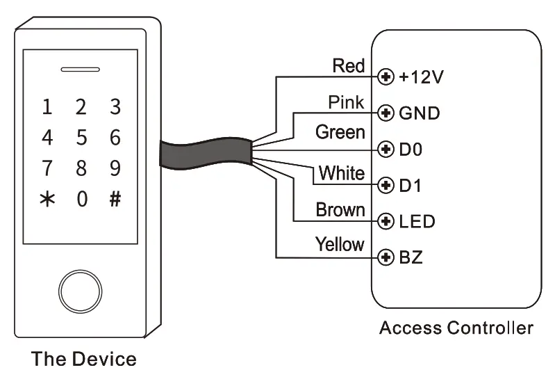
Notes:
> When set into Wiegand Reader mode, nearly all settings in Controller Mode will become invalid, and Brown & Yellow wires will be redefined as below:
– Brown wire: Green LED light control
– Yellow wire: Buzzer control
> If you need to connect Brown/Yellow wires:
When the input voltage for LED is low, the LED will tum into Green; and when the input voltage for Buzzer is low, it will sound.
Set Wiegand Output Formats
Please set the Wiegand output formats of Reader according to the Wiegand input formats of the Controller.
| Programming Step | Keystroke Combination |
| 1.Enter Program Mode | * (Master Code) # |
| 2.Wiegand output bits PIN output bits | EM Card Version: 8 (26— 44) # (factory default is 26bits) Mifare Card Version: 8 (26— 44, 56, 58) # (factory default is 34 bits) 8 (4 or 8 or 10) # (factory default is 4 bits) |
| 3 Disable Parity Bit Enable Parity Bit | 8 0 # 81 # (factory default) |
| 4. Exit |
Note: For connecting Wiegand controller with 32. 40. 56 bits input, need disable parity bits.
ADVANCED APPLICATION
user Information Transfer (Valid for Card I PIN Users)
The device supports the User Information Transfer function, and the enrolled user (cards, PINs) can be transferred from one (let’s name it Master Unit) to another (let’s name it Accept Unit).
Connection Diagram:
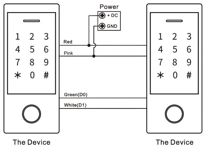
Remarks:
> The Master units and Accept units must be same series devices.
> The Master Code of the Master Unit and the Accept Unit must be set to the same.
> Program the transfer operation on Master Unit only.
> If the Accept Unit is already with the users enrolled, it will be covered after transfemng.
> For full 900 users enrolled, the transfer takes about 30 seconds.
Set Transferring on Master Unit:
| Programming Step | Keystroke Combination |
| 1. Enter the programming mode | * (Master Code)# |
| 2. Set transferring | 98# |
| Within 30 seconds, Green LED shines, after one beep, the LED will turn into Red, which means the users’ information has been transferred successfully. | |
| 3. Exit | * |
Interlock
The device supports the Interlock Function. It is of two Devices for two doors, and mainly used for banks, prisons, and other places where a higher level security is required.
Connection Diagram:
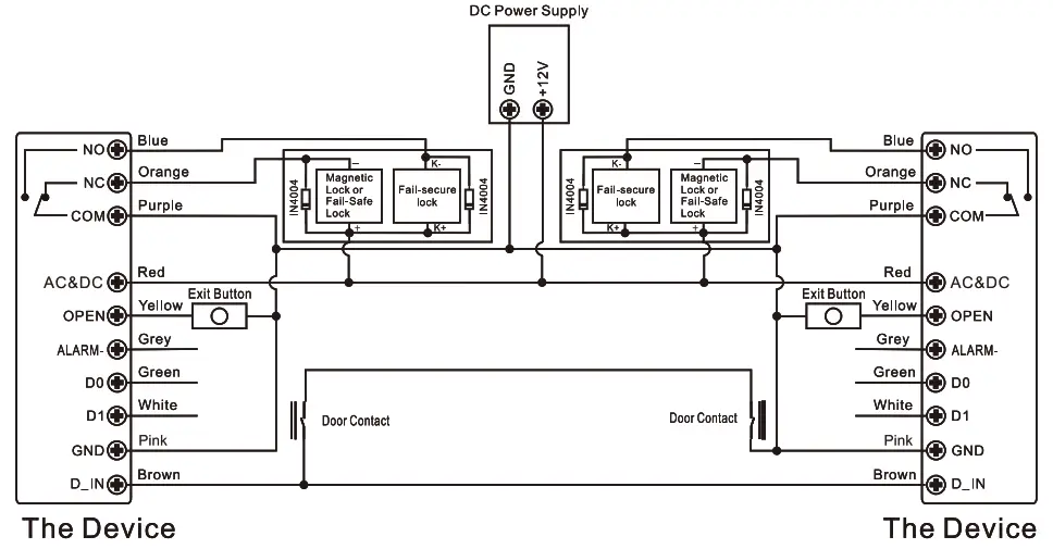
Remarks: The Door Contact must be installed and connected as the diagram.
Let’s name the two Devices as “A “and “B” for two doors “1” and “2” Step 1:
Enroll the users on Device A, then transfer the users’ information to Device B by “User Information Transfer” funciton.
Step 2:
Set both of the two Devices (A and B) to Interlock function
| Programming Step | Keystroke Combination |
| 1. Enter Program Mode | * (Master Code)# |
| 2. Disable Interlock OR 2. Enable Interlock | 90# (factory default) 91# |
| 3. Exit | * |
If enable interlock, when and only door 2 is closed, the user can read the valid fingerprint/card or input PIN on Reader A, door 1 will open; then when and only door 1 closed,read valid fingerprint/card or input PIN on Reader B, door 2 will open.
WiFi Access Control 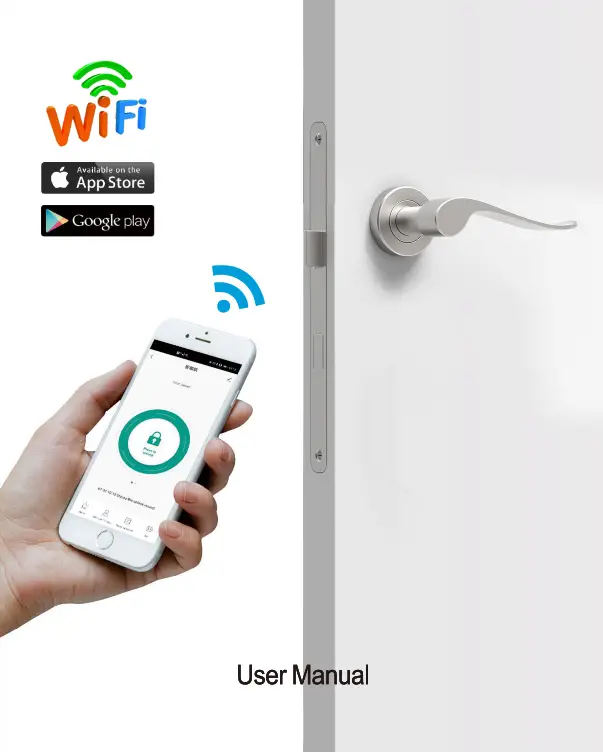
Introduction
This device is a WiFi based Touch Key Access Controller & RFID Reader People can install the mobile APP (TuyaSmart or Smartlife) to easily access the door with their smartphone. The App supports 500 mobile users, and can manage 1000 users (Fingerprint/PIN /Card) maximum by the APP
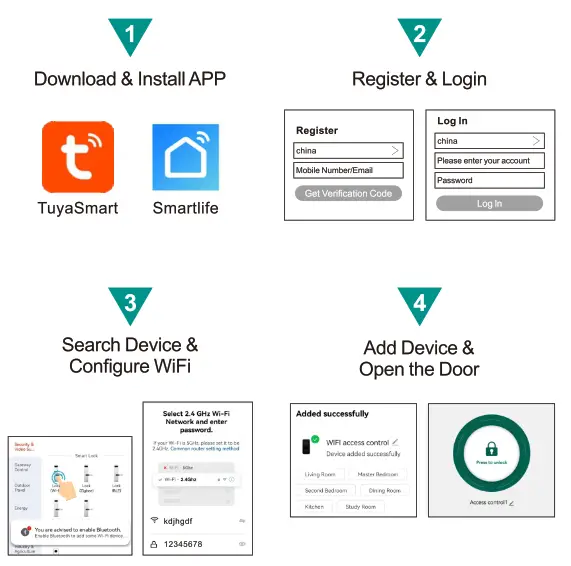
APP Operation
Here are just a few steps to get you started.
1)Free App Downloading
Search TuyaSmart or Smartlife on Google Play or APP Store![]()
2)Make sure WiFi works on your mobile phone.
Register & Login
(Make sure the registered email is legal and valid, so that you can recover your password once forgotten. Mobile Number is for China Mobile ONLY) 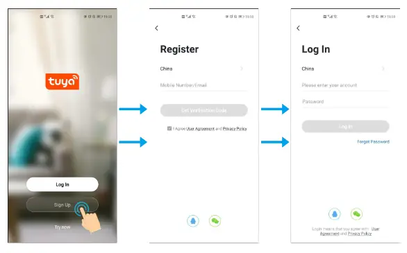
You will get a verification code in your mail box
Add Device
You can add device by clicking ‘Add Device’or clicking ‘+’on the top.
(It is suggested to turn on the Bluetooth, it’s easier to find the device and faster to add device ) 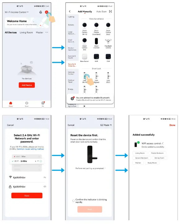
Note: To better manage the devices and family members, you will need to create a HOME before you begin to manage this device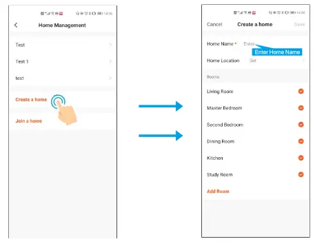 Attention: When the user first Open the lock through APP, APP will ask you to Switch on ‘remote unlock’ first
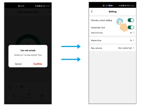
Member Management
Note The first to add the device is the Home Owner (Super Master)
| Authority | Home Owner (Super Master) | Administrator | Ordinary member |
| Open the door | √ | √ | √ |
| Member Management | √ | √ | X |
| User Management | √ | √ | X |
| Set Users as Admin | √ | X | X |
| View All Records | √ | √ | X |
| Set Relay Time | √ | √ | X |
User Management
4.1 Add Members
(Note. The members that you shared to must register the account first.)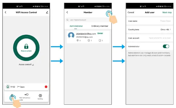
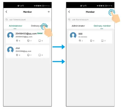
Remark: When adding members, the Owner (Super Master) can decide to add the user as Admin or Ordinary member
4.2 Manage Members
Owner(Super Master) can decide effective time (Permanent or Limited) of the members 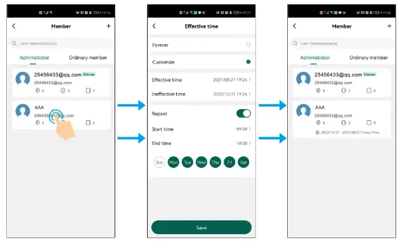 (Same operation for Ordinary member)
4.3 Delete Members
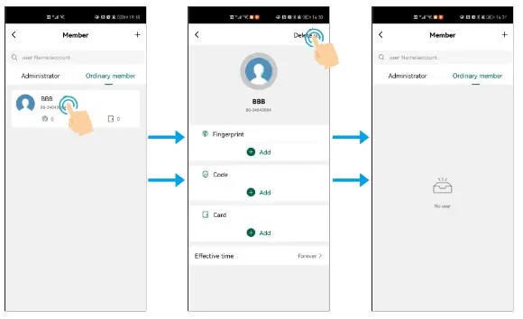
4.4Add Users (Fingerprint/ PIN/ Card Users)
The APp supports to Add/Delete Fingerprint/ PIN / Card users 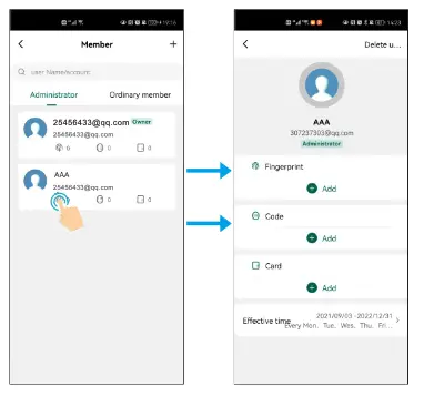
Simplified Instruction
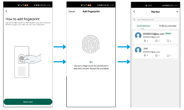
For adding PIN & Card users, same operation as adding Fingerprint user
4.5 Delete Users (Fingerprint/ PIN/ Card Users) 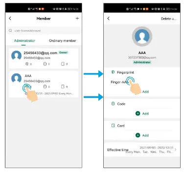
For deleting PIN & Card users, same operation as deleting Fingerprint user
Temporary Code
The temporary code can be shared by SNS tools (Whatsapp, Skype, Wechat. ) or email to the guest/users.
For Temporary Code. there are two types of it
Cyclicity For example, valid at 9:00am-6:00pm every Monday-Friday during
August–October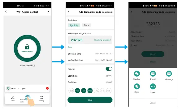
Once: One-time code can be valid in 6 hours and can be used only for once 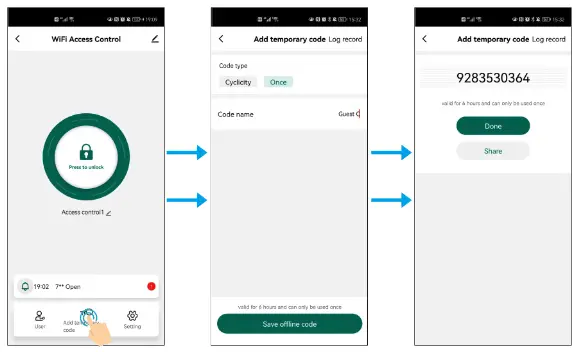
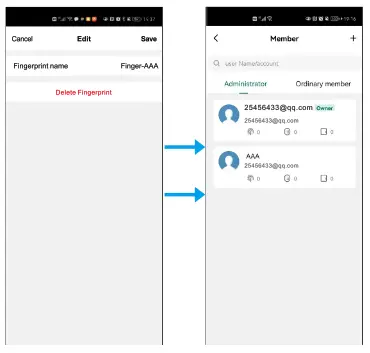
5.1 Edit Temporary Code
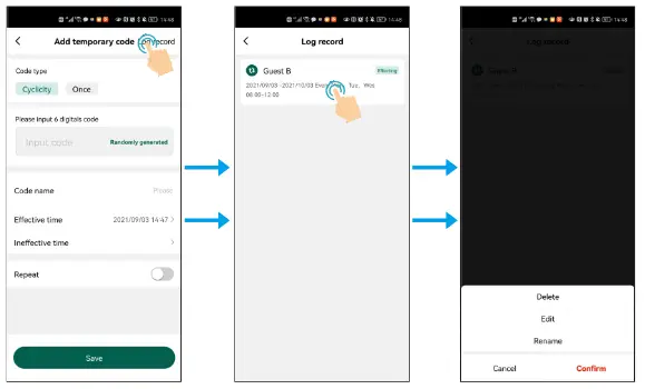 The temporary code can be also deleted, editted or renamed in the valid period
Setting
6.1 Remote unlock setting
Default is off. When added the device first time, it will ask to turn on. Once turn off. all the mobile users will not be able to access the lock by APP
6.2 Automatick Lock
Default is on.
Automatic Lock on: Pulse Mode
Automatic Lock off. Latch Mode
6.3 Auto lock time
Default is 5 seconds. It can be set from 0-100 seconds.
6.4 Alarm lime
Default is 1 minutes. It can be set from 1-3 minutes.
6.5 Key Volume
It can set Key Volume Mute, Low, Middle and High. 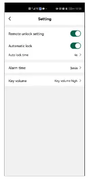
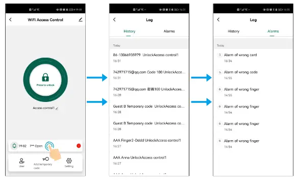
Log ( Including Open History and Alarms)
Remove Device & Reset Bluetooth Binding
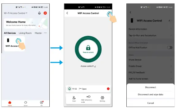
Note:
Disconnect is just removing the device from the App The users (card /fingeprirnt /code) are still retained (If Super Master Disconneted, all other memebers will have no access to the device)
Disconnect and wipe data is unbinding the device and reset Bluetooth.
(Means this device can be connected by other new users)
Method 2 to reset the WiFi
(Master Code) #-Default Master Code is 123456
9 (Master Code)#
(To change the Master Code. please refer to another user manual)
ATTENTION:
There are 3features (Programming on the Device) that are NOT supported by the WiFi version
- Change PIN’
- Card+ PIN’ Access Mode
- Tips for PIN Security’ —- It supports to hide your correct PIN with other numbers up to a max of 9 digits only
![]()


