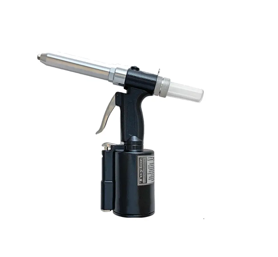
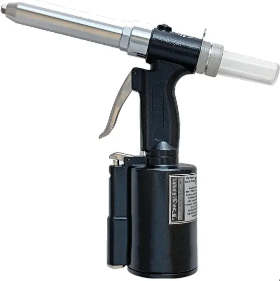
Taylor Pneumatic Tool Company T-7891A Heavy Duty Extended Nose Riveter
OILING INSTRUCTIONS
Oiling Procedure
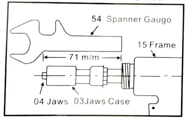
ADJUSTING LENGTH
USE 90 PSI MAXIMUM
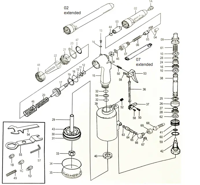
| Ref.# | Part # | Description | Qty. |
| 1A | 789101AN | 3/16” Nose Piece | 1 |
| 1B | 789101BN | 5/32” Nose Piece | 1 |
| 1C | 789101CN | 1/8” Nose Piece | 1 |
| 1D | 789101DN | 3/32” Nose Piece | 1 |
| 2 | 789102L | Frame Head – extended | 1 |
| 2 | 789102N | Frame Headd – short | 1 |
| 3 | 789103N | Jaws Case | 1 |
| 4 | 789104N | Jaws | 2 |
| 5 | 789105N | Jaw Pusher | 1 |
| 6 | 789106N | Jaw Case Spring | 1 |
| 7 | 789107L | Jaw Case Back-extended | 1 |
| 8 | 789108N | Case Lock Nut | 1 |
| 9 | 789109N | Valve Pusher | 1 |
| 10 | 789110N | “E” Ring | 2 |
| 11 | 789111N | Back Up Ring | 1 |
| 12 | 789112N | “O” Ring | 2 |
| 13 | 789113N | Plug | 1 |
| 14 | 789114N | Packing | 1 |
| 15 | 789115N | Frame | 1 |
| 16 | 789116N | Valve Ring Seal | 1 |
| 17 | 789117N | Oil Piston | 1 |
| 18 | 789118N | “O” Ring | 1 |
| 19 | 789119N | Back Up Ring | 1 |
| 20 | 789120N | Return Spring | 1 |
| 21 | 789121N | Frame Cap | 1 |
| 22 | 789122N | Catcher | 1 |
| 23 | 789123N | Hanging Clip | 1 |
| 24 | 789124N | Air Trigger Ring | 1 |
| 25 | 789125N | “O” Ring | 1 |
| 26 | 789126N | Valve Seat | 1 |
| 27 | 789127N | “O” Ring | 1 |
| 28 | 789128N | Ring Seal Washer | 1 |
| 29 | 789129N | Air Piston Rod | 1 |
| 30 | 789130N | “O” Ring | 1 |
| 31 | 789131N | Air Piston | 1 |
| 32 | 789132N | “O” Ring | 2 |
| 33 | 789133N | Lock Nut | 1 |
| 34 | 789134N | “O” Ring | 1 |
| 35 | 789135N | Cylinder Cap | 1 |
| 36 | 789136N | Trigger Rod | 1 |
| 37 | 789137N | Trigger Lever | 1 |
| 38 | 789138N | Valve Pusher | 1 |
| 39 | 789139N | Air Cylinder | 1 |
| 40 | 789140N | Frame Lock Nut | 1 |
| 41 | 789141N | Nut | 1 |
| 42 | 789142N | Joint Nut | 1 |
| 43 | 789143N | Rubber Cushion | 1 |
| 44 | 789144N | Jaw Case “O” Ring | 1 |
| 45 | 789145N | Washer Ring | 1 |
| 46 | 789146N | Return Spring | 1 |
| 47 | 789147N | Frame Cap O Ring | 1 |
| 48 | 789148N | Catcher Nut | 1 |
| 49 | 789149N | M8 Bolt Plug | 1 |
| 50 | 789150N | Pin | 1 |
| 51 | 789151N | Lever Pin | 1 |
| 52 | 789152N | Pin Nut | 1 |
| 53 | 789153N | Trigger | 1 |
| 54 | 789154N | Wrench | 1 |
| 55 | 789155N | Wrench | 1 |
| 56 | 789156N | Back Up Ring | 1 |
| 57 | 789157N | Hex Wrench | 1 |
| 58 | 789158N | Trigger Pin | 2 |
| 59 | 789159N | “O” Ring | 1 |
| 60 | 789160N | “O” Ring | 1 |
| 61 | 789161N | Spring | 1 |
| 62 | 789162N | “E” Ring | 1 |
| 63 | 789163N | Throttle Valve Assembly | 1 |
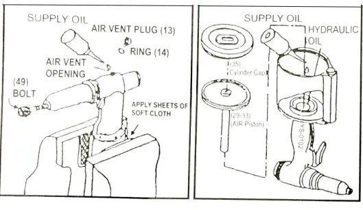
OPERATING INSTRUCTIONS FOR THE T-7891A RIVET TOOL
- Maintain fluid levels – Use 30 wt. oil. There are two methods of adding oil to the T-7891A.
A. PREFERREDWAY: Mount tool in vice with bottom cap # 35 up. Remove #35 with wrench #55. Remove entire piston (part #29, 30, 31, 32, 33, 34) as an assembly, by grasping #33 with a pair of pliers and pulling straight up. After the piston is removed fill with 30 weight non detergent oil to top of #40 nut (no oil should be in the #39 cylinder). Replace #35 Cap, and remove tool from the vice. With the tool in the upright position, remove #13 screw and excess oil will be vented. Wipe away excess oil, and replace #13. The total amount of oil should be 1/2 tablespoons.
B. Mount the T-7891A in a vice in the upright position, using cardboard or cloth to prevent marring the finish. Remove #13 oil fill screw. Remove #01A, B, C or D nosepiece. Screw in #49 bolt plug with #57 hex wrench to open the oil passage. Gradually add oil through the vent opening. Replace the fill screw #13. Remove #49 and replace with #01 nosepiece. Remove fill screw #13 to vent excess oil. (Too much oil in the system can cause a failure of the housing). A few drops of 30 wt oil or air tool oil through the air inlet every 10 to 15 minutes is recommended if no air line oiler is in place. - Adjusting the stroke – Remove #02 by using #55 wrench. For maximum stroke, loosen nut #08 and thread the nut all the way onto #17 piston. Then loosen #03 and #07 and thread them all the way to #08. Hold #08 with a wrench and tighten #3. For a shorter stroke, adjust #08 so that it is away from the shoulder of #17 by two or more threads, depending on how short you want the stroke to be.
- Always use the correct size nosepiece for the rivet you are using. It is a good idea to use a silicone oil such as WD 40 to lubricate the jaws #04 when pulling quantities of rivets, as there may be a build up of metal particles that could cause mandrels to stick in the jaws.
- Air pressure – The maximum pressure should be 90 PSI. A higher pressure could cause damage to your tool. Using the lowest pressure possible for your appplication will extend the life of your tool dramatically.
- As with all tools, make sure that all parts are tight from time to time, as vibration from use may loosen components.
- Mandrels – The T-7891A comes complete with the #22 mandrel catcher. Once a rivet has been popped, and the next rivet is mounted in the nosepiece, the last mandrel will slide into the #22. To remove mandrels, turn the tool upside down and they will fall out of the slot in #22, or remove #22 completely and empty.
505 N. Railroad Ave. 33435
P.O. Box 1117 33425 Boynton Beach, Florida
FOR WARRANTY INFORMATION & WARRANTY REGISTRATION VISIT
www.taylorpneumatic.com
1122 TPTC / all rights reserved / COPYRIGHT 2022 /final
561-732-1111
FAX 561-731-4412
Toll Free 800-805-8665