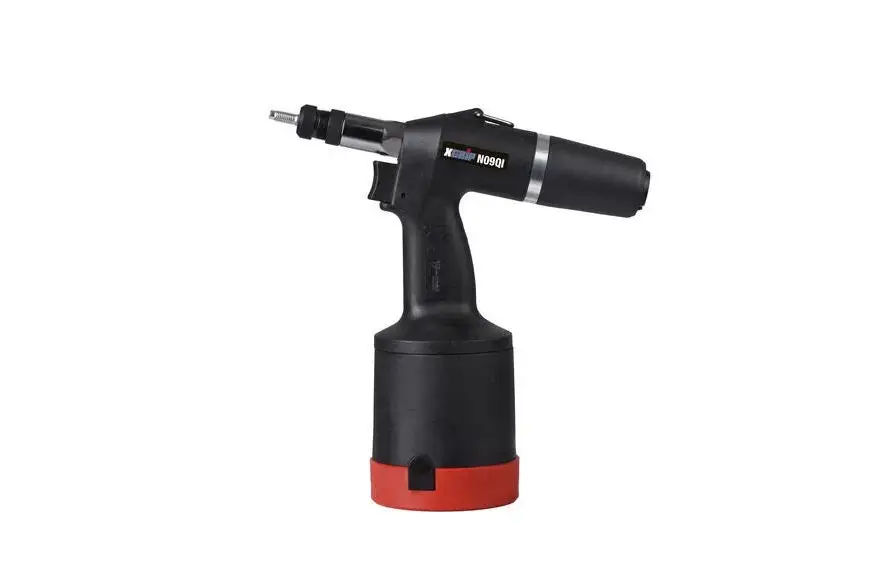
STANLEY XGRIP N09QI Hydro Pneumatic Powered Blind Rivet Nut Tool
Product Information
The XGRIP N09QI is a hydro-pneumatic tool used for riveting. It operates on compressed air and comes with a service kit (S-1008000). The tool has a stroke force adjustment and a manometer to indicate the pressure. The tool is made up of several parts, including mandrels, anvils, joint sleeve, front nozzle, O-rings, and hydraulic piston.
Product Usage Instructions
Before using the XGRIP N09QI tool, make sure it is disconnected from the compressed air. All threads on the tool are clockwise. When assembling or disassembling the tool, it should be gripped in a stand (see chapter 8) unless otherwise stated. Before assembling the tool, wash all disassembled parts in a degreasing solution and insufflate with compressed air. While assembling, lubricate the sealing (O-rings, pneumatic seals) and related opposite surfaces with oil MOGUL LV 2-3 unless stated otherwise.
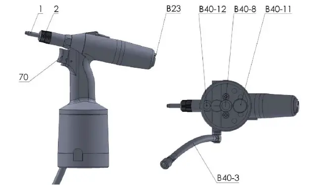
When using the tool, put a rivet on pos. 1 and press towards the riveting tool. The rivet will screw on, and the motor will turn right, outlet of CA through the outlets in pos. 23. The action is ready when the rivet is completely screwed on. Then, press pos. 70, and the rivet is riveted in. The rivet is deformed, and the movement ends when the set stroke force is reached.
To disassemble a rivet, press with hand pos. 23, and the rivet screws out. Motor turns left, outlet CA through the outlets in pos. 23. Release pos. 23, screwing out stops. Pos. 23 gets back to the initial position, motor turns off, air does not leak. Turn with stroke force adjustment according to arrow direction +/-.
The tool has a manometer that indicates the pressure. The indicator of the manometer moves when a rivet is put on pos. 1 and pressed towards the riveting tool. The motor turns right, outlet of CA through the outlets in pos. 23, and when the rivet is completely screwed on, the motor turns off.
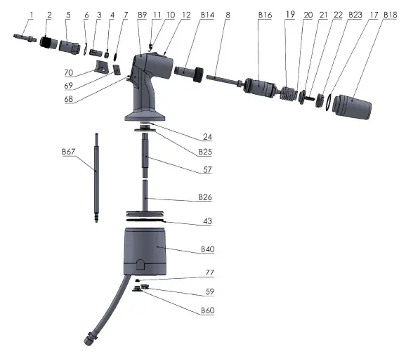
The XGRIP N09QI tool comes with a service kit (S-1008000) and a list of spare parts. Refer to the assembly drawing and informative list of spare parts when replacing or repairing any part of the tool.
©2022 STANLEY Black & Decker
All rights reserved.
The information provided may not be reproduced and/or made public in any way and through any means (electronically or mechanically) without prior explicit and written permission from STANLEY Engineered Fastening. The information provided is based on the data known at the moment of the introduction of this product. STANLEY Engineered Fastening pursues a policy of continuous product improvement and therefore the products may be subject to change. The information provided is applicable to the product as delivered by STANLEY Engineered Fastening. Therefore, STANLEY Engineered Fastening cannot be held liable for any damage resulting from deviations from the original specifications of the product.
The information available has been composed with the utmost care. However, STANLEY Engineered Fastening will not accept any liability with respect to any faults in the information nor for the consequences thereof. STANLEY Engineered Fastening will not accept any liability for damage resulting from activities carried out by third parties. The working names, trade names, registered trademarks, etc. used by STANLEY Engineered Fastening should not be considered as being free, pursuant to the legislation with respect to the protection of trademarks.
Abbreviations
CA – Compressed air
MP – Special tool (assembly jig)
General instructions
- 1. Riveting tool is always deconnected from the compressed air, unless otherwise stated.
2. All threads are clockwise.
3. Riveting tool is gripped in a stand (see chapter 8) while assembling and disassembling, unless otherwise stated.
4. Before assembling, wash the disassembled parts in degreasing solution and insufflate with compressed air, wipe with a cloth without hairs.
5. While assembling, lubricate the sealing (O-rings, pneumatic seals) and related opposite surfaces with oil MOGUL LV 2-3, unless stated otherwise.
Service kit
The part number for service kit is: S-1008000
Proper function of riveting tool
| Operator activity | Tool function |
| Connect the riveting tool to CA, if the tool is equiped with main valve, turn it on. Pos. 70 is on the front extreme position, not pressed | CA does not leak, motor does not rotate |
| Put a rivet on pos. 1 and press towards the riveting tool, the rivet screws on | Motor turns right, outlet of CA through the outlets in pos. 23 |
| The action is ready when the rivet is completely screwed on | Motor turns off, front of the rivet touches front of the pos. 2. CA does not leak |
| Press with hand pos. 23, the rivet screws out | Motor turns left, outlet CA through the outlets in pos. 23 |
| Release pos. 23, screwing out stops | Pos. 23 gets back to the initial position, motor turns off, air does not leak |
| Turn with stroke force adjustement according to arrow direction +/-. Further instructions are in the Operations manual | The indicator of the manometer moves |
| Put a rivet on pos. 1 and press towards the riveting tool, the rivet screws on | Motor turns right, outlet of CA through the outlets in pos. 23, when the rivet is completely screwed on the motor turns off |
| Press pos. 70, the rivet is riveted in | The rivet is deformed, the movement ends when the set stroke force is reached |
| Stop pressing pos. 70, the rivet completely screws out | CA outlets from the space pos. B40, pos. 1 gets back, the motor turns, outlet of CA through the outlets ins pos. 23, in the end motor stops itself, CA does not leak |
Assembly drawing of riveting tool
| Position | Part Number. | Description | Qty | |
| 1 | O900A00275 | Mandrel M3 | 1 | |
| 1 | O900A00276 | Mandrel M4 | 1 | |
| 1 | O900A00277 | Mandrel M5 | 1 | |
| 1 | O900A00278 | Mandrel M6 | 1 | |
| 1 | O900A00279 | Mandrel M8 | 1 | |
| 1 | O900A00280 | Mandrel M10 | 1 | |
| 1 | O900A00281 | Mandrel M12 | 1 | |
| 2 | O900A00282 | Anvil M3 complete | 1 | |
| 2 | O900A00283 | Anvil M4 complete | 1 | |
| 2 | O900A00284 | Anvil M5 complete | 1 | |
| 2 | O900A00285 | Anvil M6 complete | 1 | |
| 2 | O900A00286 | Anvil M8 complete | 1 | |
| 2 | O900A00287 | Anvil M10 complete | 1 | |
| 2 | O900A00288 | Anvil M12 complete | 1 | |
| 3 | D-08650400 | Joint sleeve | 1 | |
| 4 | O900P01201 | Contra-nut | 1 | |
| 5 | D-08650600 | Front nozzle | 1 | |
| 6 | O920064019 | O – ring 16/1,25 Sh 70 | 1 | |
| 7 | O920063006 | O – ring 14,3/2,4 Sh 70 | 1 | |
| 8 | O900P01202 | Tensile screw | 1 | |
| 9 | S-08651900 | Hydraulic body | 1 | |
| 10 | O900S00136 | O – ring 4/1,5 Sh 90 | 1 | |
| 11 | O920R50H12 | Screw M4x6 imbus DIN 912 | 1 | |
| 12 | O920R50H13 | Hanger | 1 | |
| 14 | S-08650900 | Hydraulic piston complete | 1 | |
| 1402 | N-2300007342283 | Lip seal 34x22x8,3 (red color) | 1 | |
| 1403 | O900S00155 | Guiding band 35 | 1 | |
| 16 | S-08655000 | Motor complete | 1 | |
| 17 | O900S00229 | O – ring 36/2 Sh 70 | 1 | |
| 18 | S-08652700 | Rear screwing complete | 1 | |
| 1801 | D-08652700 | Rear screwing | 1 | |
| 1802 | D-08652800 | Cover | 1 | |
| 19 | D-08651500 | Compression spring | 1 | |
| 20 | O920N10024 | Compression spring | 1 | |
| 21 | D-08655600 | Push button piston | 1 | |
| 22 | O900P01210 | Compression spring | 1 | |
| 23 | S-08655500 | Push button complete | 1 | |
| 2302 | N-3700000100400 | Filtr SB Fi 10×4 mm/E | 2 | |
| 24 | D-08653300 | Washer PP | 1 | |
| 25 | S-08653200 | Cover plate D12 complete | 1 | |
| 2501 | D-08653200 | Bottom | 1 | |
| 2502 | N-2040000000110 | Stepseal 11 | 1 | |
| 2503 | N-2103701310262 | O – ring 13,1/2,62 Sh 70 | 1 | |
| 2505 | O900S00215 | O – ring 18/2,2 VITON | 1 | |
| 26 | S-08653000 | Pneumatic plunger | 1 | |
| 2602 | O920R50H22 | Adjusting ring 14 | 3 | |
| 2603 | O900S00127 | O – ring 10/2 Sh 70 | 3 | |
| 40 | S-08650700 | Pneumatic cylinder complete | 1 | |
| 4001 | D-08650700 | Pneumatic cylinder | 1 | |
| 4002 | P-08604302 | Bottom ring – red color | 1 | |
| 4003 | S-08654201 | Aircoupling | 1 | |
| D-08654200 | Body of aircoupling | 1 | ||
| N-2103700910160 | O – ring 9,1/1,6 Sh 70 | 1 | ||
| O900A00317 | Air supply rot. part compl. | 1 | ||
| 4005 | O900S00110 | O – ring 17,17/1,78 Sh 70 | 2 | |
| 4006 | D-08600601 | Piston of stroke valve | 1 | |
| 4007 | N-2103701000220 | O – ring 10/2,2 Sh 70 | 1 | |
| 4008 | N-2104000700200 | O – ring 7/2 VITON | 1 | |
| 4009 | D-08600604 | Spring | 1 | |
| 4011 | N-8400000086504 | Sticker of regulation key | 1 | |
| 4012 | D-08600800 | Screw joint of pressure gauge | 1 | |
| 4013 | N-2103700975178 | O – ring 9,75/1,78 Sh 70 | 1 | |
| 4014 | O920N08045 | Pressure gauge | 1 | |
| 4015 | N-8400000086506 | Sticker of regulation scale | 1 | |
| 4016 | O920063014 | O – ring 7/1,2 Sh 70 | 1 | |
| 4017 | S-08653700 | Outlet regulation | 1 | |
| 43 | O920R50S39 | O – ring 82,14/3,53 Sh 70 | 1 | |
| 57 | O920R50S37 | Connecting screw | 2 | |
| 59 | O920063026 | Nut M6 DIN 6331 zinc. | 2 | |
| 60 | S-08654300 | Nut cap complete | 1 | |
| 6001 | D-08654300 | Nut cap | 1 | |
| 6002 | O920063029 | O – ring 4/2 Sh 70 | 1 | |
| 67 | S-07405100 | Valve pin complete | 1 | |
| 6701 | O920R50S57 | Valve pin | 1 | |
| 6702 | O900S00150 | O – ring 4/1 Sh 70 | 1 | |
| 6703 | O920N08074 | O – ring 4/2,2 Sh 70 | 1 | |
| 6704 | O920063029 | O – ring 4/2 Sh 70 | 2 | |
| 68 | O920063035 | Dowel pin 3 x 20 DIN 7 | 1 | |
| 69 | O920R50S60 | Excentric trigger | 1 | |
| 70 | O920R50S62 | Trigger red | 1 | |
| 77 | O920R50S46 | Compression spring | 1 | |
| 85 | N-8400000086500 | Sticker of type (MS865) | 1 | |
Instructions for assembling and disassembling – steps 1-11:
- Step 1
Disassembly:
Loosen and screw out pos. 59 (2x) with using tommy bar 10, loosen and screw out pos. B60 with using screwdriver and put pos. 77 out.
Put pos. B40 with pos. B67 out off pos. 57 (2x), put pos. B67 out off pos. B40.
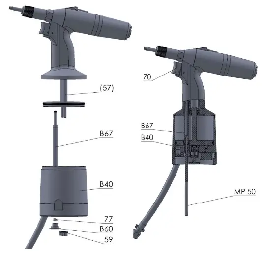
Assembly:
Put pos. B67 into pos. B40 and this complete put on pos. 57 (2x), screw on pos. 59 (2x) and tighten. Attach the MP50 to the bottom of the B67, press pos. 70, pos. B67 moves “down“, release pos. 70 and push to MP50. Pos. B67 must slide slightly. Put pos. 77 to recessing on the lower part pos. B67, screw pos. B60 into pos. B40. Pos. 59 (2x) secure with paint.
- Step 2
Disassembly:
Put pos. B26 with pos. 43 out of pos. B25 and pos. 57 (2x), put pos. 43 out of pos. B26. Then pour out the hydraulic oil from the riveting tool to the suitable container.
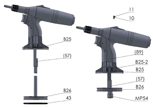
Assembly:
Pour hydraulic oil into pos. B9 (we recommended hydraulic oil HYSPIN AWHM 32 CASTROL or hydraulic oils grade HLP ISO VG 32), oil level up to 2. sealing (pos. B25-2) into pos. B25. Put pos. B26 on pos. 57 (2x) and into pos. B25. Then press and release pos. B26 toward pos. B9 cca 30 mm and wait until air bubbles stop leaking from the hydraulic system. After filling oil into hydraulic system of riveting tool (oil level up to 2. sealing (pos. B25-2) into pos. B25) press and release pos. B26 toward pos. B9, release pos. B26 and wait until air bubbles stop leaking from the hydraulic system (repeat this Step if necessary). Filling oil into hydraulic system of riveting tool. External surface pos. B26 lubricate with silicon paste LUKOSAN, put pos. B26 on and screw MP54 on pos. 57 to the stop position. Screw pos. 11 (ev. pos. 11 with pos. 10) out of pos. B9 with using socket-screw key no.3. Surplus oil leaks from pos. B9, screw pos. 11 with pos. 10 back to pos. B9 and tighten with using socket-screw key no.3. Take off MP54..
- Step 3
Disassembly:
Loosen and screw out pos. 57 (2x) with using nut and contranut on thread M6. Remove nut and contranut and screw pos. 57 (2x) to pos. B25 (thread M6). Pull both pos. 57 and pos. B25, put pos. 24 out.
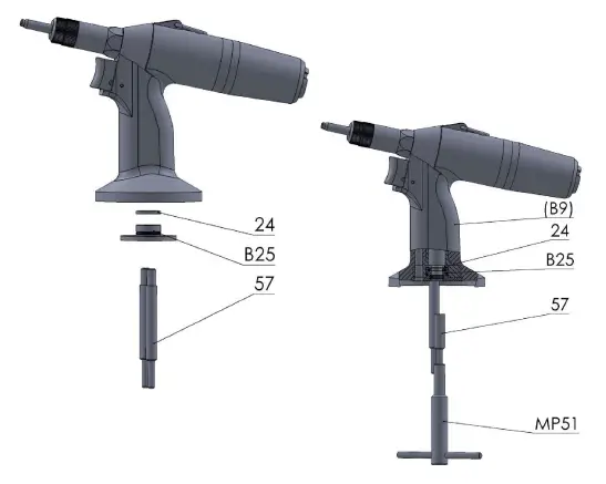
Assembly:
Put pos. 24 into pos. B9 groove to each other, put pos. B25 and screw pos. 57 (2x) on and tighten with using MP51.
- Step 4
Disassembly:
Screw pos. 2 and pos. 1 out. Screw pos. 5 out of pos. B9 with using wrench 24 and put pos. 6 out with using MP32.
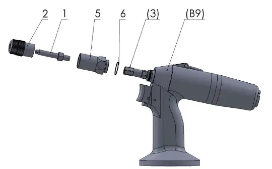
Assembly:
Put pos. 6 on pos. 5, screw pos. 5 to pos. B9 and tighten with using wrench 24. Screw pos. 1 on pos. 6 to the stop and move back a slight amount, so that hexagon pos. 1 and pos. 3 match. Put pos. 2 on pos. 1 and pos. 3, so that hexagon socket pos. 2 match with hexagon pos. 1 and pos. 3, screw on to pos. 5. Tighten the backnut in pos. 2 to the front of pos. 5.
- Step 5
Disassembly:
Screw pos. B18 out of pos. B9 with using hook spanner 30-32 (MP28). Be carefull, pos. B18 is under spring pressure pos. 19 and pos. 20. Gradually slide pos. 19, pos.20, pos. 21, pos. 22, pos. 23 out and put pos. 17 out with using MP32.
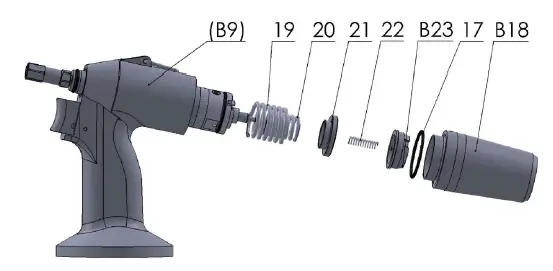
Assembly:
Put pos. 17 onto pos. B18, gradually put pos. B23, pos. 22, pos. 21, pos. 20 and pos. 19 into pos. B18. Screw this complete into pos. B9 and tighten with using hook spanner 30-32 (MP28). During assembly it is necessary to overcome the force of the springs pos. 19 and pos. 20.
- Step 6
Disassembly: Put out pos. B16.
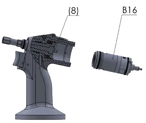
Assembly:
Put on pos. B16 and move around a slight amount so that hexagon pos. B16 and pos. 8 match, then move pos. B16 to the stop. Turn pos. 3 to check if the installation was successful, rotation in pos. B16 must be obvious and audible.
- Step 7
Disassembly:
Put wrenches 12 (2x) on pos. 3 and pos. 4, loosen and screw out pos. 3, put hex key on pos. 8 from the inside and screw out pos. 4.
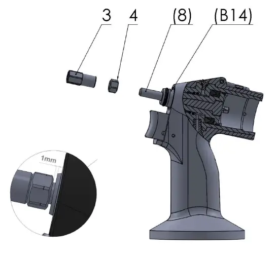
Assembly:
Screw pos. 4 on pos. 8 (recess in direction to pos. B14) so that the lenght between pos. 4 and pos. B14 is 1 mm (see the detail). Put several drops of glue LOCTITE 243 on thread of pos. 8, screw on pos. 3, put wrenches 12 (2x) on pos. 3 and pos. 4 and properly tighten towards pos. 4.
- Step 8
Disassembly:
Put pos. 8. out of pos. B14.
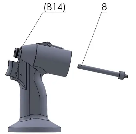
Assembly:
Put pos. 8 into pos. B14.
- Step 9
Disassembly:
Put pos. 7 out of pos. B14 with using MP32. Put pos. B14 out of pos. B9.
Be careful and do not damage the sealing in pos. B9!
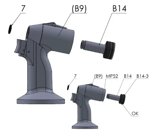
Assembly:
Screw MP52 into pos. B9. Lubricate external surface of pos. B14, inner surface of pos. B9 and related sealing of pos. B14 and pos. B9 with silicon paste LUKOSAN, secure pos. B14-3 in the pos. B14 with O ring 32/3 (see the picture, marked OK), than insert pos. B14 to the pos. B9 to the stop, pos. B14 must slide in pos. B9. Screw MP52 out of pos. B9. Put pos. 7 on pos. B14.
O ring 32/3 will loosen while inserting pos. B14 to pos. B9, it is not a part of the riveting tool!.
- Step 10
Disassembly:
Place a pin cca 2,8 mm in diametre to the pos. 68 and knock out with a hammer from pos. B9, put out pos. 70 and pos. 69.
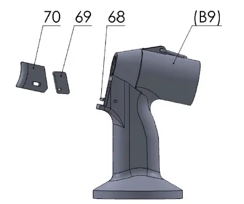
Assembly:
Put pos. 69 to pos. 70 and this complete put into pos. B9, put on pos. 68 and beat in with hammer and a pin cca 2,8 mm in diametre so that the pos. 68 is placed symmetrically in pos. B9 and secure both ends of pos. 68 with paint.
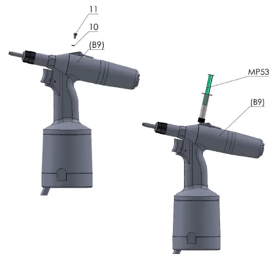
- Step 11
Oil filling after assembling the tool:
Connect the tool to the source of CA! Press and release the trigger several times.
Disconnect the tool from the source of CA! Unscrew pos. 11 with socket-screw key no.3. Fill hydraulic oil (from the supplied bottle with hydraulic oil) into MP53, take extra care to avoid air sucking, air must not be present in the hydraulic oil. Screw the MP53 tool into pos. B9 and inject the hydraulic oil into the tool. When the moving part of MP53 tool is released, the redundant oil is returned back to the MP53 tool. Unscrew MP53, screw pos. 11 with pos. 10 back to pos. B9 and tighten with using socket-screw key no.3.
Holding your world together®
Find your closest STANLEY Engineered Fastening location on
www.stanleyengineeredfastening.com/contact
For an authorized distributor nearby plea5e check
www.stanleyengineeredfastening.com/econtact/distributors

© 2022 Stanley Black & Decker, Inc.
Avdel®, POP® are registered trademarks of Stanley Black & Decker, Inc. and its affiliates. The names and logos of other companies mentioned herein may be trademarks of their respective owners. Data shown is subject to change without prior notice as a result of continuous product development and improvement policy. Your local STANLEY Engineered Fastening representative is at your disposal should you need to confirm latest information.


