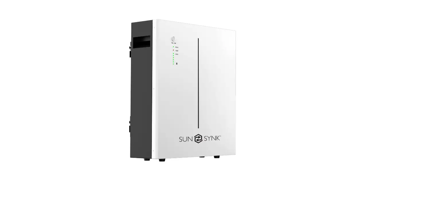
SUN SYNK SUN-BATT-5.32 Battery LFP Wall Mount
TECHNICAL DATA
| Nominal Voltage | 51.2 Vdc |
| Nominal Capacity | 104Ah |
| Battery Energy1 | 5320 Wh |
| Charge Voltage | 55.68~56.16Vdc |
| Discharge Voltage | 45.6-56.16 Vdc |
| Nominal Charge/Discharge Current | 50A |
| Nominal Charge/Discharge Power | 2500W |
| Max Charge / Discharge Current | 100A |
| Max Charge / Discharge Power | 5000W |
| Short Circuit Current | 350A |
| Communication | |
| Display | SOC status indicator, LED indicator |
| Communication | RS232, RS485, CAN |
| General Specification | |
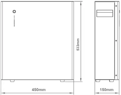
| Dimension( W×D×H mm ) | 450×150×533mm |
| Weight (Kg) | 45kg |
| Installation | Floor stand or Wall mounted |
| Working Temperature2 | -20ºC ~ 60ºC |
| Storage Temperature | ≤25ºC, 12 months ≤35ºC, 6 months ≤45ºC, 3 months |
| General Specification | |
| Operating / Storage / humidity | ≤ 95%RH |
| Max Operating Altitude | ≤2000m |
| IP Rating | IP20 |
| Cell Technology | LiFePO4, Lithium-iron Phosphate |
| Cycle life3 | 6000 Cycles @ 80% DOD / 25ºC / 0.5C, 60% EOL |
| Scalability | Max 8 batteries in parallel |
| Standard Compliance | |
| Certification | PACK:UN38.3, IEC62619, IEC61000, CELL:UN38.3, IEC62619, UL 1642, JET (more available upon re- quest) |
| Ordering and Deliverable Part | |
| Product ordering part | SUN-BATT-5.32 battery SUN-BATT-5.32 parallel cable SUN-BATT-5.32 to PCS cable |
PLEASE NOTE
Operating current derating according to cell voltage and battery temperature.
- Test conditions: 100% depth of discharge (DoD), 0.2C rate charge & discharge at 25ºC;
- Charge/discharge derating occurs when the operating temperature from -10ºC to 5 ºC & 45ºC to 55ºC.
- Condition apply. Refer to SUN-BATT-5.32 Warranty Letter
PRODUCT OVERVIEW
Brief Introduction
SUN-BATT-5.32 is a lithium battery with an operating voltage range between 45.6~56.16V. It is designed for residential energy storage applications and works together with a 48v battery hybrid inverter. SUN-BATT-5.32 is not suitable for supporting life-sustaining medical devices.
SUN-BATT-5.32 has built-in BMS (Battery Management System), which can manage and monitor cells informa-tion including voltage, current and temperature. Besides that, BMS can balance cells charging to extend cycle life. BMS has protection functions including over-dis- charge, over-charge, over-current and high/low temper-ature; the system can automatically manage charge state, discharge state and balance state.
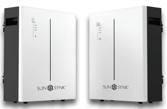
Multiple SUN-BATT-5.32 can be connected in parallel to expand capacity and power, 8 SUN-BATT-5.32 can be connected in parallel at most.
Interface Introduction
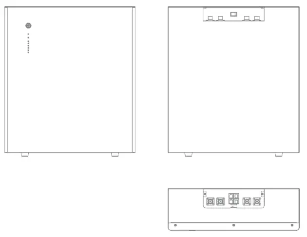
Switch ON/OFF
Switch ON
- For single SUN-BATT-5.32, switch ON rocker switch, then long press (more than 3 seconds) ON/OFF button on front panel, LED will flash, then battery will operate normally. L1 to L6 shows battery SoC, L7/L8 shows battery status.
- For multiple SUN-BATT-5.32 in parallel, switch ON rocker switch on all batteries, long press (more than 3 sec-onds) ON/OFF button of MASTER battery, LED will flash, battery system will automatically encode and assign ID to each slave battery, then battery system will operate normally.
Switch OFF
- Press start button of Master PACK more than 3s and then release the button, the master pack will shut down after all slave packs shut down(Sleep mode) .
- For single SUN-BATT-5.32, switch OFF rocker switch.
- For multiple SUN-BATT-5.32 in parallel, switch OFF rocker switch on MASTER battery first. Then switch OFF rocker switch on all slave batteries
LED Indicator Definition
Note
- flash 1 – 0.25s light / 3.75s off
- flash 2 – 0.5s light / 0.5s off
- flash 3 – 0.5s light / 1.5s off
| RUN | ALM | Battery Level Indicator | Discriptions | |||||||
| Status | L8 | L7 | L6 | L5 | L4 | L3 | L2 | L1 | ||
| Shut down | OFF | OFF | OFF | OFF | OFF | OFF | OFF | OFF | All OFF | |
| Standby | Flash 1 | OFF | According to the battery level | Indicates Standby | ||||||
|
Charging | Normal | Light | OFF | According to the battery level | The highest capacity indicator LED flashes (flash 2),others lighting | |||||
| Full Charged | Light | OFF | Light | Light | Light | Light | Light | Light | Turn to standby status when charger off | |
| Protection | OFF | Light | OFF | OFF | OFF | OFF | OFF | OFF | Stop charging | |
| Dis- charge | Normal | Flash 3 | OFF | According to the battery level | ||||||
| UVP | OFF | OFF | OFF | OFF | OFF | OFF | OFF | OFF | Stop charging | |
| Protection | OFF | Light | OFF | OFF | OFF | OFF | OFF | OFF | Stop discharge | |
| Fault | OFF | Light | OFF | OFF | OFF | OFF | OFF | OFF | Stop charging and Discharge | |
Charging Battery Level Indicators Instructions
| Status | Charging | ||||||||
| Battery Level Indicator | L8 | L7 | L6 | L5 | L4 | L3 | L2 | L1 | |
|
Battery Level (%) | 0 ~ 17% |
Light |
OFF | OFF | OFF | OFF | OFF | OFF | Flash 2 |
| 18~ 33% | OFF | OFF | OFF | OFF | Flash 2 | Light | |||
| 34 ~ 50% | OFF | OFF | OFF | Flash 2 | Light | Light | |||
| 51 ~ 66% | OFF | OFF | Flash 2 | Light | Light | Light | |||
| 67 ~ 83% | OFF | Flash 2 | Light | Light | Light | Light | |||
| 84 ~ 100% | Flash 2 | Light | Light | Light | Light | Light | |||
| Full Charged | Light | Light | Light | Light | Light | Light | |||
Discharging Battery Level Indicators Instructions
| Status | Discharge | ||||||||
| Battery Level Indicator | L8 | L7 | L6 | L5 | L4 | L3 | L2 | L1 | |
|
Battery Level (%) | 0 ~ 17% |
Flash 3 |
OFF | OFF | OFF | OFF | OFF | OFF | Light |
| 18~ 33% | OFF | OFF | OFF | OFF | Light | Light | |||
| 34 ~ 50% | OFF | OFF | OFF | Light | Light | Light | |||
| 51 ~ 66% | OFF | OFF | Light | Light | Light | Light | |||
| 67 ~ 83% | OFF | Light | Light | Light | Light | Light | |||
| 84 ~ 100% | Light | Light | Light | Light | Light | Light | |||
CAN / RS485 Port
CAN / RS485 Communication Terminal (RJ45 port), connect to inverter, follow CAN / RS485 protocol.
| PIN | Definition |
| Pin 1, Pin 8 | RS485-B ( to PCS, reserved ) |
| Pin 2, Pin 7 | RS485-A ( to PCS, reserved ) |
| Pin 3 | NC |
| Pin 4 | CANH ( to PCS ) |
| Pin 5 | CANL ( to PCS ) |
| Pin 6 | GND |
RS232 Port
RS232 Communication Terminal (RJ45 port) follow RS232 protocol, for manufacturer or professional engi-neer to debug or service.
| PIN | Definition |
| Pin 1, Pin 8 | GND |
| Pin 2, Pin 7 | RS232_TX |
| Pin 3, Pin 6 | RS232_RX |
| Pin 4, Pin 5 | NC |
INSTALLATION GUIDE
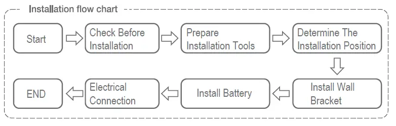
Checking Before Installation
Checking Outer Packing Materials
Packing materials and components may be damaged during transportation. Therefore, check the outer pack-ing materials before installing the battery. Checking the surface of packing materials for damage, such as holes and cracks. If any damage is found, do not unpack the battery and contact the dealer as soon as possible. You are advised to remove the packing materials within 24 hours before installing the battery.
Checking Deliverables
After unpacking the battery, check whether deliverables are intact and complete. If any damage is found or any component is missed, contact the dealer.
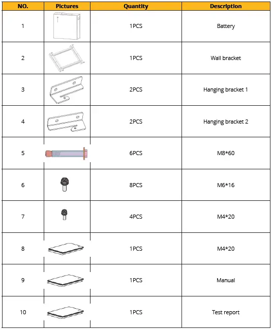
The below table shows the components and mechanical parts that should be delivered.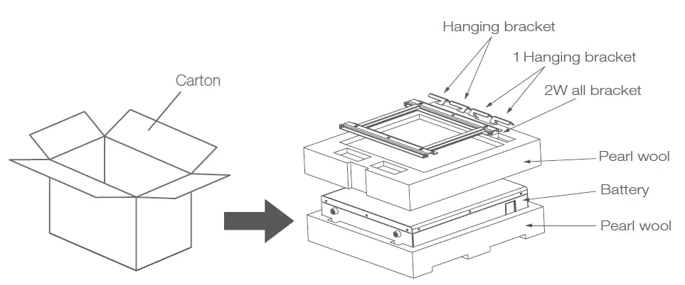
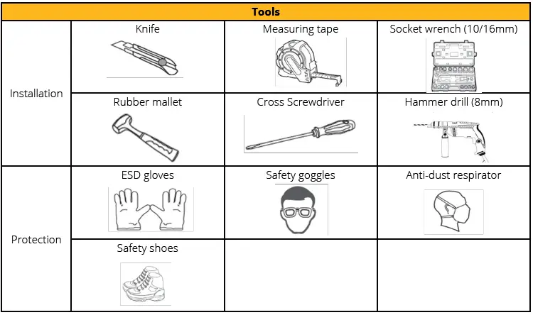
PARTS
Tools
Installation Requirements
Installation Environment Requirements
- Install the battery in the indoor environment.
- Place battery in secure location away from children and animals.
- Do not place the battery near any heat sources and avoid sparks.
- Do not expose the battery to moisture or liquids.
- Do not expose the battery to direct sunlight.
Installation Carrier Requirements
- Only mount battery on fire resistant building. Do not install batteries on flammable buildings.
- Battery is quite heavy, make sure the wall/ground can meet the load bearing requirements.
Installation Instructions
Dimensions
Minimum mounting distance between battery pack and equipment: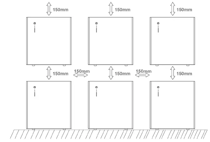
Installation Procedure
STEP 1: Drill the hole with an 10mm drill bit as follows and fix the wall bracket to the wall.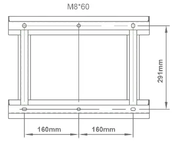
STEP 2: Install the hanging bracket.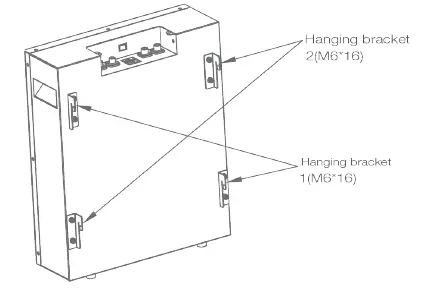
STEP 3: Hang SUN-BATT-5.32 on the wall bracket and tighten it.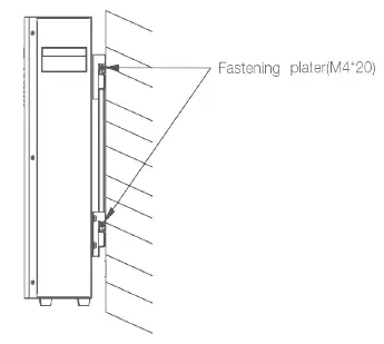
STEP 4: Connect to ground.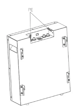
STEP 5: Connect power cable.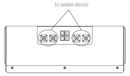
STEP 6: Connect communication cable.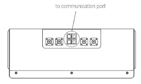
STEP 7: Connect communication cable.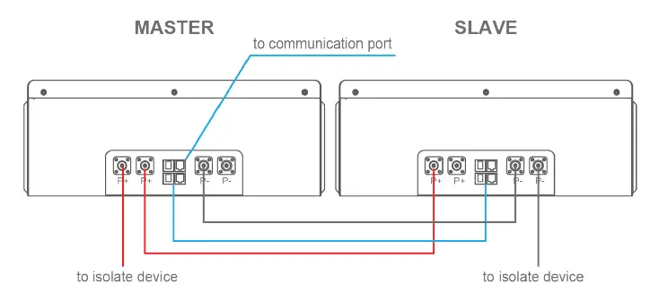
BATTERY POWER AND COMMUNICATION CONNECTIONS
Parallel Cascade Connection
Applicable scenario: PCS with 100A charge/discharge current connect to SUN-BATT-5.32.
Power Cable Wiring Instructions: Each SUN-BATT-5.32 has two pairs of power cable terminals, two P+, and two P-. The connec- tion terminals of each pair have the same function.
Single Module: In a single module application, any of the terminals of each pair can be used.
Parallel System
- Multiple batteries can be connected in parallel to expand the capacity and power. When using multiple bat-teries in parallel, one will operate as a master and the others as
- slaves. One of the Master pack P+ terminals should connect to the PCS, and the other should connect to another battery for capacity expansion.
- One of the P- terminals of the last Slave pack should connect to PCS, and the other should connect to another battery for capacity expansion.
- For the other Slave packs, each P terminal should be connected to another battery’s terminal.
PLEASE NOTE
The connection to the protection devices should use the P+ terminal from the Master pack and the P- terminal from the last Slave pack.
Communication Cable Connections
The Master battery can automatically identify the Slaves batteries connected in parallel using its internal soft-ware control. The communication terminals Port In and Port Out (RJ45 port) are integrated with the signal for automatic coding function.
PLEASE NOTE: All parallel power cables should be of the same length.
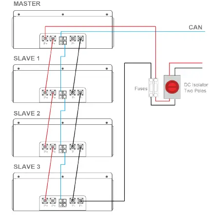
The following describes the connections of a system with four batteries packs, one Master, and three Slaves.
- The CAN communication port of the Master pack should connect to PCS;
- Port In from the Master pack should not be connected;
- The Port Out from the master PACK should connect the Port In of the first slave PACK using a parallel communication wire;
- The Port Out of the first Slave pack should connect to the Port In of the second Slave PACK;
- Following the same pattern, the Port Out of the second Slave pack should connect to the Port In of the third Slave PACK;
- The Port Out of the third and last slave PACK should not be connected.
Busbar Connection
Applicable scenario
- PCS with 200A charge/discharge current connect to SUN-BATT-5.32.

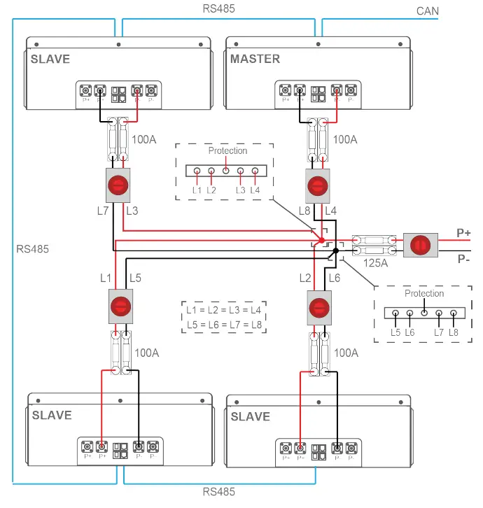
PLEASE NOTE
All parallel power cables should be of the same length: (L1 = L2 = L3 = L4 = L5 = L6 = L7 = L8)
- You are advised to use the EV power cables with minimal size of 25 mm2 or 3AWG (600V, 125A) and length min.1500mm.
- The P+ and P- power line between the busbar and the PCS should be able to support 200A rated current, You are advised to use the EV power cable with size min. 50 mm2 or 0AWG (600V, 210A).
- Before assembling Power cable, label the cable polarities correctly to ensure correct ca-ble connections and identification.
- The power cables installation and connection must be carried out by trained profession-als.
MAINTENANCE
Recharge Requirements During Normal Storage
Battery should be stored in an environment with temperature range between -10°C ~ +45°C, and maintained regularly according to following table with 0.5C (25A) current till 40% SoC after long storage time.
| Recharge Conditions When In Storage | |||
| Storage Environment Temperature | Relative Humidity of Storage Environment | Storage Time | SOC |
| Below -10ºC | / | prohibit | / |
| -10~25ºC | 5%~70% | ≤12 months | 30%≤SOC≤60% |
| 25~35ºC | 5%~70% | ≤6 months | 30%≤SOC≤60% |
| 35~45ºC | 5%~70% | ≤3 months | 30%≤SOC≤60% |
| Above 45ºC | / | prohibit | / |
Recharge Requirements When Over Discharged
Over discharged (90% DoD) battery should be recharged according to following table, otherwise over dis-charged battery will be damaged.
| Recharge conditions when battery is over discharged | ||
| Storage Environment Temper– ature | Storage Time | Note |
| -10~25ºC | ≤15 days | Battery Pack disconnected from PCS |
| 25~35ºC | ≤7 days | |
| 35~45ºC | <12 hours | Battery Pack connected to PCS |
CONTACT US
- Email us: [email protected]
- Call us UK: +44 151 8324300
- VAT Number: 175669460
- UK Address: Sunsynk, 17 Turnstone business park, Mulberry Avenue. Widnes, Cheshire, WA8 OWN.


