![]() W712 Linkvil RoIP Gateway
W712 Linkvil RoIP Gateway
Installation Guide
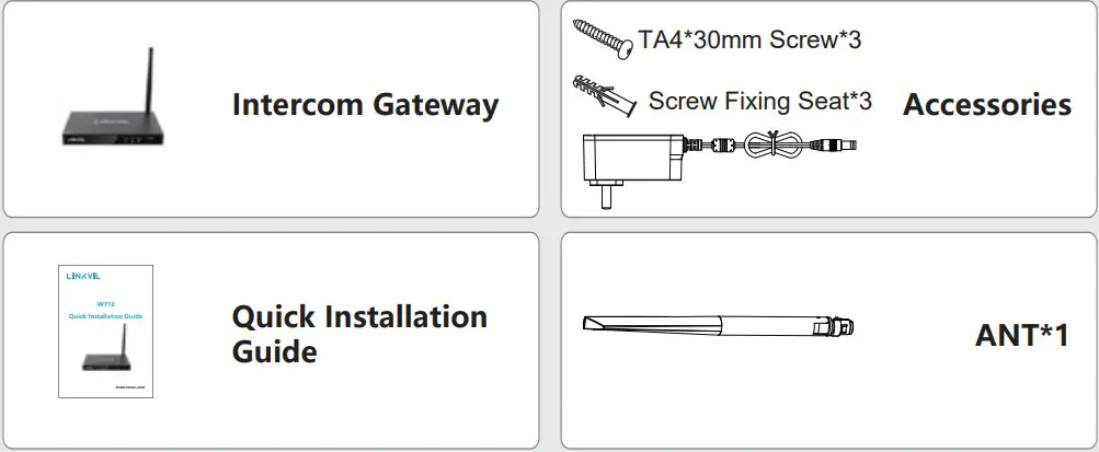
Package Contents
Physical specification
| Device size | 126*209*26.3mm |
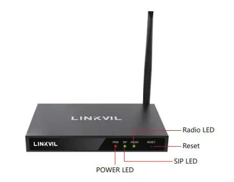
- Panel

- Interface description
The interface on the back of the device can be used for power supply, network, TF card, U disk, etc. The connection is shown as follows:
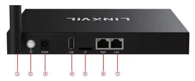
| 1 | ANT Interface |
| 2 | GND Interface |
| 3 | Power interface: 12V/2A input, note that the inside is positive and the outside is negative |
| 4 | USB interface: Can be connected to external USB flash drive, the maximum support is 128G |
| 5 | TF card interface, can be connected to external U disk, the maximum support 128G |
| 6,7 | WAN/LAN interface: standard R145 interface, 10/100M self-adaptive, it is recommended to use Category 5 or Super Category 5 network cable |
Installation
Setp 1: Installation preparation
A. Power Supply check
- Check whether the voltage of dc power supply or external power supply in the range of the working voltage of the product(12V/2A).
B. Product Check - After the device is powered on and started, check whether the device is running properly by observing the status of all indicators on the front panel. For details, see “Basic Function Operations”.
C. Installation of accessories - If the device is not enabled, you need to install the narrowband antenna, power adapter, and LAN cable.
D. Installing the Antenna (Figure 1) - Insert the threaded end of the antenna into the narrow band connector and tighten it
 E. Install network cables (Figure 2)
 - Connect the network cable to WAN network port (Ethernet) for POE power supply (802.3at).
 F. Install the power adapter (Figure 3)
 - Plug the cable connector of the power adapter into the 12V power connector of the device.
 E. Install network cables (Figure 2)
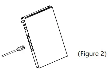 F. Install the power adapter (Figure 3)
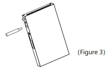
Device IP address
Device IP address query method:
Open the iDoorPhone Network Scanner. Press the Refresh button to search the device and find the IP address.
( Download address: http://download.fanvil.com/tool/iDoorPhoneNetworkScanner.exe ).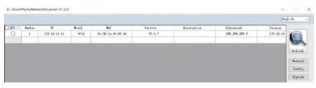 Gateway setting
Step 1: Log in to the device web page
Input IP address (e.g. http://192.168.1.128) into address bar of PC’ s web browser. The default user name and password are both admin., 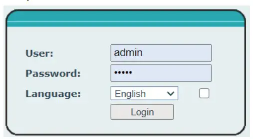 Step 2: Add the SIP account.
Set SIP server address, port, user name, password and SIP user with assigned SIP account parameters.
Select “Activate” , and then click Apply to save this setting. 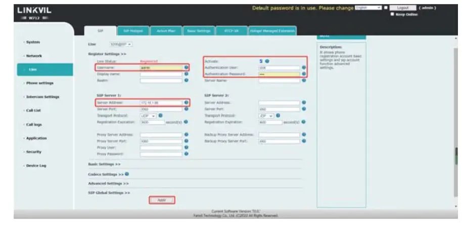 Step 3: Set up the intercom channel
Set the parameters related to the channel related to the intercom, as shown below. Click “Submit”, and intercom communication requires the same frequency and unique parameters
Type: analog channel or digital channel
Transmit frequency/Receive frequency: The intercom frequency of the call
Power: length of transmitting distance
Recv Sub / Send Sub Tone: analog channel specific parameters
Channel Spacing: analog channel specific parameters Time Slot: Digital channel specific parameters
Colour Code: Digital channel specific parameters 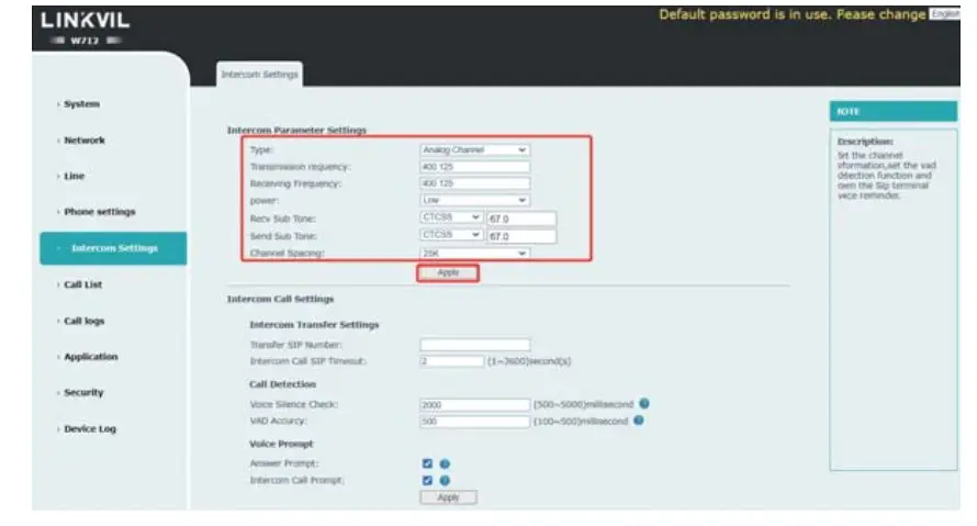 Note: The default transmitting power is low. You are advised to change it to high in normal use.
Step 4: Set intercom parameters
To set the multicast address of the gateway: 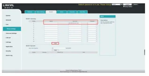 Set an intercom call number. The intercom transfers the call to the corresponding phone when PTT is pressed. Other parameters are as follows:
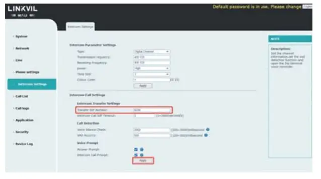
Step 5: Use of intercom functions:
General mode call:
The IP phone dials the registered sip number of the gateway, and the gateway sets the same channel parameters as the intercom. When the IP phone speaks, the IP phone automatically forwards the call to the intercom. When the IP phone does not speak, the intercom presses the PTT key to automatically forwards the call to the IP phone
Call in PTT mode:
Set the PTT key on the phone to the sip number or multicast address registered on the gateway, set the channel parameters on the gateway to be the same as those on the intercom, set the intercom transfer number on the gateway, press the PTT key to automatically forward the call to the intercom, release the PTT key to end the intercom, and press the PTT key on the intercom to automatically call the number specified in the intercom transfer number. Then release the PTT key to end the intercom.
Step 6: Application scenario
| Serial number | Application scenarios | Intercom transmission distance (4W power) |
| 1 | Indoor building | Maximum 29 floors |
| 2 | Community | The maximum radius is 1500 meters |
| 3 | Open areas of the city | Maximum radius of 2900 meters |
![]()


