NXP UM11933 RPi-CAM-MIPI Board
Product Information
Revision: 1 — 4 July 2023
Document Information
| Information | Content |
|---|---|
| Keywords | RPi-CAM-MIPI, AR0144, i.MX93, MCIMX93-EVK, IAS, Raspberry PI |
| Abstract | The RPi-CAM-MIPI accessory board is a MIPI-CSI camera module adapter, AR0144 CMOS image sensor with ON Semiconductor IAS interface by default, which features 1/4-inch 1.0 Mp with an active-pixel array of 1280H x 800V. The bypassable on-board ISP chip allows it to be used with a wide range of SoCs. This accessory board connects to the i.MX9 EVK board through the 22P/0.5mm Pitch FPC cable. |
RPi-CAM-MIPI Overview
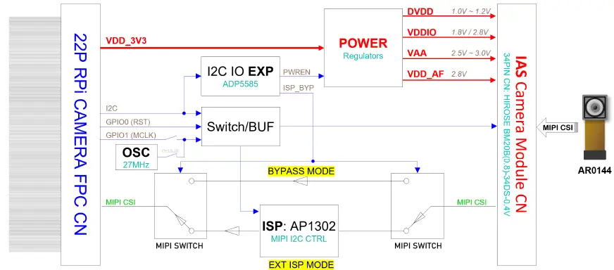
The RPi-CAM-MIPI kit is an MIPI CSI camera adapter board designed to connect different kinds of camera sensors with the ON Semiconductor IAS interface. The bypassable on-board ISP (ON Semiconductor AP1302) chip allows it to be used with a wide range of SoCs.
This document includes the RPi-CAM-MIPI introduction and board setup and configurations and provides detailed information on the overall design and usage of the RPi-CAM-MIPI board from a hardware system perspective.
Acronyms and Abbreviations
| Term | Description |
|---|---|
| BGA | Ball Grid Array |
| CSI-2 | Camera Serial Interface 2 |
| DNP | Do Not Populate |
| HS | High-Speed |
| I2C FD | Flexible Data rate Inter-Integrated Circuit |
| GPIO | General-Purpose Input/Output |
| ISP | In-System Programming |
| LDO | Low Dropout Regulator |
| MIPI | Mobile Industry Processor Interface |
| LED | Light-Emitting Diode |
| Document | Description | Link / How to Access |
|---|---|---|
| i.MX 93 Applications Processor Reference Manual | This document is intended for system software and hardware developers and application programmers who want to develop products with the i.MX 93 MPU. | IMX93RM |
| i.MX 93 Industrial Application Processors Data Sheet | This document provides information about electrical IMX93IEC characteristics, hardware design considerations, and ordering information. | |
| i.MX93 Hardware Developer’s Guide | This document aims to help hardware engineers design and test their i.MX 93 processor-based designs. It provides information about board layout recommendations and design checklists to ensure first-pass success and avoidance of board bring-up problems. | IMX93HDG |
Board Kit Contents
| Item description | Quantity |
| RPi-CAM-MIPI | 1 |
| AR0144 CMOS sensor | 1 |
| 22-pin / 0.5-mm pitch FPC cable | 1 |
| RPI-CAM-MINISAS | 1 |
Block diagram
Board pictures
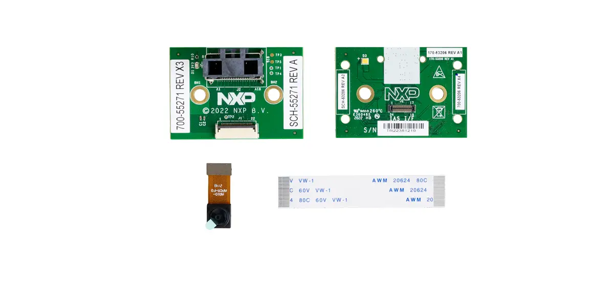
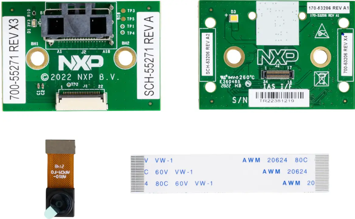
The top-side and bottom-side view of the RPi-CAM-MIPI board, AR0144 camera, and FPC cable. RPI-CAM-MINISAS is the converter board which can support a 22-pin FPC connector converted to a MiniSAS connector, or a MiniSAS connector converted to a 22-pin FPC connector.
RPI-CAM-MIPI BOTTOM view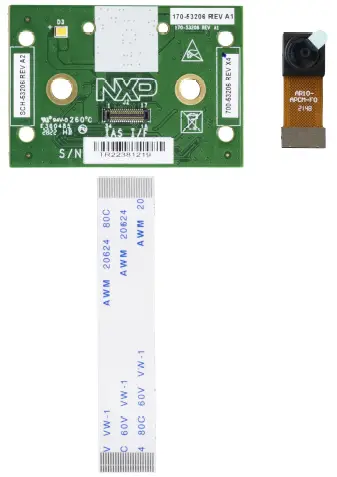 RPI-CAM-MIPI TOP view
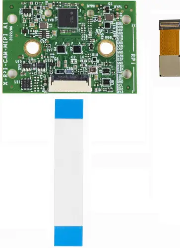 RPI-CAM-MIPI connection with MCIMX93-EVK
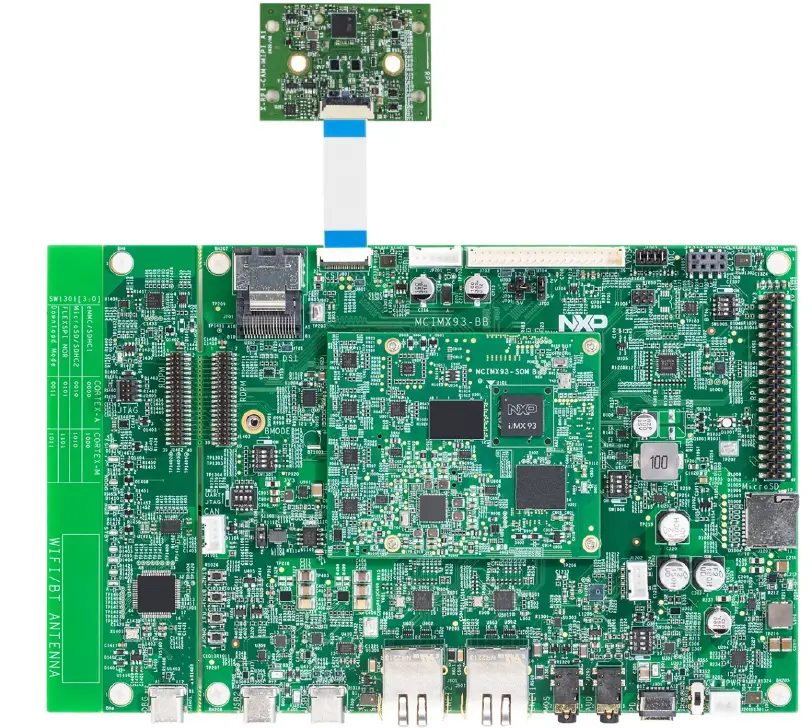
Board features
| Board feature | Target processor feature used | Description |
| Interfacing with the main board | – | A 22-pin connector is used for the RPI-CAM-MIPI board. A 22-pin / 0.5- mm FPC cable is used between RPI-CAM-MIPI and the main board. |
| Power | 3.3 V | The RPI-CAM-MIPI board can be powered by 3.3 V from the motherboard. |
| I2C | I2C | RPI-CAM-MIPI is configured through the I2C interface on the motherboard. |
| MIPI CSI | MIPI CSI |
|
| IO0/IO1 | GPIO |
|
Connectors
The connector position on the board. Table 5 describes the RPI-CAM-MIPI board connectors. Table 5. RPI-CAM-MIPI connectors
| Connector | Description | Connector type | Reference section |
| J1 | RPi interface connected with motherboard | 22-pin FPC connector | Section 2.1 |
| J2 | IAS-compatible interface for camera | B2B 34-pin connector | Section 2.2 |
Flash LEDs
The RPI-CAM-MIPI board has a Light-Emitting Diode (LED) D3, which can be used as a camera flash LED or as a torch.
RPI-CAM-MIPI functional description
22-pin RPi interface
A 22-pin FPC/FFC connector is designed on the RPI-CAM-MIPI board. The pin definition on the connector is compatible with the Raspberry PI camera 22-pin interface. The detailed definition list is in Table 6.
22-pin RPi interface definition
| Pin # | Net name | Description |
| 1 | VDD_3V3 | 3.3 V power input |
| 2 | I2C_SDA | I2C SDA signal |
| 3 | I2C_SCL | I2C SCL signal |
| 4 | GND | Ground |
| 5 | IO1 (CSI_MCLK) | GPIO1 default used as MCLK input |
| 6 | IO0 (CSI_nRST) | GPIO0 default used as Reset input |
| 7 | GND | Ground |
| 8 | CMF_CSI_DP3 | MIPI serial data, lane 3, differential P |
| 9 | CMF_CSI_DN3 | MIPI serial data, lane 3, differential N |
| 10 | GND | Ground |
| 11 | CMF_CSI_DP2 | MIPI serial data, lane 2, differential P |
| 12 | CMF_CSI_DN2 | MIPI serial data, lane 2, differential N |
| 13 | GND | Ground |
| 14 | CMF_CSI_CKP | MIPI serial clock differential P |
| 15 | CMF_CSI_CKN | MIPI serial clock differential N |
| Pin # | Net name | Description |
| 16 | GND | Ground |
| 17 | CMF_CSI_DP1 | MIPI serial data, lane 1, differential P |
| 18 | CMF_CSI_DN1 | MIPI serial data, lane 1, differential N |
| 19 | GND | Ground |
| 20 | CMF_CSI_DP0 | MIPI serial data, lane 0, differential P |
| 21 | CMF_CSI_DN0 | MIPI serial data, lane 0, differential N |
| 22 | GND | Ground |
Camera interface IAS
A 34-pin board-to-board connector is designed for the camera sensor connection. The PIN definition follows the ON Semiconductor Imager Access System (IAS) specification. Table 7 shows the pin assignment for the connectivity of a standard IAS camera module. These pins use Hirose BM20B(0.8)-30DP-0.4V(51).
34-pin IAS interface definition
| Pin # | Pin name | Pin # | |
| 1 | GPIO1/VDD_AF/Vpp | GPI3/SADDR/ VDD_AF | 34 |
| 2 | GND | GND | 33 |
| 3 | GND | MCLK | 32 |
| 4 | DATA1_P/SLVS0_P | GND | 31 |
| 5 | DATA1_N/SLVS0_N | DATA2_P/SLVS1_P | 30 |
| 6 | GND | DATA2_N/SLVS1_N | 29 |
| 7 | CP_P | GND | 28 |
| 8 | CP_N | DATA3_P/SLVS2_P | 27 |
| 9 | DGND | DATA3_N/SLVS2_N | 26 |
| 10 | DATA4_P/SLVS3_P | GND | 25 |
| 11 | DATA4_N/SLVS3_N | DVDD | 24 |
| 12 | GND | DVDD | 23 |
| 13 | VDDIO | SDA | 22 |
| 14 | SCL | RESET/XSHUTDOWN | 21 |
| 15 | GPIO0/Flash | GPI2/Trigger | 20 |
| 16 | GND | GND | 19 |
| 17 | VAA | VAA | 18 |
The following are the IAS pinning notes:
- The pinning is designed to offer three supply rails for the sensor. Follow the sensor data sheet for exact voltage requirements.
- Digital supply, typically in the range from 1.0 V to 1.2 V.
- I/O supply, typically in the range of 1.8 V.
- Analog supply, typically in the range from 2.5 V to 3.0 V.
- Pin# 1 (VDD_AF/VPP/GPIO1).
- If the module has a VCM for AF, pin #1 is used as VDD_AF (2.8 V).
- If the module requires an external VPP to program the OTPM, pin #1 is used as the VPP. For the Vpp value, see the individual sensor datasheet.
- If the module has GPIO1, pin #1 is used as GPIO1.
- Pin #34 (VDD_AF/SADDR/GPI3).
- If the module has a VCM for AF, pin #34 is used as VDD_AF (2.8 V). In this case, if the sensor has an SADDR pin, it must be grounded inside the module (default I2C slave address).
- If the sensor has an SADDR pin, pin #34 is the SADDR.
- If the sensor has a GPI3, pin #34 is the GPI3.
- For sensors selected for IAS modules, it has either SADDR or GPI3.
- Pin #15 is optional for GPIO0 and flash pin.
- Pin #20 is optional for GPI2 and trigger pin.
- At this time, there are no maximum power draw requirements for IAS modules. Any total power usage below 500 mW should cause no problem. The total power draw between 500 mW and 1 W should be reviewed with the target system (adapter boards and end-reference platform). For modules that draw more than 1 W of power, consider using additional external supply with a direct connection to the module or a specially designed adapter (header) board.
Power design
The RPI-CAM-MIPI board includes four power regulators and one LED driver.
Camera sensor power rails
| Power | Description | Value |
| DVDD | Digital power supply | 1.05 V / 1.2 V |
| VAA | Analog power supply | 2.7 V / 2.8 V |
| VDDIO | I/O power supply | 1.8 V |
| VDD_AF | Voice Coil Motor (VCM) power supply | 2.8 V |
All the power regulators are controlled by enable signals, which come from the ADP5585ACPZ-01-R7 I2C GPIO expander. The power-up sequence is different for different camera sensors.
The ON Semiconductor AR0144 sensor power-up sequence.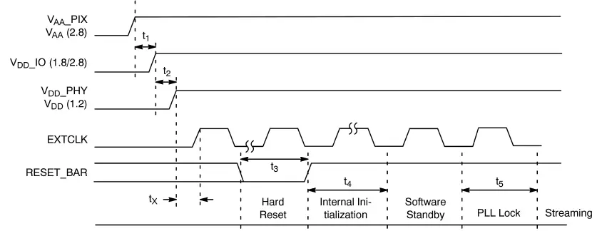 Power-up sequence
| Symbol | Definition | Min | Typ | Max | Unit |
| t1 | VAA/VAA_PIX to VDD_IO | 0 | 10 | – | μs |
| t2 | VDD_IO to VDD/VDD_PHY | 0 | 10 | – | μs |
| tX | Xtal Settle Time | – | 30 | – | ms |
| t3 | Hard Reset | 1 | – | – | ms |
| t4 | Internal Initialization | 160000 | – | – | EXTCLKs |
| t5 | PLL Lock Time | 1 | – | – | ms |
ISP
The ON Semiconductor AP1302 (U9) external ISP chipset is supported on the RPI-CAM-MIPI board. An external ISP can be bypassed by software configuration through the ISP_BYP control signal.
15-pin RPi camera usage
The RPI-CAM-MIPI board can be connected with different motherboards with the Raspberry PI camera-compatible interface. There are two types Raspberry PI camera interfaces; the 15-pin / 1.0-mm FPC/FFC connector and the 22-pin / 0.5-mm FPC/FFC connector. If a 15-pin connector is supported on the motherboard, a 22-pin to 15-pin cable can be used.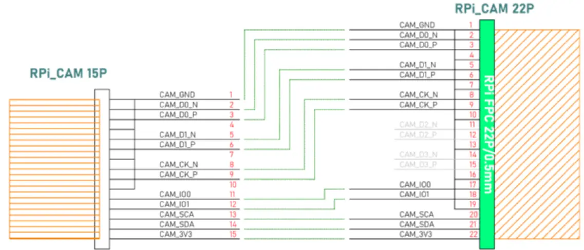 15-pin to 22-pin FPC/FFC cable example
I2C devices on RPI-CAM-MIPI
All the I2C devices on RPI-CAM-MIPI are shown in Table 10. Table 10. I2C devices on base board.
| Part | Device | I2C address (7-bit) | Port | Speed | Voltage | Description |
| U9 | AP1302CSSL00SMGA0 | 0x3C (0b’0111100x) | RPi-I2C | 1 MHz Fm+ / 3.4 MHz HS | 1.8 V | External ISP |
| U103 | ADP5585ACPZ-00- R7 | 0x34 (0b’0110100x) | RPi-I2C | 1 MHz Fm+ | 3.3 V | I2C GPIO expander |
| Sensor #1 | AR0144 | 0x10 (0b’0010000x) | RPi-I2C | 400 KHz | 1.8 V | 1/4-inch 1.0 Mp GS |
| Sensor #2 | AR0430 | 0x36 (0b’0110110x) | RPi-I2C | 1 MHz Fm+ | 1.8 V | 1/3.1-inch 4 Mp ERS |
| Sensor #3 | AR1335 | 0x36 (0b’0110110x) | RPi-I2C | 1 MHz Fm+ | 1.8 V | 1/3.2-inch 13 Mp ERS |
PCB information
The RPI-CAM-MIPI board is made with a standard six-layer HDI technology. The material is FR-4 and the PCB stack-up information.
RPI-CAM-MIPI board stack-up information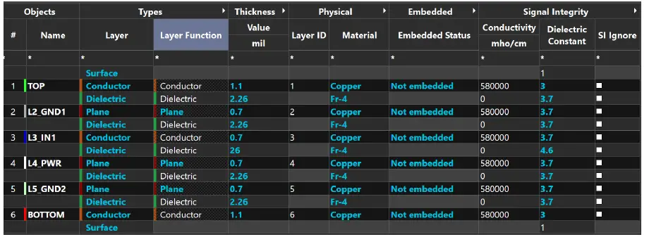 RPI-CAM-MIPI PCB stack-up
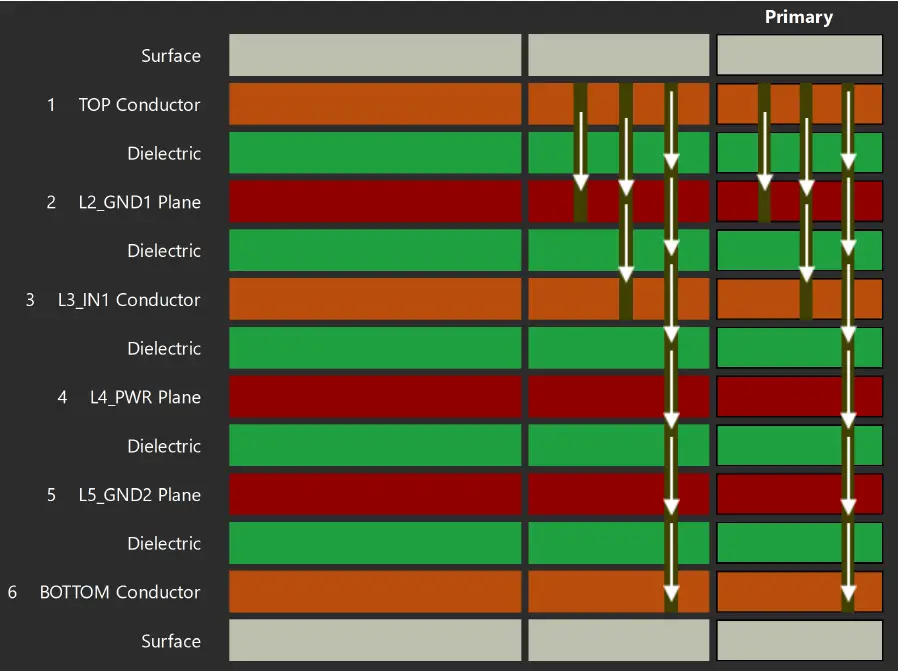
Getting started
Connecting the RPI-CAM-MIPI board
The RPI-CAM-MIPI board can be connected to the MCIMX93-EVK board via a FPC cable. The connection between them is shown in Figure 4.
The AR0144 camera sensor should be connected to J1 on the RPI-CAM-MIPI board, as shown in Figure 2.
Getting the pre-built images
The pre-built binary images for the MCIMX93-EVK board are available starting with Linux BSP 6.1.1_1.0.0. The RPI-CAM-MIPI drivers are integrated into the pre-built binary images.
The pre-built binary images can be downloaded from the NXP IMXLINUX webpage. See the i.MX Linux User’s Guide (document IMXLUG) for how to flash the pre-built images and booting the Linux OS.
Getting the AP1302 firmware
Perform the following steps to get the AP1302 firmware:
- Download the “ap1302_60fps_ar0144_27M_2Lane_awb_tuning.bin” file from the ON Semiconductor github page by following the README.
- Rename it to “ap1302.fw”.
- After booting the Linux OS, copy the file to the target board under “/lib/firmware/imx/camera” and reboot.
Running the camera module
If everything goes well, you will see the following log after booting the Linux OS: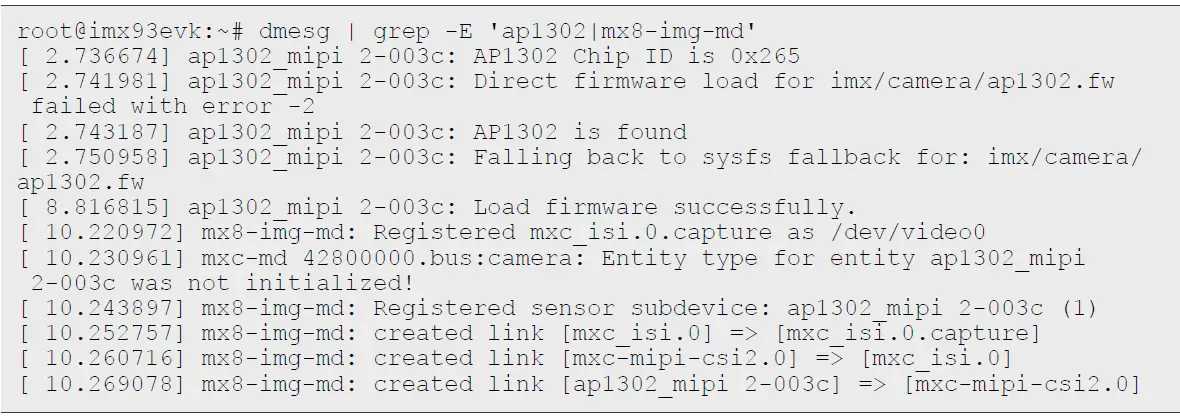
Software introduction
The drivers for the RPi-CAM-MIPI board are developed by NXP and are already integrated into the Linux BSP for the i.MX application processors. In the default Linux BSP release, it can only support sourcing an image stream from the AR0144 camera sensor with the RPi-CAM-MIPI board. The on-board ISP AP1302 (firmware required) is enabled by default.
Driver source code
The driver source code is available from the NXP Linux kernel repository.
- AP1302 + AR0144 camera sensor V4L2 driver: “drivers/media/i2c/ap1302.c”
- ADP5585 I2C GPIO expander driver: “drivers/mfd/adp5585.c”, “drivers/gpio/gpio-adp5585.c”, and “drivers/pwm/pwm-adp5585.c”
The AP1302 firmware can be downloaded from the ON Semiconductor github page.
Device tree configuration
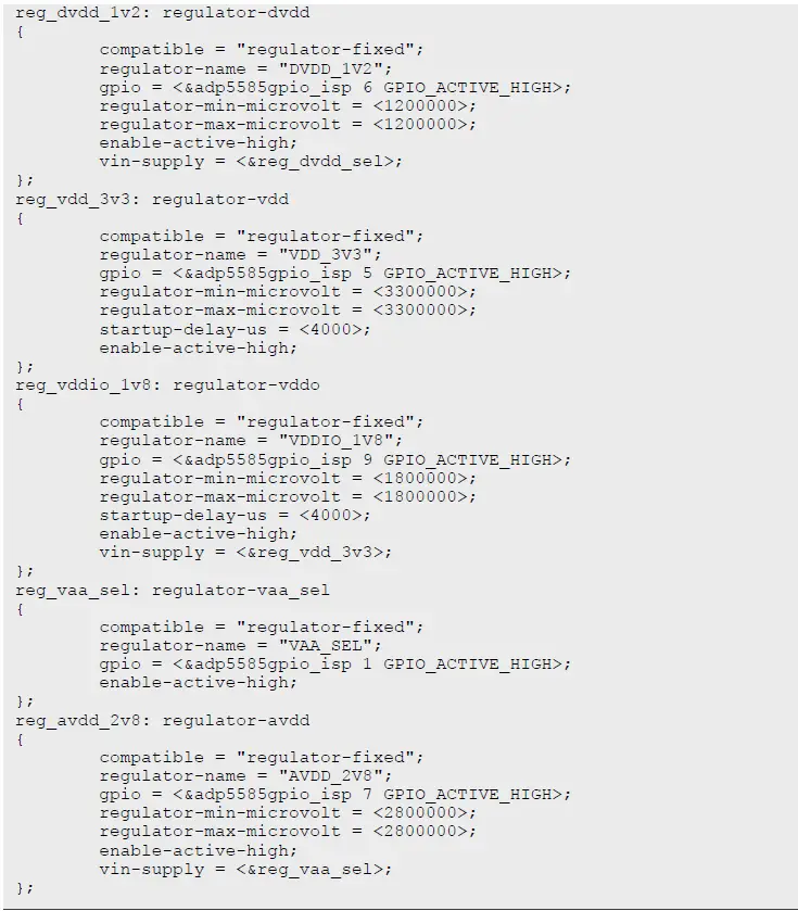
This section contains the example device tree for the RPi-CAM-MIPI board. It contains two I2C devices: ADP5585 GPIO expander and AP1302 (AR0144 connected) camera module.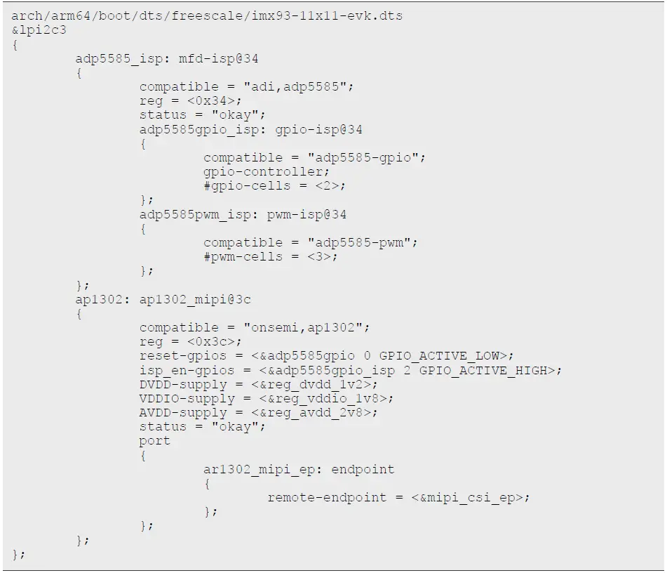 The ADP5585 GPIO expander is used to configure the power supplies’ voltages, control the power-up sequence, and enable or bypass the on-board ISP AP1302. The example configuration for AP1302 (enabled) and AR0144 is below. It is implemented following the Linux regulator framework. If you want to connect another camera sensor to the RPi-CAM-MIPI board, these regulators must be configured to match the power requirement of the selected camera sensor.
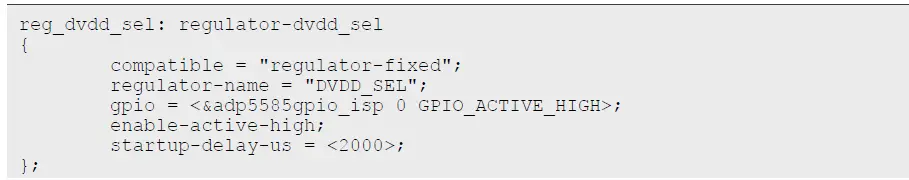
How to use the camera module
The AP1302 + AR0144 camera driver is developed following the V4L2 framework in NXP Linux BSP. You can use the “media-ctl”, “v4l2-ctl”, and “gst-launch” command-line utilities to do some camera use cases.
- Get the topology of the capture subsystem:

- List the video devices:

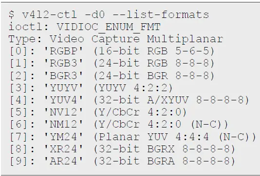
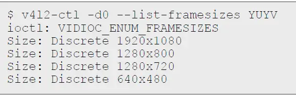
- List the supported pixel formats:

- Capture the camera data and save them to a file using the “v4l2-ctl” command. The supported pixel formats and resolutions are listed above. Here is an example to capture the 1280×800 YUYV camera data:

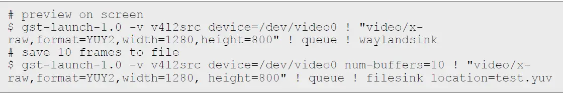
- Capture the camera data, preview them on screen or save them to a file using the “gstreamer” commands:


Note about the source code in the document
Example code shown in this document has the following copyright and BSD-3-Clause license:
Copyright 2023 NXP Redistribution and use in source and binary forms, with or without modification, are permitted provided that the following conditions are met:
- Redistributions of source code must retain the above copyright notice, this list of conditions and the following disclaimer.
- Redistributions in binary form must reproduce the above copyright notice, this list of conditions and the following disclaimer in the documentation and/or other materials must be provided with the distribution.
- Neither the name of the copyright holder nor the names of its contributors may be used to endorse or promote products derived from this software without specific prior written permission.
THIS SOFTWARE IS PROVIDED BY THE COPYRIGHT HOLDERS AND CONTRIBUTORS “AS IS” AND ANY EXPRESS OR IMPLIED WARRANTIES, INCLUDING, BUT NOT LIMITED TO, THE IMPLIED WARRANTIES OF MERCHANTABILITY AND FITNESS FOR A PARTICULAR PURPOSE ARE DISCLAIMED. IN NO EVENT SHALL THE COPYRIGHT HOLDER OR CONTRIBUTORS BE LIABLE FOR ANY DIRECT, INDIRECT, INCIDENTAL, SPECIAL, EXEMPLARY, OR CONSEQUENTIAL DAMAGES (INCLUDING, BUT NOT LIMITED TO, PROCUREMENT OF SUBSTITUTE GOODS OR SERVICES; LOSS OF USE, DATA, OR PROFITS; OR BUSINESS INTERRUPTION) HOWEVER CAUSED AND ON ANY THEORY OF LIABILITY, WHETHER IN CONTRACT, STRICT LIABILITY, OR TORT (INCLUDING NEGLIGENCE OR OTHERWISE) ARISING IN ANY WAY OUT OF THE USE OF THIS SOFTWARE, EVEN IF ADVISED OF THE POSSIBILITY OF SUCH DAMAGE.
8 Legal information
Definitions
Draft — A draft status on a document indicates that the content is still under internal review and subject to formal approval, which may result in modifications or additions. NXP Semiconductors does not give any representations or warranties as to the accuracy or completeness of information included in a draft version of a document and shall have no liability for the consequences of use of such information.
Disclaimers
Limited warranty and liability — Information in this document is believed to be accurate and reliable. However, NXP Semiconductors does not give any representations or warranties, expressed or implied, as to the accuracy or completeness of such information and shall have no liability for the consequences of use of such information. NXP Semiconductors takes no responsibility for the content in this document if provided by an information source outside of NXP Semiconductors.
In no event shall NXP Semiconductors be liable for any indirect, incidental, punitive, special or consequential damages (including – without limitation -lost profits, lost savings, business interruption, costs related to the removal or replacement of any products or rework charges) whether or not such damages are based on tort (including negligence), warranty, breach of contract or any other legal theory.
Notwithstanding any damages that customer might incur for any reason whatsoever, NXP Semiconductors’ aggregate and cumulative liability towards customer for the products described herein shall be limited in accordance with the Terms and conditions of commercial sale of NXP Semiconductors.
Right to make changes — NXP Semiconductors reserves the right to make changes to information published in this document, including without limitation specifications and product descriptions, at any time and without notice. This document supersedes and replaces all information supplied prior to the publication hereof.
Suitability for use — NXP Semiconductors products are not designed, authorized or warranted to be suitable for use in life support, life-critical or safety-critical systems or equipment, nor in applications where failure or malfunction of an NXP Semiconductors product can reasonably be expected to result in personal injury, death or severe property or environmental damage. NXP Semiconductors and its suppliers accept no liability for inclusion and/or use of NXP Semiconductors products in such equipment or applications and therefore such inclusion and/or use is at the customer’s own risk.
Applications — Applications that are described herein for any of these products are for illustrative purposes only. NXP Semiconductors makes no representation or warranty that such applications will be suitable for the specified use without further testing or modification.
Customers are responsible for the design and operation of their applications and products using NXP Semiconductors products, and NXP Semiconductors accepts no liability for any assistance with applications or customer product design. It is customer’s sole responsibility to determine whether the NXP Semiconductors product is suitable and fit for the customer’s applications and products planned, as well as for the planned application and use of customer’s third party customer(s). Customers should provide appropriate design and operating safeguards to minimize the risks associated with their applications and products.
NXP Semiconductors does not accept any liability related to any default, damage, costs or problem which is based on any weakness or default in the customer’s applications or products, or the application or use by customer’s third party customer(s). Customer is responsible for doing all necessary testing for the customer’s applications and products using NXP Semiconductors products in order to avoid a default of the applications and the products or of the application or use by customer’s third party customer(s). NXP does not accept any liability in this respect.
Terms and conditions of commercial sale — NXP Semiconductors products are sold subject to the general terms and conditions of commercial sale, as published at http://www.nxp.com/profile/terms, unless otherwise agreed in a valid written individual agreement. In case an individual agreement is concluded only the terms and conditions of the respective agreement shall apply. NXP Semiconductors hereby expressly objects to applying the customer’s general terms and conditions with regard to the purchase of NXP Semiconductors products by customer.
Export control — This document as well as the item(s) described herein may be subject to export control regulations. Export might require a prior authorization from competent authorities.
Suitability for use in non-automotive qualified products — Unless
this data sheet expressly states that this specific NXP Semiconductors product is automotive qualified, the product is not suitable for automotive use. It is neither qualified nor tested in accordance with automotive testing or application requirements. NXP Semiconductors accepts no liability for inclusion and/or use of non-automotive qualified products in automotive equipment or applications.
In the event that customer uses the product for design-in and use in automotive applications to automotive specifications and standards, customer (a) shall use the product without NXP Semiconductors’ warranty of the product for such automotive applications, use and specifications, and (b) whenever customer uses the product for automotive applications beyond NXP Semiconductors’ specifications such use shall be solely at customer’s own risk, and (c) customer fully indemnifies NXP Semiconductors for any liability, damages or failed product claims resulting from customer design and use of the product for automotive applications beyond NXP Semiconductors’ standard warranty and NXP Semiconductors’ product specifications.
Translations — A non-English (translated) version of a document, including the legal information in that document, is for reference only. The English version shall prevail in case of any discrepancy between the translated and English versions.
Security — Customer understands that all NXP products may be subject to unidentified vulnerabilities or may support established security standards or specifications with known limitations. Customer is responsible for the design and operation of its applications and products throughout their lifecycles to reduce the effect of these vulnerabilities on customer’s applications and products. Customer’s responsibility also extends to other open and/or proprietary technologies supported by NXP products for use in customer’s applications. NXP accepts no liability for any vulnerability. Customer should regularly check security updates from NXP and follow up appropriately.
Customer shall select products with security features that best meet rules, regulations, and standards of the intended application and make the ultimate design decisions regarding its products and is solely responsible for compliance with all legal, regulatory, and security related requirements concerning its products, regardless of any information or support that may be provided by NXP.
NXP has a Product Security Incident Response Team (PSIRT) (reachable at [email protected]) that manages the investigation, reporting, and solution release to security vulnerabilities of NXP products.
NXP B.V. – NXP B.V. is not an operating company and it does not distribute or sell products.
Trademarks
Notice: All referenced brands, product names, service names, and trademarks are the property of their respective owners.
NXP — wordmark and logo are trademarks of NXP B.V.
i.MX — is a trademark of NXP B.V.
Please be aware that important notices concerning this document and the product(s) described herein, have been included in section ‘Legal information’.
References
 Automotive, IoT & Industrial Solutions | NXP Semiconductors
-
Our Terms And Conditions Of Commercial Sale | NXP Semiconductors
 GitHub - nxp-imx/linux-imx: i.MX Linux kernel
-
ap1302_binaries/README.md at main · ONSemiconductor/ap1302_binaries · GitHub
-
ap1302_binaries/NXP_i.MX93 at main · ONSemiconductor/ap1302_binaries · GitHub


