
NXP UM11559 Socket Board
Introduction
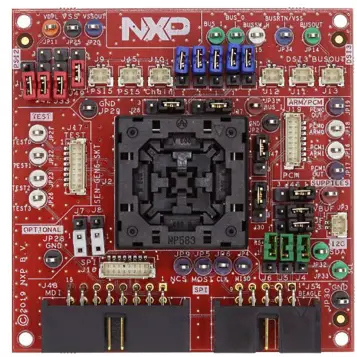
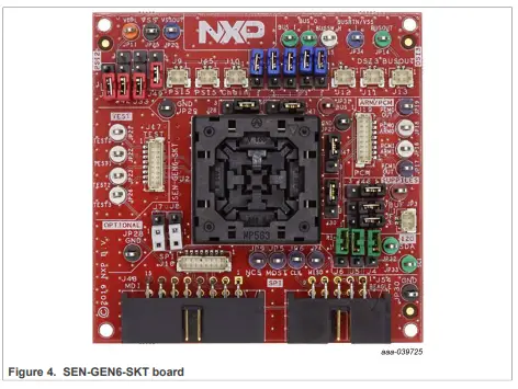
SEN-GEN6-SKT Kit
The SEN-GEN6-SKT board is a socket kit designed to evaluate the FXLS9xxxx, and FXPS7xxxx sensors. The board supports different communication configurations such as SPI, I²C, DSI3 or PSI5. Before inserting a device into the socket, make sure you have properly configured the board to support the desired protocol. This user manual describes the different options
Definitions
Draft status on a document indicates that the content is still under internal review and subject to formal approval, which may result in modifications or additions. NXP Semiconductors does not give any representations or warranties as to the accuracy or completeness of information included in a draft version of a document and shall have no liability for the consequences of use of such information.
Kit contents
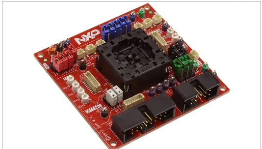
- One automotive Sensor Socket board (SEN-GEN6-SKT)
- Four red jumpers
- Two white jumpers
- Five blue jumpers
- Three green jumpers
- Seven purple jumpers
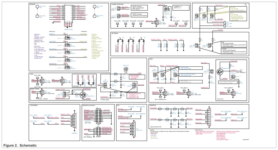
Schematic
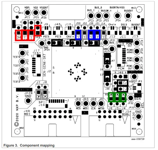
Component mapping
Order an FXLSxxxx sensor
| Device | Variation | Protocol |
| FXLS90322 | XY – MM | SPI, DSI3 |
| FXLS90422 | XZ – MM | SPI, DSI3 |
| FXLS90333 | XY – HH | SPI, DSI3 |
| FXLS90433 | XZ – HH | SPI, DSI3 |
| FXLS93322 | XY – MM | PSI5 |
| FXLS93422 | XZ – MM | PSI5 |
| FXLS93333 | XY – HH | PSI5 |
| FXLS93433 | XZ – HH | PSI5 |
| FXLS90220 | X – M | SPI, DSI3 |
| FXLS90230 | X – H | SPI, DSI3 |
| FXLS90120 | Z – M | SPI, DSI3 |
| FXLS90130 | Z – H | SPI, DSI3 |
| FXLS93220 | X – M | PSI5 |
| FXLS93230 | X – H | PSI5 |
| FXLS93120 | Z – M | PSI5 |
| FXLS93130 | Z – H | PSI5 |
| FXPS7115D4 | 40 – 115 kPa | SPI |
| FSPS7115DS4T1 | 40 – 115 kPa | SPI |
| FSPS7115DI4T1 | 40 – 115 kPa | I2C |
| FXPS7140D4 | 40 – 140 kPa | DSI3 |
| FXPS7140P4 | 50 – 126 kPa | PSI5 |
| FXPS7165DS4T1 | 60 – 165 kPa | SPI |
| FXPS7165DI4T1 | 60 – 165 kPa | I2C |
| FXPS7250DS4T1 | 20 – 250 kPa | SPI |
| FXPS7250DI4T1 | 20 – 250 kPa | I2C |
| FXPS7400DS4T1 | 20 – 400 kPa | SPI |
| FXPS7400DI4T1 | 20 – 400 kPa | I2C |
| FXPS7550DS4T1 | 20 – 550 kPa | SPI |
| FXPS7550DI4T1 | 20 – 550 kPa | I2C |
Order a kit
Configure the board
The board supports the FXLS9xxxx, and FXPS7xxxx sensor families. For easier board configuration, the jumpers have been colored per category/protocol. They are listed below:
- Sensor compatibility or power supply related: black
- I²C: green
- DSI3: blue
- PSI5: red
- SPI: N/A
By default, the board is configured for FXLS9xxxx devices in SPI mode. However, the configuration can easily be modified using the jumpers. By default, most jumpers are floating. Floating means they are attached to their proper connector but remain unconnected. The reference to “DNP” means “Do not populate”, meaning it can be removed or unshorted.
FXLS9xxxx (default) or FXPS7xxxx
Table 2 identifies the proper jumper settings for family compatibility
Family compatibility
| Jumper reference | Jumper position | |
| FXLS9xxxx compatibility | FXPS7xxxx compatibility | |
| J28 | 1-2 | 2-3 |
| J30 | 1-2 | 2-3 |
| J37 | 1-2 | 2-3 |
| J47 | 1-2 | 2-3 |
| J55 | 1-2 | 2-3 |
SPI (default)
By default, the board is configured to support SPI communication. NXP recommends configuring J1, J3, and J36 as non-floating potentials on the sensor supply pins. Refer to the product data sheet. Ensure that J4, J5, and J6 are not populated (pull-up resistors). J7 and J8 must remaining floating for SPI mode.
SPI mode jumper configuration
| Jumper reference | Jumper position | Description |
| J3 | 1-2 | Connect BUS_I/VCC to VBUF_VCCIO |
| J1 | (1-2) | Connect BUS_I/VCC to BUS_O (optional) |
| J36 | (1-2) | Connect BUS_I/VCC to IDATA (Optional) |
| J46 | 2-3 | VCC with 1 μF capacitor |
| J4 | 1 or DNP | Floating |
| J5 | 1 or DNP | Floating |
| J6 | 1 or DNP | Floating |
| J7 | 1 or DNP | Floating |
| J8 | 1 or DNP | Floating |
I²C
In order to configure I²C mode, begin with the SPI mode configuration and add pull-up resistors on SDA, SCL, and the CS pins. If the I²C lines are already driven by the MCU (shared pull-up), NXP recommends leaving J4 and J6 unpopulated.
I²C mode jumper configuration
| Jumper reference | Jumper position | Description |
| J3 | 1-2 | Connect BUS_I/VCC to VBUF_VCCIO |
| J1 | (1-2) | Connect BUS_I/VCC to BUS_O (optional) |
| Jumper reference | Jumper position | Description |
| J36 | (1-2) | Connect BUS_I/VCC to IDATA (Optional) |
| J46 | 2-3 | VCC with 1 μF capacitor |
| J4 | 1-2 | Add pull-up resistor on I²C SLC signal |
| J5 | 1-2 | Add pull-up resistor on I²C SDA signal |
| J6 | 1-2 | Add pull-up resistor on SS_B signal |
| J7 | 1 or DNP | Floating |
| J8 | 1 or DNP | Floating |
DSI3
The communication interface between an ECU device (such as MC33SA0528AC) and the sensor device in DSI3 mode is established via a DSI3 compatible two-wire interface, with parallel or serial (daisy-chain) connections to the satellite modules
DSI3 mode jumper configuration
| Jumper reference | Jumper position | Description |
| J1 | 1 or DNP | Floating |
| J3 | 1 or DNP | Floating |
| J46 | 2-3 | BUS_I/VCC with 0.47 μF capacitor |
| J36 | 1-2 | Connect BUS_I/VCC to IDATA |
| J50 | 1-2 | Add 100 pF cap between BUS_O and BUSRTN |
| J51 | 1-2 | Add 200 pF cap between BUS_I/VSS and BUSRTN |
| J52 | (1-2) | Optional EMC filter |
| J8 | 1 or DNP | Floating |
PSI5
The communication interface between an ECU device and this sensor device in PSI5 mode is established via a PSI5 compatible two-wire interface, with universal or daisychain connections to the satellite modules
PSI5 mode jumper configuration
| Jumper reference | Jumper position | Description |
| J1 | 1 or DNP | Floating |
| J3 | 1 or DNP | Floating |
| J46 | 2-3 | BUS_I/VCC with 0.47 μF capacitor |
| J42 | 1-2 | Filtering (FXLS9xxxx) |
| 2-3 | Filtering (FXPS7xxxx) | |
| J34 | 1-2 | Connect the filter to IDATA |
| Jumper reference | Jumper position | Description |
| J33 | 1-2 | Connect the filter to BUS_I/VCC (FXLS9xxxx only) |
| 2-3 | Connect the filter to BUS_I/VCC (FXLS9xxxx only) | |
| J49 | 1-2 or 2-3 | If using PSI5 daisy chain |
Insert the sensor into the socket
illustrates the proper way to insert the sensor into the socket. For proper connection, align the circle on the IC to the arrowhead (identified in yellow in Figure 5) on the mounting socket.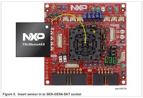
Connect the board to a compatible ECU
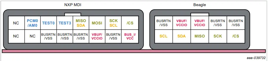
The SEN-SPI-BOX has two dedicated interfaces suitable for SPI and I²C communications, an MDI connector and a Beagle connector. The NXP MDI connector supports the SEN-SPI-BOX kit. The Beagle connector is an industrial standard and may be coupled to any Beagle compatible analyzer. For DSI3 and PSI5 support, the SEN-SPI-BOX can be used with a dedicated NXP adapter (SEN-DSI3-ADAPTER and SEN-PSI5-ADAPTER). Refer to Section 2.5.1 for board connections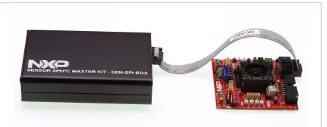
NXP MDI and Beagle
illustrates the MDI and Beagle connectors while Figure 8 identifies the individual connectors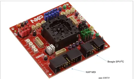
SPI
Connect the SEN-GEN6-SKT board to any MCU with SPI compatibility using the 4-pin SPI signals and a power supply.
VCC must not exceed 5.25 V.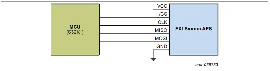
SPI connector reference
| Signal name | Connector reference | Description |
| VCC | JP31 | Power supply |
| GND | JP29 | Ground |
| SS_B | JP9 | Chip select |
| SCLK | JP6 | Serial Clock |
| MISO | JP4 | MCU In Sensor out |
| MOSI | JP5 | MCU out Sensor in |
| SPI | J16 | 4-pin SPI connector |
| NXP MDI | J48 | General-purpose connector |
| Beagle | J54 | General-purpose connector |
I²C
Connect the SEN-GEN6-SKT board to any I²C MCU board using the two-pin I²C signals and a power supply.
VCC must not exceed 5.25 V.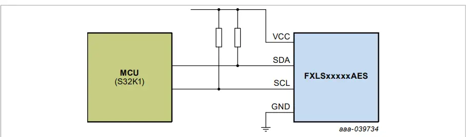
I²C connector referenceDSI3
The DSI3 protocol, an automotive protocol, provides power supply and bidirectional communication using only two wires. This protocol is suitable for all satellite-based applications (such as airbag) requiring safety and EMC robustness
| Signal name | Connector reference | Description |
| VCC | JP31 | Power supply |
| GND | JP29 | Ground |
| SDA | JP32 | I²C Serial Data |
| SCL | JP33 | I²C Serial Clock |
| I²C | J16 | two-pin I²C connector |
| NXP MDI | J48 | General-purpose connector |
| Beagle | J54 | General-purpose connector |
DSI3 connector reference
| Signal name | Connector reference | Description | Mode |
| BUSIN | JP12 | DSI3 Bus In | Discovery mode / Parallel mode |
| BUSRTN | JP34 | DSI3 bus return | |
| DSI3 | J11 | two-pin DSI3 connector | |
| BUS_O | JP13 | Daisy chain out | Daisy chain mode |
| BUSRTN | JP34 | DSI3 bus return | |
| DSI3_Chain | J12 | two-pin DSI3 daisy chain connector | |
| BUSOUT | JP14 | Daisy chain out | Daisy chain mode (FXPS7xxxx only) |
| BUSRTN | JP34 | DSI3 bus return | |
| DSI3_Chain | J13 | two-pin DSI3 daisy chain connector |
DSI3 parallel or discovery mode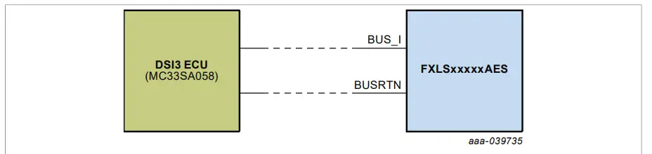 DSI3 daisy chain
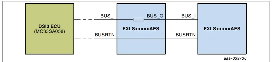 DSI3 daisy chain mode (FXPS7xxxx only)
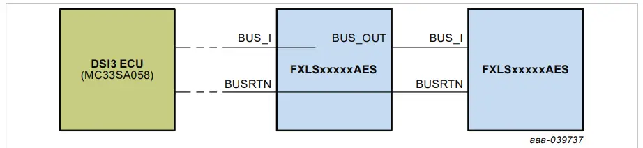
PSI5
The PSI protocol, an automotive protocol, provides power supply and bidirectional communication using only two wires. This protocol is suitable for all satellite-based applications.
PSI5 connector reference
| Signal name | Connector reference | Description | Mode |
| VDPL | JP11 | PSI5 BUS IN | Universal mode / Parallel mode |
| VSS | JP25 | PSI5 VSS | |
| PSI5 | J9, J45 | two-pin PSI5 connector | |
| VDPL | JP11 | PSI5 BUS IN | Daisy chain mode |
| VSSOUT | JP20 | PSI5 VSS daisy chain | |
| PSI5_Chain | J10 | two-pin PSI5 daisy chain out |
PSI5 parallel or universal mode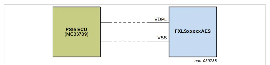
PSI5 daisy chain mode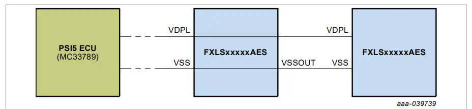
Disclaimers
Limited warranty and liability
Information in this document is believed to be accurate and reliable. However, NXP Semiconductors does not give any representations or warranties, expressed or implied, as to the accuracy or completeness of such information and shall have no liability for the consequences of use of such information. NXP Semiconductors takes no responsibility for the content in this document if provided by an information source outside of NXP Semiconductors. In no event shall NXPSemiconductors be liable for any indirect, incidental, punitive, special or consequential damages (including – without limitation – lost profits, lost savings, business interruption, costs related to the removal or replacement of any products or rework charges) whether or not such damages are based on tort (including negligence), warranty, breach of contract or any other legal theory. Notwithstanding any damages that the customer might incur for any reason whatsoever, NXP Semiconductor’s aggregate and cumulative liability towards the customer for the products described herein shall be limited in accordance with the Terms and conditions of the commercial sale of NXPSemiconductors.
Right to make changes
NXP Semiconductors reserves the right to make changes to information published in this document, including without limitation specifications and product descriptions, at any time and without notice. This document supersedes and replaces all information supplied prior to the publication hereof.
Applications
Applications that are described herein for any of these products are for illustrative purposes only. NXP Semiconductors makes no representation or warranty that such applications will be suitable for the specified use without further testing or modification. Customers are responsible for the design and operation of their applications and products using NXP Semiconductors products, and NXP Semiconductors accepts no liability for any assistance with applications or customer product design. It is the customer’s sole responsibility to determine whether the NXPSemiconductors product is suitable and fit for the customer’s applications and products planned, as well as for the planned application and use of customer’s third party customer(s). Customers should provide appropriate design and operating safeguards to minimize the risks associated with their applications and products. NXP Semiconductors does not accept any liability related to any default, damage, costs or problem which is based on any weakness or default in the customer’s applications or products, or the application or use by the customer’s third party customer(s). The customer is responsible for doing all necessary testing for the customer’s applications and products using NXP Semiconductors products in order to avoid a default of the applications and the products or of the application or use by the customer’s third party customer(s). NXP does not accept any liability in this respect.
Export control
This document as well as the item(s) described herein may be subject to export control regulations. Export might require a prior authorization from competent authorities.
Evaluation products
This product is provided on an “as is” and “with all faults” basis for evaluation purposes only. NXP Semiconductors, its affiliates, and their suppliers expressly disclaim all warranties, whether express implied or statutory, including but not limited to the implied warranties of non-infringement, merchantability, and fitness for a particular purpose. The entire risk as to the quality, or arising out of the use or performance, of this product, remains with the customer. In no event shall NXP Semiconductors, its affiliates or their suppliers be liable to the customer for any special, indirect, consequential, punitive or incidental damages (including without limitation damages for loss of business, business interruption, loss of use, loss of data or information, and the like) arising out the use of or inability to use the product, whether or not based on tort (including negligence), strict liability, breach of contract, breach of warranty or any other theory, even if advised of the possibility of such damages. Notwithstanding any damages that the customer might incur for any reason whatsoever (including without limitation, all damages referenced above and all direct or general damages),the entire liability of NXP Semiconductors, its affiliates and their suppliers and customer’s exclusive remedy for all of the foregoing shall be limited to actual damages incurred by customer based on reasonable reliance up tothe greater of the amount actually paid by the customer for the product or five dollars (US$5.00). The foregoing limitations, exclusions and disclaimers shall apply to the maximum extent permitted by applicable law, even if any remedy fails of its essential purpose.
Translations
A non-English (translated) version of a document is for reference only. The English version shall prevail in case of any discrepancy between the translated and English version
Security
The customer understands that all NXP products may be subject to unidentified or documented vulnerabilities. Customer is responsible for the design and operation of its applications and products throughout their lifecycles to reduce the effect of these vulnerabilities on customer applications and products. The customer’s responsibility also extends to other open and/or proprietary technologies supported by NXP products for use in customers’ applications. NXP accepts no liability for any vulnerability. Customers should regularly check security updates from NXP and follow up appropriately. Customer shall select products with security features that best meet rules, regulations, and standards of the intended application and make the ultimate design decisions regarding its products and is solely responsible for compliance with all legal, regulatory, and security-related requirements concerning its products, regardless of any information or support that may be provided by NXP. NXP has a Product Security Incident Response Tea (PSIRT) (reachable at [email protected]) that manages the investigation, reporting, and solution release to security vulnerabilities of NXP products.
Suitability for use in automotive applications
This NXP product has been qualified for use in automotive applications. It has been developed in accordance with ISO 26262, and has been ASIL-classified accordingly. If this product is used by the customer in the development of, or for incorporation into, products or services (a) used in safety-critical applications or (b) in which failure could lead to death, personal injury, or severe physical or environmental damage (such products and services hereinafter referred to as “Critical Applications”), then customer makes the ultimate design decisions regarding its products and is solely responsible for compliance with all legal, regulatory, safety, and security-related requirements concerning its products, regardless of any information or support that may be provided by NXP. As such, the customer assumes all risk related to use of any product in Critical Applications and NXP and its suppliers shall not be liable for any such use by the customer. Accordingly, the customer will indemnify and hold NXP harmless from any claims, liabilities, damages, and associated costs and expenses (including attorneys’ fees) that NXP may incur related to the customer’s incorporation of any product in a Critical Application.


