MCC Marine Chiller Control Display Instruction Manual
Introduction
The Marine Chiller Control, identified in this document as MCC, can be used as a standalone or staged chiller controller to regulate loop water temperature in tempered water systems. MCC also provides a level of protection against system damages caused by high or low refrigerant pressures, water flow problems, freezing of the compressor, and low line voltage. The MCC can be used to control directly connected compressors, VFD’s, reversing valves, electric heaters and system pumps.
Wiring
Controls must be connected as shown in the wiring diagram contained in this manual. High limit, freeze and return sensors must be the appropriate Microair sensor listed in the diagram. Switch inputs are dry contact only and must not have any outside connections to voltage or current sources. External contactors must be used for water pumps over ½ HP, compressors over 2 HP, and for electric heaters.
Stand Alone Operation
Power Application
When power is first applied, the display will show the firmware revision for 2 seconds and then go blank if the mode switch is in the off position. Change the mode switch to select heating or cooling.
Reversing Valve Operation
If a cycle is called within 75 seconds of a power restore or termination of a cycle, the reversing valve will toggle to equalize system pressures. This toggle will not occur if electric heat is enabled. The reversing valve will remain active when the compressor is active in heat mode.
Water Pump Operation
The circulating water pump (CWP) output will remain in operation whenever the mode switch selects heat or cool. The seawater pump (SWP) output will cycle with the compressor or run continuously depending on the “CON, dc” program parameter setting. See the program parameters section in this manual for more information.
Operating Modes
When heat or cool is selected on the mode switch, the display will alternate between showing “SUP” (supply or outlet temperature measured by the freeze sensor), followed by the temperature and “rtr” (return or inlet temperature) followed by the temperature. If the water temperature deviation is 2° or greater from the set point, then the MCC will start a cycle. The compressor will start and continue to operate until the loop return temperature reaches set point.
Error Messages
| Message | Definition |
| FLO | Flow switch has been open for over 10 seconds during the cycle. Operation will resume once the switch closes again. |
| HIP | The high refrigerant pressure switch was open. Operation will resume once the switch closes again. Four faults occurring in a cooling cycle will create a lockout. Lockouts can be cleared by switching the mode switch to off then back to the desired mode. |
| LoP | The low refrigerant pressure switch was open for more than 10 minutes. Operation will resume once the switch closes again. Four faults occurring in a cooling cycle will create a lockout. Lockouts can be cleared by switching the mode switch to off then back to the desired mode. |
| HIL | A water temperature of over 125°F (51.7°C) was measured at the high limit sensor with an electric heat enabled. The system will stop operation until the water temperature drops below 110°F (43.3°C) |
| HSC | A malfunction was detected in the high limit sensor. Repair the malfunction to resume operation. |
| FSN | A malfunction was detected in the freeze sensor. Repair the malfunction to resume operation. |
| SEN | A malfunction was detected in the return sensor. Repair the malfunction to resume operation. |
| FrE | A freezing temperature less than 38°F (3.3°C) was detected. Operation will resume once the water temperature is above 49°F (9.4°C). |
| LAC | A low AC line voltage condition was detected and the compressor was shut down. Line voltage must be below 85 VAC (120 volt units) or 170 VAC (208-240 VAC units) for 10 minutes for this fault to occur. Operation will resume once line voltage is above 100VAC (120 VAC systems) or 200 VAC (208-240 VAC systems). |
| PE | Program error. Control must be replaced or returned for servicing. |
Program Parameters
Certain operational attributes can be changed to configure the control. Press the
“Select” button on the control to advance from one parameter to the next parameter. Press and hold the “set” button to decrement the parameter. Release the “set” button, then press and hold the button again to increment a parameter. The control will exit the program mode after 15 seconds without a button press
| Parameter | Definition | Range |
| CSP | Cooling set point: The control will operate the compressor from 2° above this temperature or higher and continue until the temperature is equal or below this temperature. | 40°F to 58°F (4.4°C to 14.4) |
| HSP | Heating set point: The control will operate the compressor or electric heater from 2° below this temperature or lower and continue until the temperature is equal or above this temperature. | 95°F to 120°F (35°C to 48.9°C) |
| dI | Staging delay: The amount of time the control must wait after a cycle completes or a power restoration before starting the compressor. | 10 to 200 seconds |
| °F or °C | Fahrenheit or Celsius selection | °F or °C |
| rc or EH | Reverse cycle or electric heat selection: Select EH if there is an electric heater contactor connected to the EL. Heater dry contact relay. | rc or EH |
| dc or con | Cycled or continuous sea pump operation: When set for dc, the sea pump cycles with the compressor. | dc or con |
| LPE or LPd | Low pressure enable or low pressure disable: When set for LPd, the low refrigerant pressure switch is ignored. | LPE or LPd |
| AC | AC line voltage: This parameter displays the AC line voltage measured by the control. Adjustment is possible but should only be performed by knowledgeable service technicians. Improper adjustment will result in false detection of low voltage conditions. | Dependent on line voltage. |
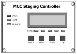
MCC Staging Controller
Introduction
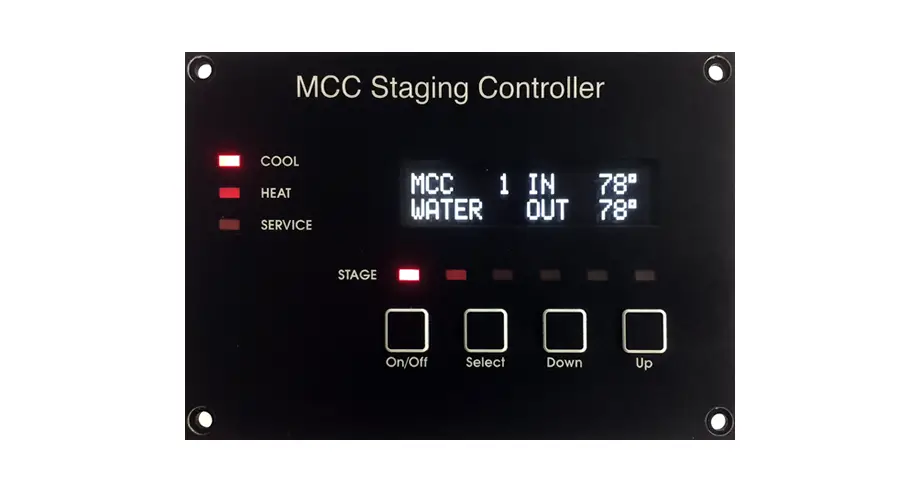
The MCC staging controller is a multi-stage controller capable of handling up to 6 chillers and two displays. The MCC staging controller system consists of a circuit board that connects to one or more MCC controls and a display. The display panel shows the active state of each MCC controlled compressor or heater connected, inlet and outlet temperatures for each stage, and the run time hours for each stage. Each compressor in the system is considered a stage.
Operating the display
When the system is off the display reads “SYSTEM OFF”. Press and release the power button once to turn the system on. Use the SELECT BUTTON to obtain heating or cooling as required. Stages called for are indicated by the stage LED. The display back lighting is automatically activated when any button is pressed. Not pressing any buttons for sixty-seconds automatically turns OFF the back lighting.
When the system is active in heat or cool, the display will scroll information showing water in and out for each stage and the run time hours for the stage being displayed. If the optional refrigerant pressure transducers are installed, the pressure readings will also be displayed with each stage. A stage that has been bypassed will also display as “Stage x Bypassed”. If the optional water pressure sensors are installed, the pressure information will display after the last stage data is displayed.
Display scrolling can be temporarily stopped by pressing and releasing either the up or down button once. The display will stop scrolling at the function where it’s stopped. To move forward through the scroll functions press and release the up button. This moves the display forward one scroll item. To move backward through the scroll functions press and release the down button. This moves the display backward one scroll function. Exit the display scroll function by simultaneously pressing the up and down buttons. The display will also automatically resume normal scroll functions if no buttons are pressed for sixty–seconds (60).
MCC Staging Controller Programming
Caution! Programming should only be performed by qualified service technicians, consult your Microair Air representative before attempting to make any program changes.
Entering the program mode
There are nine (9) programmable parameters. To enter the program mode turn the system off. With the word OFF visible in the display press and release the Select, Up, Down and Select buttons in the sequence described. Once in the program mode the first item, “BYPASSED STAGES”, appears in the display. Press and release the select button to scroll through the parameters as shown in the table below.
| Parameter | Default Setting | Range |
| BYPASSED STAGES | None | 1-6 |
| HEATING STAGES | All | 1-6 |
| HEATING SET POINT | 104°F | 95°F TO 120°F |
| COOLING SET POINT | 45°F | 42°F TO 58°F |
| HYSTERESIS | 2°F | 1°F TO 3°F |
| DIFFERENTIAL | 2°F | 1°F TO 3°F |
| STAGING DELAY | 60 SECONDS | 15 TO 200 SECONDS IN 5 SEC. INCREMENTS |
| SEA WATER PUMP | CONTINUOUS | CYCLE OR CONTINUOUS |
| SYSTEM UNITS | FAHRENHEIT | CELSIUS OR FAHRENHEIT |
| GANG STAGING | None | 1 TO NUMBER OF STAGES |
| ZERO WATER TRANSDUCERS | PRESS AND RELEASE THE UP BUTTON | |
| AC TRIP POINT | OFF | OFF, 70 TO 100, 170 TO 200 |
| SAVE SETTINGS AS DEFAULT | PRESS AND RELEASE THE UP BUTTON | |
| RECALL DEFAULT SETTINGS | PRESS AND RELEASE THE UP BUTTON | |
| VIEW HISTORY LOG | PRESS AND RELEASE THE DOWN BUTTON | |
Bypassed Stages:
The display will show numbers 1 to 6, six dashes, or a combination of numbers and dashes for each of the possible stages that could be connected. Press and release the down button to advance through each of the six stages. Inactive stages will show as a number and active stages will show as a dash (“-“). Once the desired stage is selected, press and release the up button to change the stage selection.
Heating Stages
Not all stages are equally equipped in all installations. This parameter allows enabling only stages capable of providing heat during heat mode. The factory setting for all heaters is disabled. Stages are selected in the same manner as the “bypasses stages” parameter. Enable the heater by selecting the stage and change the dash “-“to a number.
Heating set point
Change this parameter to set the return loop heating temperature managed by the MCC staging controller.
Cooling set point
Change this parameter to set the return loop cooling temperature managed by the MCC staging controller.
Hysteresis
The number of active stages is managed by determining the return water temperature deviation from set point. For each hysteresis interval deviation the return water moves toward set point, an additional stage is turned off until set point is reached. Select the number of degrees deviation to turn off stages with this parameter.
Differential
The number of active stages is managed by determining the return water temperature deviation from set point. For each differential interval deviation from set point, an additional stage is added until all stages are active. Select the number of degrees deviation to start stages with this parameter.
Staging delay
This time sets the minimum start time between compressors.
Sea Water pump
This Parameter selects between continuous and cycled (if any compressors are
operating) operation of the sea water pump.
System units
Select between Celsius and Fahrenheit temperature units
Gang staging
In some multistage systems it may be desirable for more than one stage to operate at a differential point. Access this parameter using the same method used to access bypassed stages. The first differential point is in the left. Select from 1 to 3 stages to operate with the first differential. Press the up button to move the selection to the second position and use the up button to change the selection for the second differential point.
Zero water transducers
If the off pressure of the water transducers does not read zero, press the up button.
AC trip point
Set this parameter to the desired shutdown voltage to protect compressors from extended running with marginal AC power. The MCC staging controller will generate a Low AC fault if any stage reports below this set voltage for more than 10 minutes.
Save settings as default
Since most chilled water installations are not the same, standard factory default settings are not applicable to all systems. New defaults have to be programmed according to system requirements. Once the new requirements are programmed, press and release the Mode Button until “SAVE SETTINGS AS DEFAULT” appears in the display. Press the Up Button to save the current settings as the new default settings.
Recall default settings
The new defaults can be recalled at any time by entering the program mode and selecting this parameter and pressing the up button.
View History Log
The history log displays the last 16 faults from oldest (16) to newest (1). Press the up or down buttons to scroll through the entries.
MCC Control Programming
Only two program parameters are available on the connected MCC controllers with the MCC Staging Controller connected.
EH / rc
Press the select button once on the MCC controller to view the first parameter. Use the SET button on the MCC controller to change the value from EH (electric heat) to rc (reverse cycle) to select the correct heat mode. If there is no heat mode available, be sure to disable the heat for this stage in the MCC staging controller parameter menu.
LPd / LPE
Press the select button a second time on the MCC controller to view the second parameter. If the stage is equipped with a low refrigerant pressure switch, set the value to LPE (low pressure enable) otherwise set the value to LPd (low pressure disable) using the set button.
Staging Controller Fault Protocol
The staging controller software includes a fault protocol designed to protect the system while, at the same time, allowing the operational stages to continue cooling or heating. The table below lists the fault and the action taken when the fault occurs
| Fault Protocol | ||
| Fault | Stage | Action |
| Freeze Sensor | Any Stage | Compressor shut-Down |
| Flow Switches 1 – 6 | Stages 1 thru 6 | Compressor Shut-Down |
| High Pressure Switch | Any Stage | Compressor Shut-Down |
| Low Pressure Switch | Any Stage | Compressor Shut-Down |
| High Limit Reverse Cycle Temperature | Any Stage | Compressor Shut-Down Lockout after 4 Failures |
| High Limit Electric Heat Temperature | Any Stage | System Shut-Down |
| Freeze Limit | Any Stage | Compressor Shut-Down |
| Return Sensor | 1 Required Any Stage | System Shut-Down Lockout after 4 failures |
| Stage 1 Not Responding | Pumps Connected to Stage One | System Shut-Down |
| Stages Not Responding | Stages 2 Thru 6 | Compressor Shut-Down |
Additional Fault Troubleshooting Information
The HIGH LIMIT SENSOR and RETURN WATER SENSOR are connected to stage one. Because the system cannot operate properly without these sensors, four consecutive high limit failures or four consecutive return sensor failures will cause the system to shut down and lockout.
Since all the systems critical components are connected to stage one, the entire system is shut down when stage on fails to communicate with the staging controller. Stage one compressor can be by-passed, however, stage one (1) will continue to operate the systems critical components.
The seawater pump, chill water pump, inlet water and outlet water sensor must be connected to stage one DDC. Stage one (1) is defined by plugging the assigned DDC module into number one location on the DDC interface board.
Fatal faults are defined as four (4) consecutive failures on a stage causing that stage to be locked out. The service light will flash; the display will indicate the fault and lockout condition. The stage can be cleared and restarted by pressing the SELECT BUTTON. Accumulated stage faults are automatically cleared, before fourth fault, if the stage operates four hours (4) without any new faults.
High Freon pressure lockout faults are ignored in the heat mode. The compressor will shut down, the stage delay timer will start when the fault clears and the compressor will start after the stage delay times out.
Low Freon pressure fault has a ten (10) minute delay allowing the compressor to come up to normal operating pressures.
The water outlet temperature is acquired via the freeze-stat sensors.
When a stage is by-passed the staging temperature and staging delay are automatically adjusted so there is neither a timing nor temperature gap. The next stage in line assumes the by-passed stage’s timing and staging temperature
The stage controller is factory configured for standard reverse cycle heating. When installing electric heaters the reverse cycle feature is not available. The heating stages NOT equipped with electric heaters must be de-selected in the program mode. Use the standard by-pass method to de-select heater stages that are not installed. Electric heaters should be installed starting with stage one.
Bimini Jumpers
Four jumpers are provided on the board for troubleshooting and emergency operation. Moving the VLV (valve), SWP (sea water pump), and CWP (loop pump) to cover the two pins closest to the black electric power terminal strip will force those outputs on. Moving the COMP (compressor) jumper will force the compressor relay on only if the freeze temperature is above 42°F (5.6°C).
Specifications
MCC
- Board Dimensions: 5.25″ x 5.875” x 2.0″(133mm x 149mm x 51 mm)
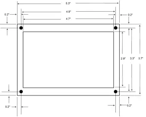
- Mounting: 4.75″ x 5.20” (120.6 mm x 132 mm)
- AC Line voltage: 85 to 240 VAC
- AC line frequency: 50 or 60 Hz
- Sensor accuracy: 2°F at 77°F (1.1°C at 25°C)
- AC combined current limit: 30 Amps
- Compressor output: 2HP
- Sea pump output (SWP): ½ HP
- Loop pump output (CWP): ½ HP
- Valve output (VLV): ½ Amp
- Ambient operating temperature range: 0°F to 180°F (-17.8°C to 82.2°C)
- Maximum Rh conditions: 99% non-condensing
MCC Staging Controller
- Alarm relay contacts: 250 VAC 2A max
- Water sensors: 0.5-4.0 or 1.0-4.5 VDC 0-500 PSI (0-34.5 bar)
Interconnect cables: SUB-059-XXX - Board Dimensions: 4.30″ x 3.90” x 2.0″(109mm x 99mm x 51 mm)
Interconnect Cable Specification:
Flat (oval) multi-conductor shielded modular type cable consisting of stranded tinned copper conductors with thermoplastic insulation and a 22 AWG stranded fused tinned copper drain wire with an overall 100% coverage aluminum/polyester shield in a PVC jacket. Five conductors with drain wire (6 total) are used for the interconnect cables with 26 AWG 7/36 strand wire covered with .009in (Nominal) insulation. Adirondack wire and cable type AWC195 or similar type cable is acceptable.
MCC Wiring Diagram
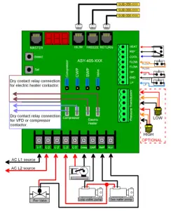
| Micro Air Corp. | |
| MCC wiring | |
| December 03, 2015 I | Rev 1.01 |
| Drawn By: Roger Krinic | |
| ASY-405-XXX | |
MCC Staging Controller Diagram

| Micro Air Corp. | |
| MCC Staging Controller Wiring | |
| December 8. 2015 | I Rev 1.01 |
| Drawn By: Roger Krinic | |
| ASY-406-XXX | |
Note: Three stages shown. One additional display and three additional controls can be connected. Relay contacts are for external alarm relay. Computer connection is for certain legacy systems only.
Two Speed Operation
Special firmware is required for this operation. Two dry contact relays (COMP and EH on the board) are used to control the compressor start and low speed bypass operation. The following 3 charts detail the operation with the available differential and hysteresis settings. Most users will operate using a differential of 2 and a hysteresis of 2.
| Differential = 1 | Differential = 2 | Differential = 3 | ||||||||||||
| Termperature | Increasing Temp | Decreasing Temp | Increasing Temp | Decreasing Temp | Increasing Temp | Decreasing Temp | ||||||||
|
General |
CSP = 48 | COMP Reed Relay (DDC K5, VFD LI1) | EH Reed Relay (DDC K6, VFD LI3) | COMP Reed Relay (DDC K5, VFD LI1) | EH Reed Relay (DDC K6, VFD LI3) | COMP Reed Relay (DDC K5, VFD LI1) | EH Reed Relay (DDC K6, VFD LI3) | COMP Reed Relay (DDC K5, VFD LI1) | EH Reed Relay (DDC K6, VFD LI3) | COMP Reed Relay (DDC K5, VFD LI1) | EH Reed Relay (DDC K6, VFD LI3) | COMP Reed Relay (DDC K5, VFD LI1) | EH Reed Relay (DDC K6, VFD LI3) | |
| Hysteresis = 1 | CSP | 48 | OFF | OFF | OFF | OFF | OFF | OFF | OFF | OFF | OFF | |||
| CSP + 1 | 49 | S1 ON | S1 ON | OFF | OFF | OFF | OFF | OFF | OFF | OFF | ||||
| CSP + 2 | 50 | S2 ON | S2 ON | S1 ON | S1 LS | S1 ON | S1 LS | OFF | OFF | OFF | ||||
| CSP + 3 | 51 | S3 ON | S3 ON | S1 ON | S1 ON | S1 ON | S1 LS | S1 ON | S1 LS | |||||
| CSP + 4 | 52 | S4 ON | S4 ON | S2 ON | S2 LS | S2 ON | S2 LS | S1 ON | S1 LS | S1 ON | S1 LS | |||
| CSP + 5 | 53 | S5 ON | S5 ON | S2 ON | S2 ON | S1 ON | S1 ON | |||||||
| CSP + 6 | 54 | S6 ON | S6 ON | S3 ON | S3 LS | S3 ON | S3 LS | S2 ON | S2 LS | S2 ON | S2 LS | |||
| CSP + 7 | 55 | S6 ON | S6 ON | S3 ON | S3 ON | S2 ON | S2 LS | S2 ON | S2 LS | |||||
| CSP + 8 | 56 | S6 ON | S6 ON | S4 ON | S4 LS | S4 ON | S4 LS | S2 ON | S2 ON | |||||
| CSP + 9 | 57 | S6 ON | S6 ON | S4 ON | S4 ON | S3 ON | S3 LS | S3 ON | S3 LS | |||||
| CSP + 10 | 58 | S6 ON | S6 ON | S5 ON | S5 LS | S5 ON | S5 LS | S3 ON | S3 LS | S3 ON | S3 LS | |||
| CSP + 11 | 59 | S6 ON | S6 ON | S5 ON | S5 ON | S3 ON | S3 ON | |||||||
| CSP + 12 | 60 | S6 ON | S6 ON | S6 ON | S6 LS | S6 ON | S6 LS | S4 ON | S4 LS | S4 ON | S4 LS | |||
| CSP + 13 | 61 | S6 ON | S6 ON | S6 ON | S6 ON | S4 ON | S4 LS | S4 ON | S4 LS | |||||
| CSP + 14 | 62 | S6 ON | S6 ON | S6 ON | S6 ON | S4 ON | S4 ON | |||||||
| CSP + 15 | 63 | S6 ON | S6 ON | S6 ON | S6 ON | S5 ON | S5 LS | S5 ON | S5 LS | |||||
| CSP + 16 | 64 | S6 ON | S6 ON | S6 ON | S6 ON | S5 ON | S5 LS | S5 ON | S5 LS | |||||
| CSP + 17 | 65 | S6 ON | S6 ON | S6 ON | S6 ON | S5 ON | S5 ON | |||||||
| CSP + 18 | 66 | S6 ON | S6 ON | S6 ON | S6 ON | S6 ON | S6 LS | S6 ON | S6 LS | |||||
| CSP + 19 | 67 | S6 ON | S6 ON | S6 ON | S6 ON | S6 ON | S6 LS | S6 ON | S6 LS | |||||
| CSP + 20 | 68 | S6 ON | S6 ON | S6 ON | S6 ON | S6 ON | S6 ON | |||||||
| Hysteresis = 2 | CSP | 48 | OFF | OFF | OFF | OFF | OFF | OFF | OFF | OFF | ||||
| CSP + 1 | 49 | OFF | OFF | S1 ON | S1 LS | OFF | OFF | OFF | OFF | |||||
| CSP + 2 | 50 | S1 ON | S1 LS | S1 ON | OFF | OFF | S1 ON | S1 LS | ||||||
| CSP + 3 | 51 | S1 ON | S2 ON | S2 LS | S1 ON | S1 LS | S1 ON | S1 LS | ||||||
| CSP + 4 | 52 | S2 ON | S2 LS | S2 ON | S1 ON | S1 LS | S1 ON | |||||||
| CSP + 5 | 53 | S2 ON | S3 ON | S3 LS | S1 ON | S2 ON | S2 LS | |||||||
| CSP + 6 | 54 | S3 ON | S3 LS | S3 ON | S2 ON | S2 LS | S2 ON | S2 LS | ||||||
| CSP + 7 | 55 | S3 ON | S4 ON | S4 LS | S2 ON | S2 LS | S2 ON | |||||||
| CSP + 8 | 56 | S4 ON | S4 LS | S4 ON | S2 ON | S3 ON | S3 LS | |||||||
| CSP + 9 | 57 | S4 ON | S5 ON | S5 LS | S3 ON | S3 LS | S3 ON | S3 LS | ||||||
| CSP + 10 | 58 | S5 ON | S5 LS | S5 ON | S3 ON | S3 LS | S3 ON | |||||||
| CSP + 11 | 59 | S5 ON | S6 ON | S6 LS | S3 ON | S4 ON | S4 LS | |||||||
| CSP + 12 | 60 | S6 ON | S6 LS | S6 ON | S4 ON | S4 LS | S4 ON | S4 LS | ||||||
| CSP + 13 | 61 | S6 ON | S6 ON | S4 ON | S4 LS | S4 ON | ||||||||
| CSP + 14 | 62 | S6 ON | S6 ON | S4 ON | S5 ON | S5 LS | ||||||||
| CSP + 15 | 63 | S6 ON | S6 ON | S5 ON | S5 LS | S5 ON | S5 LS | |||||||
| CSP + 16 | 64 | S6 ON | S6 ON | S5 ON | S5 LS | S5 ON | ||||||||
| CSP + 17 | 65 | S6 ON | S6 ON | S5 ON | S6 ON | S6 LS | ||||||||
| CSP + 18 | 66 | S6 ON | S6 ON | S6 ON | S6 LS | S6 ON | S6 LS | |||||||
| CSP + 19 | 67 | S6 ON | S6 ON | S6 ON | S6 LS | S6 ON | ||||||||
| CSP + 20 | 68 | S6 ON | S6 ON | S6 ON | S6 ON |
| Hysteresis = 3 | CSP | 48 | OFF | OFF | OFF | OFF | ||||||||
| CSP + 1 | 49 | OFF | OFF | S1 ON | S1 LS | |||||||||
| CSP + 2 | 50 | OFF | OFF | S1 ON | S1 LS | |||||||||
| CSP + 3 | 51 | S1 ON | S1 LS | S1 ON | ||||||||||
| CSP + 4 | 52 | S1 ON | S1 LS | S2 ON | S2 LS | |||||||||
| CSP + 5 | 53 | S1 ON | S2 ON | S2 LS | ||||||||||
| CSP + 6 | 54 | S2 ON | S2 LS | S2 ON | ||||||||||
| CSP + 7 | 55 | S2 ON | S2 LS | S3 ON | S3 LS | |||||||||
| CSP + 8 | 56 | S2 ON | S3 ON | S3 LS | ||||||||||
| CSP + 9 | 57 | S3 ON | S3 LS | S3 ON | ||||||||||
| CSP + 10 | 58 | S3 ON | S3 LS | S4 ON | S4 LS | |||||||||
| CSP + 11 | 59 | S3 ON | S4 ON | S4 LS | ||||||||||
| CSP + 12 | 60 | S4 ON | S4 LS | S4 ON | ||||||||||
| CSP + 13 | 61 | S4 ON | S4 LS | S5 ON | S5 LS | |||||||||
| CSP + 14 | 62 | S4 ON | S5 ON | S5 LS | ||||||||||
| CSP + 15 | 63 | S5 ON | S5 LS | S5 ON | ||||||||||
| CSP + 16 | 64 | S5 ON | S5 LS | S6 ON | S6 LS | |||||||||
| CSP + 17 | 65 | S5 ON | S6 ON | S6 LS | ||||||||||
| CSP + 18 | 66 | S6 ON | S6 LS | S6 ON | ||||||||||
| CSP + 19 | 67 | S6 ON | S6 LS | S6 ON | ||||||||||
| CSP + 20 | 68 | S6 ON | S6 ON |
MCC Master Display Dimensions
COPYRIGHT
© 2020 Micro Air Corporation, All Rights Reserved
No part of this publication may be reproduced, translated, stored in a retrieval system, or transmitted in any form or by any means electronic, mechanical, photocopying, recording or otherwise without prior written consent by Micro Air Corporation.
Every precaution has been taken in the preparation of this manual to insure its accuracy. However, Micro Air Corporation assumes no responsibility for errors and omissions. Neither is any liability assumed nor implied for damages resulting from the use or misuse of this product and information contained herein.


