ArduCam USB3 Camera Shield User Guide

1 Introduction
This user guide describes the detail operation of ArduCAM USB3 camera shield. The latest device driver, SDK library and examples can be downloaded from the https://github.com/ArduCAM/ArduCAM_USB_Camera_Shield.
2 Hardware Installation
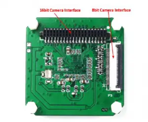
There are two camera interface provided on the USB3 camera shield, but only one camera interface can be used at a time.
2.1 8-bit Camera Interface
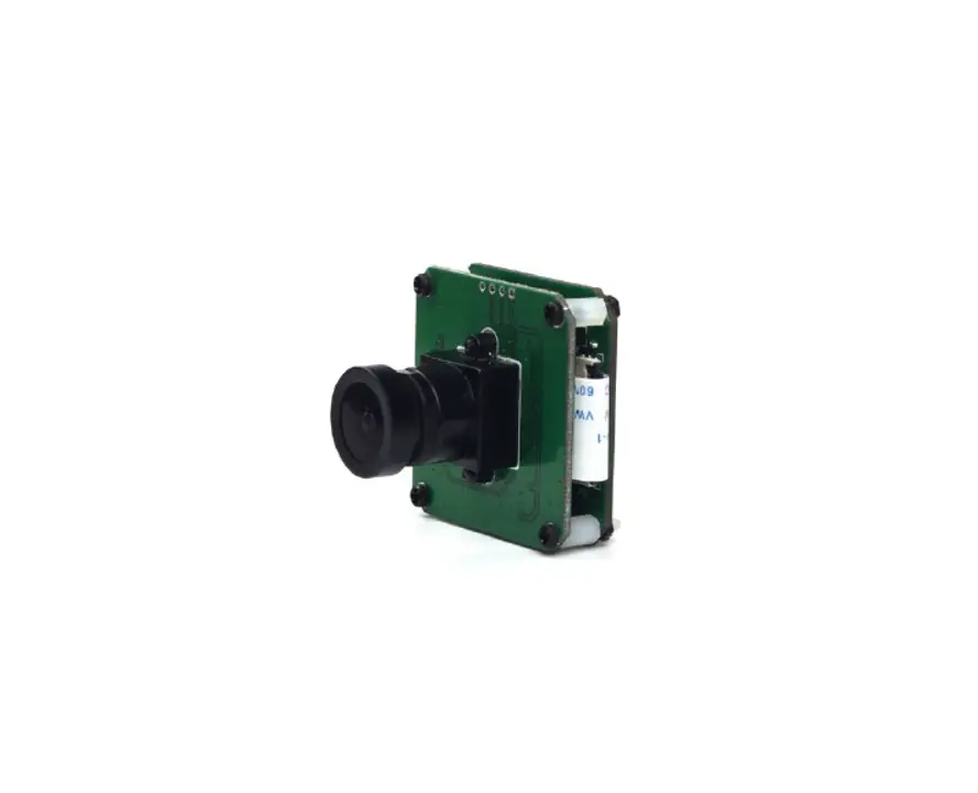
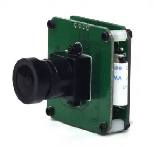
The primary camera interface is used for camera breakout board with 30pin ribbon cable. The pin definition is shown in Table 1. Although the camera breakout board might has more than 8bit data bus, only the upper 8bit connected to the USB camera shield through this FPC connector.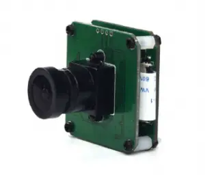
Table 1 8-bit Camera Interface Pin Definition
(Connector Part Number: Hirose FH28D-30S-0.5SH(05))
Pin No. | PIN NAME | TYPE | DESCRIPTION |
| 1 | GND | Ground | Power ground |
| 2 | Reserved | NC | |
| 3 | Reserved | NC | |
| 4 | VSYNC | Input | Active High: Frame Valid; indicates active frame |
| 5 | HREF | Input | Active High: Line/Data Valid; indicates active pixels |
| 6 | DOUT11 | Input | Camera Pixel Data Input 11 (MSB) |
| 7 | DOUT10 | Input | Camera Pixel Data Input 10 |
| 8 | DOUT9 | Input | Camera Pixel Data Input 9 |
| 9 | DOUT8 | Input | Camera Pixel Data Input 8 |
| 10 | DOUT7 | Input | Camera Pixel Data Input 7 |
| 11 | DOUT6 | Input | Camera Pixel Data Input 6 |
| 12 | DOUT5 | Input | Camera Pixel Data Input 5 |
| 13 | GND | Ground | Power ground |
| 14 | DOUT4 | Input | Camera Pixel Data Input 4 (LSB) |
| 15 | DOUT3 | Input | Camera Pixel Data Input 3 (Unconnected) |
| 16 | DOUT2 | Input | Camera Pixel Data Input 2 (Unconnected) |
| 17 | DOUT1 | Input | Camera Pixel Data Input 1 (Unconnected) |
| 18 | DOUT0 | Input | Camera Pixel Data Input 0 (Unconnected) |
| 19 | Reserved | NC | |
| 20 | PCLK | Input | Pixel Clock output from Camera |
| 21 | SCL | Output | Two-Wire Serial Interface Clock |
| 22 | SDATA | Bi-directional | Two-Wire Serial Interface Data I/O |
| 23 | RST | Output | Sensor reset signal, active low |
| 24 | GND | Ground | Power ground |
| 25 | GND | Ground | Power ground |
| 26 | STANDBY | Output | Standby-mode enable pin (active HIGH) |
| 27~30 | VCC | POWER | 3.3v Power supply |
2.2 16-bit Camera Interface
The secondary camera interface is used for MIPI camera, stereo-camera or customized camera adapter boards which support up to 16bit data bus. The pin definition is shown in Table 2.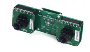
Table 2 16-bit Camera Interface Pin Definition (Connector Part Number: Harwin M50-4302045)
Pin No. | PIN NAME | TYPE | Pin No. | PIN NAME | TYPE |
| 1 | VCC3.3 | POWER | 2 | VCC3.3 | POWER |
| 3 | GND | Ground | 4 | GND | Ground |
| 5 | SDATA | Bi-directional | 6 | SCL | Input |
| 7 | Data10 | Input | 8 | Data12 | Input |
| 9 | Data11 | Input | 10 | Data13 | Input |
| 11 | Data8 | Input | 12 | Data6 | Input |
| 13 | Data3 | Input | 14 | Data0 | Input |
| 15 | RST | Output | 16 | Data4 | Input |
| 17 | Data7 | Input | 18 | Data9 | Input |
| 19 | Reserved | NC | 20 | STANDBY | Output |
| 21 | Reserved | NC | 22 | Reserved | NC |
| 23 | Data14 | Input | 24 | HREF | Input |
| 25 | Reserved | NC | 26 | VSYNC | Input |
| 27 | Reserved | NC | 28 | GND | Ground |
| 29 | PCLK | Input | 30 | GND | Ground |
| 31 | Data1 | Input | 32 | Data5 | Input |
| 33 | Reserved | NC | 34 | Data15 | Input |
| 35 | Data2 | Input | 36 | Reserved | NC |
| 37 | Reserved | NC | 38 | Reserved | NC |
| 39 | Reserved | NC | 40 | USB_RST | Input |
3 Device Driver Installation
Please download the device driver from github. The Windows device driver is located in Drivers folder like WinXP,Win7 or Win10. In each driver folder there are x64 and x86 folders for 64bit and 32bit system respectively. When install the driver on Windows, you might need to disable the Windows driver signature by following the two video below:
https://youtu.be/gOTkrFp8oM4
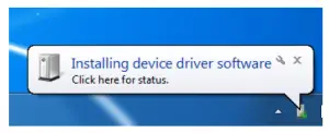
Plug in the USB cable to the camera and the host PC USB port, there is notification from the lower right of the task bar. The auto installation of the driver will fail, so we have to install the USB camera driver manually.
Go to Start->Settings->Control-Panel->Device Manager, right click the unknown device and select “Update Driver Software”.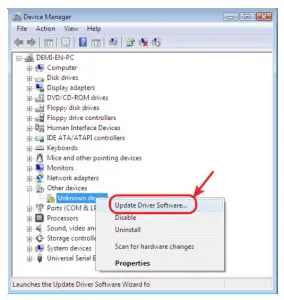
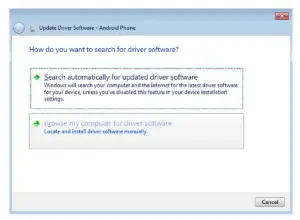
Select the “Browse my compute for driver software”
Select “Let me pick from a list of device drivers on my computer”.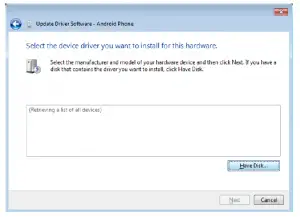
ArduCAM USB3 Camera Shield User Guide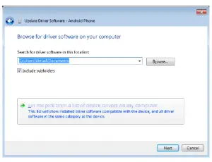
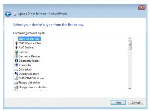
Select “Show All Devices”.
ArduCAM USB3 Camera Shield User Guide
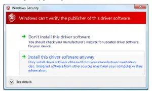
Confirm the installation of the driver by pressing “Yes”.
Confirm the installation again by pressing “Install”.

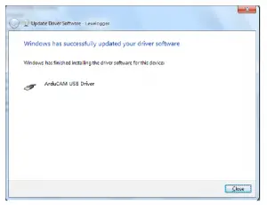
You will successfully install the driver like this.

4 Demo Code
The demo code is provided in source code form to help user to understand the operation the ArduCAM USB camera and SDK library. It is created with Microsoft Visual Studio 2013 and
based on MFC frame work.
The Windows demo code is located in ../Winodws/USBTest folder and the release executable software is located in ../Winodws/USBTest/USBTest.exe.
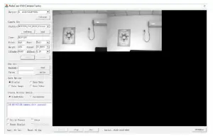
4.1 Scan Cameras
Click the scan button, the drop down list will show all supported cameras with serial number,
4.2 Load the Camera Settings
There are several preset of the camera settings in the Config folder, select one of the corresponding camera setting from the drop list and click load to load the setting. The camera type, width, height, bits, format, I2CAddr, I2CMode will be loaded with the correct values.
4.3 Open the Camera
Click Open to open the camera selected from the camera drop list.
4.4 Play the Video
Click the Play to capture and display the video in real-time.
4.5 Stop the Video
Click the Stop button to stop the video capture and display
4.6 Take a Snapshot
Click the Shot to take BMP image to files.
4.7 Sensor Register Read/Write
This is very useful to access the sensor register in order to adjust the sensor settings on the fly. For example you want to manually change the exposure settings you can input the exposure register address and value then click write, you can video how the brightness changes from the video.
4.8 RAW Mode Selection
There are four combination of the RAW format R-G, G-R, B-G, G-B. It is predefined for tested camera, you can also changes the mode match your target sensor RAW display order
4.9 Camera Control
4.9.1 Fit to Window
To fit the captured image to the GUI windows size. If this is unchecked, user can use mouse scroll wheel to zoom in and out the real-time video, or drag the mouse cursor to move the video position.
4.9.2 Force Display
Force display is useful to debug the problem by force displaying the wrong video data which is mismatch with the camera preset values.
4.9.3 IRcut
It can be used to manual control extra motorized IRCUT filter for both daylight and night vision.
4.9.4 Frame Rate Information
The frame rate information show the capture frame rate and GUI display frame rate. These two values might be mismatched, due to the performance of the demo GUI software and computer hardware.
4.10 Image Save Options
There are several options for saving image files and format. The Display option doesn’t save any file just real-time display the video from the camera. The Save Data option is used to save the continuous images in the same format as the camera output like RAW, RGB, YUV or JPEG. The Save Image option is used to save the BMP images. The Save Video options is used to save the AVI format video. Except the Display option, when checking other options, the video is not updated on the display region.
4.11 Stereo Display Options
This options are only available when using stereo camera adapter board. The SideBySide option displays the video in left and right order. The UpsideDown option displays the video up and down order.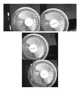
Read More About This Manual & Download PDF:


