![]() PT-871xr Quick Start Guide
PT-871xr Quick Start Guide
Scan for full manual
kramer-pt-871-2-kit-pt-871-2xr-kit-wp-871xr-wp-872xr-pt-871xr-pt-872xr-um-2 [PDF]
This guide helps you install and use your PT-871xr for the first time.
Go to www.kramerav.com/downloads/PT-871xr to download the latest user manual and check if firmware upgrades are available.
Step 1: Check what’s in the box
![]() PT-871xr HDMI 4K Line Transmitter
PT-871xr HDMI 4K Line Transmitter![]() 1 Power adapter and cord
1 Power adapter and cord![]() 4 Rubber feet
4 Rubber feet![]() 1 Quick start guide
1 Quick start guide![]() 1 Bracket set
1 Bracket set
IMPORTANT NOTICE!
![]() We highly recommend using only Kramer UNIKAT cables with these products. If using 3rd party shielded CAT-6A cables, both ends of the shield must be soldered to the connectors for the products to function properly. Do not use any jumpers, unshielded wall plates or midspan cable connections. These extenders are not compatible with HDBaseT technologies. Prior to signal extension, ensure that the extension line cable is lying straight and not coiled.
We highly recommend using only Kramer UNIKAT cables with these products. If using 3rd party shielded CAT-6A cables, both ends of the shield must be soldered to the connectors for the products to function properly. Do not use any jumpers, unshielded wall plates or midspan cable connections. These extenders are not compatible with HDBaseT technologies. Prior to signal extension, ensure that the extension line cable is lying straight and not coiled.
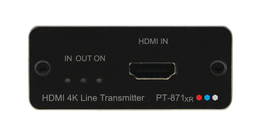
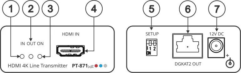
Step 2: Get to know your PT-871xr
 The terms HDMI, HDMI High-Definition Multimedia Interface, and the HDMI Logo are trademarks or registered trademarks of HDMI Licensing Administrator, Inc.
| 1 | Feature | Function | ||
| LED Indicators | IN | Lights when an active source is connected to HDMI IN. | ||
| 2 | OUT | Ligh -8ts when an active acceptor is connected to HDMI OUT on the receiver (for example, WP72xr | ||
| 3 | ON | Lights when power is connected to the device. | ||
| 4 | HDMI™ IN Connector | Connect to an HDMI source. | ||
| 5 | SETUP DIP-switches | Set the operation DIP-switches. Both DIP-switches are set to OFF (up) by default. | ||
| DIP-switch 1: Compression Options | OFF (up) — Standard compression level. ON (down) — High compression level for additional range extension. | |||
| DIP-switch 2: Compression Setup | OFF (up) — Enable compression (mandatory). ON (down) — For future use. | |||
| 6 | DGKat-2.0 OUT RJ-45 Connector | Connect to the DGKat-2 0 IN connector on the receiver (for example, WP-872×0 using twisted pair cable. | ||
| 7 | 12V DC Connector | Connect the power adapter to one of the devices. | ||
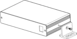
Step 3: Install the PT-871xr
Install PT-871xr using one of the following methods:
- Attach the rubber feet and place the unit on a flat surface.
- Fasten a bracket (included) on each side of the unit and attach it to a flat surface (see www.kramerav.com/downloads/PT-871xr).
- Mount the unit in a rack using the recommended rack adapter (see www.kramerav.com/product/PT-871xr).
- Ensure that the environment (e.g., maximum ambient temperature & air flow) is compatible for the device.


- Ensure that the environment (e.g. maximum ambient temperature & air flow is compatible for te device.
- Avoid uneven mechanical loading.
- Appropriate consideration of equipment nameplate ratings should be used for avoiding overloading of the circuits.
- Reliable earthing of rack-mounted equipment should be maintained.
PT-871xr Quick Start

P/N: 2 9 0 0 – 3 0 1 2 3 4 QS
Step 4: Connect the inputs and outputs
Always switch OFF the power on each device before connecting it to your PT-871xr.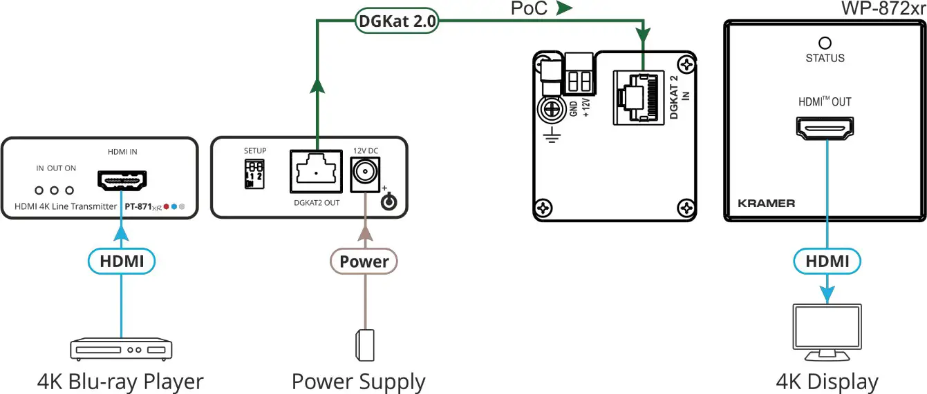
![]() To achieve specified extension distances, use the recommended Kramer cables to connect AV equipment to the PT-871xr (available at www.kramerav.com/product/PT-871xr). Using third-party cables may cause damage!
To achieve specified extension distances, use the recommended Kramer cables to connect AV equipment to the PT-871xr (available at www.kramerav.com/product/PT-871xr). Using third-party cables may cause damage!
Step 5: Connect the power
Connect the 12V power adapter to the PT-871xr and plug it into the mains electricity. This device provides power to its counterpart via DGKat 2.0. Each device can provide or accept power over cable (PoC) via DGKat 2.0.
Safety Instructions (See www.kramerav.com for updated safety information)![]()
Caution:
- For products with relay terminals and GPIO ports, please refer to the permitted rating for an external connection, located next to the terminal or in the User Manual.
- There are no operator serviceable parts inside the unit.
Warning:
- Use only the power cord that is supplied with the unit.
- Disconnect the power and unplug the unit from the wall before installing.
Step 6: Technical Specifications
| Inputs | 1 HDMI | On a female HDMI connector |
| Outputs | 1 DGKAT 2.0 | On a female RJ-45 connector |
| Video | Transmitted Data Bandwidth | Up to 18Gbps (6Gbps per graphic channel) |
| Max Resolution | 3840×2160@60Hz (4:4:4) 24bpp at high compression level 4096×2160@60Hz (4:4:4) 24bpp at standard compression level | |
| Compliance | HDMI 2.0, HDCP 2.2, HDR 10 | |
| Reach Extension | Standard Compression Level | Up to 40m (130ft) at 4K@60Hz (4:4:4) Up to 70m (230ft) at 4K@60Hz (4:2:0) or full HD (1080p @60Hz 36bpp) |
| High Compression Level | Up to 60m (200ft) at 4K@60Hz (4:4:4) Up to 70m (230ft) at 4K@60Hz (4:2:0) or full HD (1080p @60Hz 36bpp) | |
| Controls | Front Panel | IN, OUT and ON LEDs |
| Rear Panel | DIP-switches | |
| Power | Consumption | 12V DC, 600mA |
| Source | 12V DC, 2A | |
| Environmental Conditions | Operating Temperature | 0° to +40°C (32° to 104°F) |
| Storage Temperature | -40° to +70°C (-40° to 158°F) | |
| Humidity | 10% to 90%, RHL non-condensing | |
| Regulatory Compliance | Safety | CE, UL |
| Environmental | RoHs, WEEE | |
| Enclosure | Size | Pico Tool |
| Type | Aluminum | |
| Cooling | Convection Ventilation | |
| Accessories | Included | 1 Power adapter, 1 power cord |
| Specifications are subject to change without notice at www.krameray.com | ||


