![]() F106D – 4K Jasper Lake Fanless Digital Signage Media Player
F106D – 4K Jasper Lake Fanless Digital Signage Media Player
User Manual
F106D – 4K Jasper Lake Fanless Digital Signage Media Player
Statement
The copyright of this manual belongs to Shenzhen JEHE Technology Development Co., Ltd.
(Giada, JEHE’s global brand) and all rights are reserved. The company reserves the right to change this manual at any time without notification. Specifications here are for reference only, please take the real product as standard.
Without official authorization of Giada, other companies or individuals may not copy, plagiarize, translate, or disseminate this manual for commercial purpose.
The information provided in this manual is accurate and reliable. The company does not take any legal responsibility for the consequences of infringement use of this manual.
Safety Notice
- Read the user manual carefully before setting up the Giada product.
- Disconnect the power cord before installing the internal components
- Most electronic components are sensitive to static electrical charge, please wear a wrist-grounding strap when installing the internal components.
- Do not disconnect the power cord when the system is running to avoid damage to the sensitive components by instantaneous surge voltage.
Contact Information
Shenzhen JEHE Technology Development Co., Ltd.
Website: www.giadatech.com
Phone: +86-755-3330 0336
Email: [email protected]
Address: 1~3/F, Block A, Tsinghua Information Harbor, North Section, Shenzhen Hi-tech
Park, Nanshan District, Shenzhen, China
Product Introduction
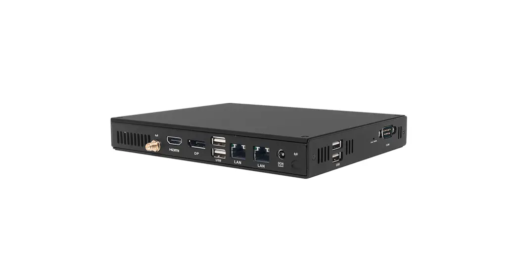
Based on Jasper Lake platform, Giada F106D has both fan and fanless design options. Giada F106D adopts LPDDR4 dual-channel memory as well as M.2 and mSATA storage interface design. With one DP and one HDMI displays output, it can support 4K 60Hz display. The player is suitable to be applied in mainstream digital signage applications.
Interface Description and Hardware Specifications
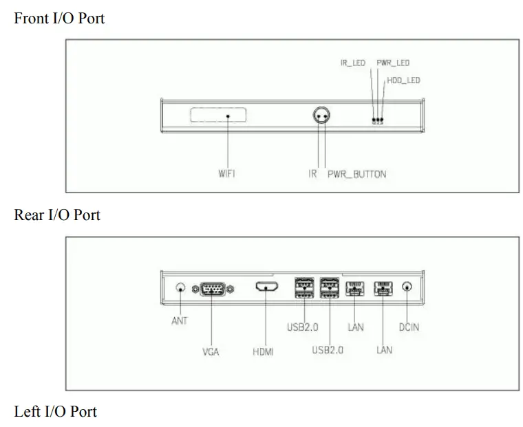
2.1 Interface Description

2.2 Hardware Specifications
| F106D | |||
| Processor | CPU | Inter Jasper Lake Celeron N5095(Fan)/N5100 (Fanless) | |
| BIOS | AMI EFI 64 Mbit | ||
| Chipset | SoC | ||
| Memory | Type | LPDDR4-2666MHz | |
| Socket | Onboard | ||
| Channel | 2 | ||
| Size | 4GB (Optional: 8GB) | ||
| Graphics | GPU | Intel` UHD Graphics | |
| Graphic Engine | DirectX 12.1, OpenGL 3.0. OpenCL 1.1, OpenGL ES 2.0. H.264, MEPG2 | ||
| Interface | 1 x OP (Max.3840 x 2160 Q60Hz) | ||
| 1 x HDMI (Max.4096 x 2160 /160Hz) | |||
| Network | Controller | RTL 8111I-1 Gigabit Ethernet |
| Interface | 1 x RJ45 (Optional: 2 x RJ45) | |
| 110 Interface | USB | 2 x USB3.2 Gen2. 4 x USB2.0 |
| Serial Port | 1 x RS232 | |
| Audio | 1 x MIC-IN. 1 x AUDIO-OUT | |
| Wireless | 1 x E-key M.2 (2230) for WiFi/BT | |
| SIM Card | 1 x SIM-Slot | |
| JAHC | WatchDog Timer | 0-255 Second Time Out Support |
| Auto Power On | Power Activated Automatically Start | |
| RTC | Set Up Independently Every Day | |
| Remote Control | Wake on LAN | |
| Storage | Socket 1 | 1 x M-key M.2 (224212280) for SSD |
| Socket 2 | 1 x Full-size Mini-PCIe for MSATA 3G/4G | |
| Onboard | eMMC 5.1 (optional) | |
| Operation System | Windows | Windows 10 (64-bit ) |
| Linux | Ubuntu 18.04 | |
| Power | Power Type | DC-IN |
| Power Adapter | 12V/19V | |
| Mechanical | Construction | Metal |
| Mounting | VESA Mounting JZ183 | |
| Dimension (Wx D x H) | 189.6mm x 148.3mm x 26mm (7.46″ x 5.83″ x 1.07) | |
| Color | Black | |
| Environment | Operating Temperature | 0-40-0 ( 32°F- 104°F) at 0.7m/s Air Flow |
| Relative Humidity | 95%©40C (non-condensing) | |
| Certification | CE. FCC |
Accessories Installation Steps
![]() For safety reasons, please ensure that the power cord is disconnected before opening the case.
For safety reasons, please ensure that the power cord is disconnected before opening the case.
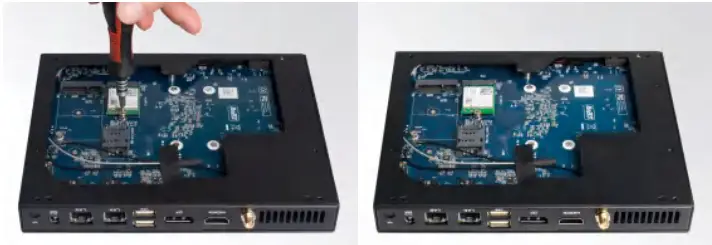
How to open the cover
Unscrew the four screws and push to open the case. (1 x M.2 for SSD are on top side).
Unscrew the four screws, push the bottom cover and remove it. (1 x Mini-PCIe for 3G/4G or mSATA, 1 x M.2 (2230) for WiFi/BT, SIM card slot are on bottom side).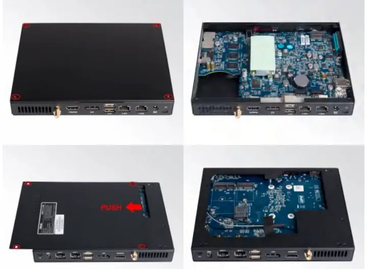
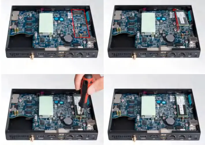
3.2 WIFI (M.2) Installation
- Plug the WIFI module into the appropriate slot.
- Secure the module to the carrier by tightening up the screw.
- Connect the two black cables to Main and AUX. Install antennas.


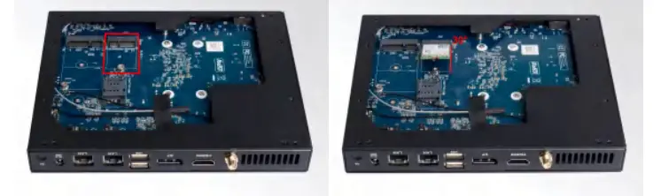
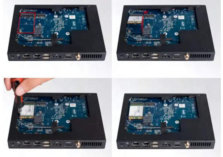
3.3 3G/4G/ Installation
Default SMA connector and cable is for WIFI. Please change to 3G/4G/5G SMA connector and cable.
- Plug the 3G/4G module into the Mini-PCIe slot.
- Secure the module to the carrier by tightening up the screw.
- Connect the cable to Main and install the antenna.

3.6 SIM Card Installation![]() This product supports standard SIM card with the size of 25mm × 15mm.
This product supports standard SIM card with the size of 25mm × 15mm.
- [Open] the SIM card holder and pull it up.
- Insert the SIM card.
- [Lock] the card holder.

Bios Setup
Notice:
The descriptions relating to BIOS setup in this Manual is for reference only since the BIOS version of the product might be upgraded. Giada provides no guarantee that all the contents in this Manual are consistent with the information you acquired.
BIOS is a basic I/O control program saved in the Flash Memory. Bridging the motherboard and the operation system, BIOS is used for managing the setup of the related parameters between them.
When the computer is activated, the system is first controlled by the BIOS program. Firstly, a self-detection called POST is performed to check all hard devices and confirm the parameters of the synchronous hardware.
Once all detections are completed, BIOS will hand over the controlling to the operation system (OS).
As BIOS serves as the only channel that connects the hardware and software, whether your computer can run stably and work in optimized state will hinge on how to properly set the parameters in BIOS.
Therefore, the correct setup of BIOS plays a key role in stably running the system and optimizing its performance.
The CMOS Setup will save the set parameters in the built-in CMOS SRAM on the motherboard.
When the power is shut off, the lithium battery on the motherboard will provide continuously power to CMOS SRAM.
The BIOS setup program will allow you to configure the following items:
- HD drive and peripheral devices
- Video display type and display items
- Password protection
- Power management characteristics
A. State of BIOS Setup
When the computer is started up, BIOS will run the self-detection (Post) program. This program includes series of diagnosis fixed in BIOS. When this program is executed, the following information will appear if any error is found:
Press [F1] to Run General help
Press [F2] to Load previous values and continue
To enter BIOS, you can press F2; to load the default values and enter the system, you can press DEL to enter the BIOS interface if no error is found. If the indicative information disappears before you operate, you can shut off the computer and turn it on again, or you can press the RESET key on the product case. To restart your computer, you can also simultaneously press < Ctrl > + < Alt > + < Delete >.
B. Function Keys definitions
| Hot Key | Description |
| ↑ | (Up key) Move to the previous item |
| ↓ | (Down key) Move to the next item |
| ← | (Left key) Move to the left item |
| → | (Right key) Move to the right item |
| ESC | Exit the current interface |
| Page Up | Change the setup state, or add the values |
| Page Down | Change the setup state, or deduct the values |
| F1 | Display the information of the current function Keys definitions. |
| F9 | Load the optimized values |
| F10 | Save the settings and exit the CMOS SETUP |
C. Auxiliary information Main interface
When the system enters the main interface of Setup, the major selected contents will be displayed at the lower part of the interface with the change of the options.
When you set the value for each column, you can view the preset value of the column and the values that can be set if you press F2, for example, the BIOS default values or CMOS Setup values.
To exit the interface for auxiliary information, press [ESC].
- Main menu
When the system enters the CMOS Setup menu, you can see the main menu on the upper part of the screen, as shown in Figure1.
In this main menu, you can use the left and right direction keys to select the setup items.
Once the item is selected, the lower part of the computer screen will show the details of setting.
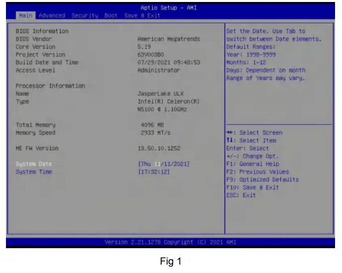
- Main (standard CMOS setup)
This item is used for setting the date and time. - Advanced (advanced BIOS setup)
This item is used for setting the advanced functions provided by BIOS, such as specifications of PCIe facilities,CPU, HDD, etc. - Chipset
- Security (set the administrator/user password)
- Boot (startup configuration characteristics)
- Save & Exit (option of exit)
This item includes load optimal defaults/load failsafe defaults value/discard changes/discard changes and exit.
4.1 Main (Standard CMOS setting)

- System time (hh:mm:ss)
Use this item to set the time for the computer, with the format as “HH / MM / SS”. - System date (mm:dd:yy)
Use this item to set the date for the computer, with the format as “week, MM / DD / YY”.
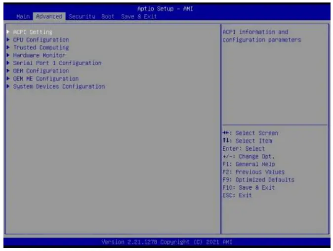
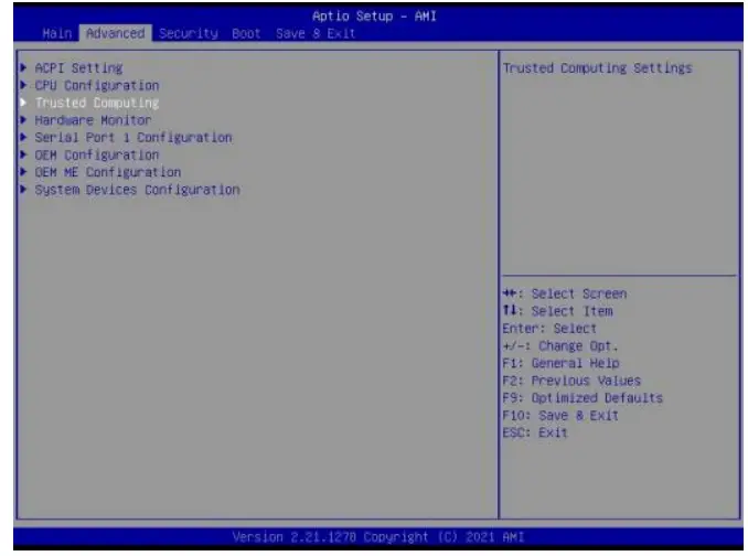
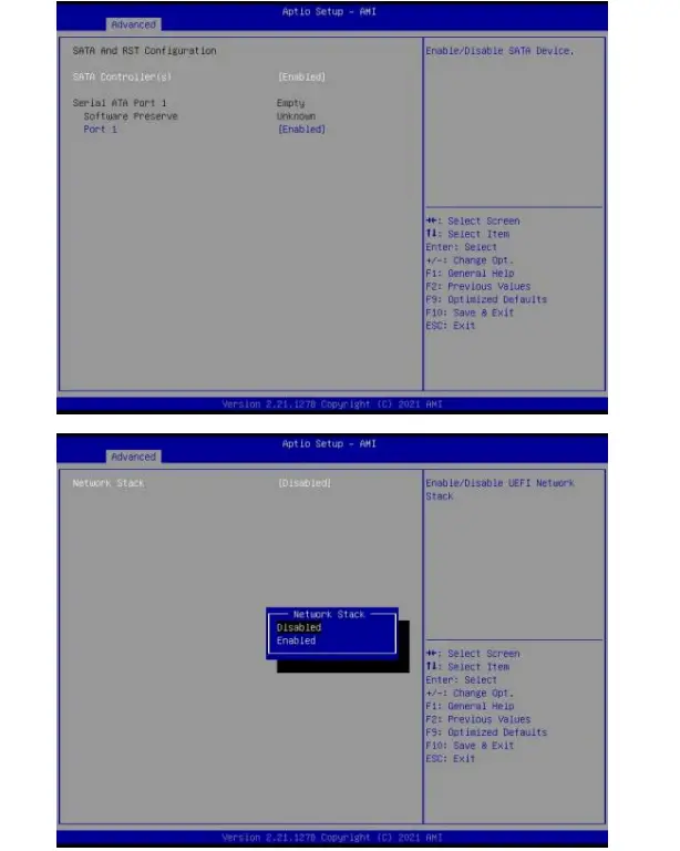
4.2 Advanced (Advanced BIOS setup)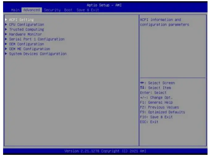
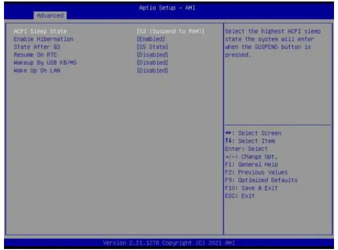
4.2.1 ACPI Setting
| ACPI Menu | Description |
| ACPI Sleep State | • Select the highest ACPI sleep state the system will enter when the SUSPEND button is pressed. |
| Enable Hibernation | • Enables or disables system ability to Hibernate (OS/S4 Sleep). This option may be not effective with some OS. |
| State After G3 | • State After G3 means after restore power supply. • S5 State (Default): If set it as S5 State, it means the system will remain shutdown state • S0 State: If set it as S0 State, it means the system will be power on automatically. • Last State: If set it as Last State, it means the system will keep State of last setup. |
| Resume On RTC | • Enable or disable System wake on alarm event. Select FixedTime, system will wake on the hr::min::sec specified. Select DynamicTime,System will wake on the current time + Increase minute(s). |
Wake Configuration
| ACPI Menu | Description |
| Wakeup By USB KB/MS | Enabled or Disabled Wake Up by USB KB/MOUSE from S3 Status. • Disabled: The wake on USB is disabled by default. • Enabled. |
| Wake Up On LAN | Wake On LAN Function. • Disabled: The WOL is disabled by default. • Enabled. |
4.2.2 CPU Configuration
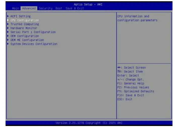
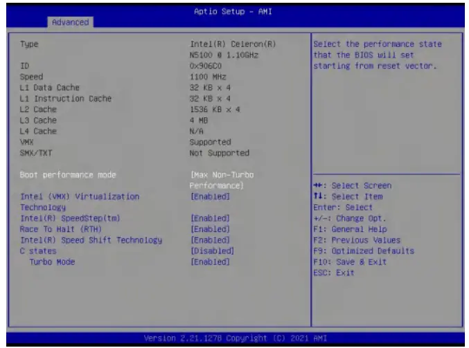
| CPU Configuration Menu | Description |
| Boot performance mode | l Max Non-Turbo Performance: the best performance. l Max Battery. l Turbo performance. |
| Intel (VMX) Virtualization Technology | Intel Virtualization Technology is enabled by default. User can enable and disable the Intel Virtualization Technology function. |
| Intel(R) SpeedStep(tm) | Intel(R) SpeedStep Technology dynamically increases the processor’s frequency as needed by taking advantage of thermal and power headroom to give you a burst of speed when you need it, or increased energy efficiency. The option is enabled by default. You can disable the function if it’s necessary. |
| Race To Halt(RTH) | The Race To Halt(RTH) function is enable by default. It can adjust the CPU base frequency work in C-state. Optional: C-state. |
| CPU Configuration Menu | Description |
| Intel(R)Speed Shift Technology | Intel speed shift function is enabled by default. Intel® Speed Shift Technology uses hardware-controlled P-states to deliver dramatically quicker responsiveness with single-threaded, transient (short duration) workloads, such as web browsing, by allowing the processor to more quickly select its best operating frequency and voltage for optimal performance and power efficiency. |
| C states | The C-State function is disabled by default. |
| Turbo Mode | • Disabled. • Enabled. |
4.2.3 Trusted Computing
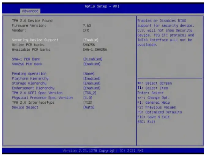
| Trusted Computing | Description |
| TPM20 Device Found | l TPM2.0 device information. |
| Security Device Support | l Enables or Disables BIOS support for security device. OS will not show security device. TCG EFI protocol and INT1A interface will not be available. |
| SHA-1 PCR Bank | l Enabled/Disabled SHA-1 PCR Bank |
| SHA256 PCR Bank | l Enabled/Disabled SHA256 PCR Bank |
| Pending operation | l Schedule an operation for the security device. Note: Your computer will reboot during restart in order to change State of security device. |
| Platform Hierarchy | l The user can enable or disable this item. |
| Storage Hierarchy | l The user can enable or disable this item. |
| Endorsement Hierarchy | l The user can enable or disable this item. |
| TPM2.0 UEFI spec version | Select the TCG2 SPEC version support. l TCG_1_2: The compatible mode for win8/win8. l TCG_2: Support new TCG2 protocol and event format for win10 or later. |
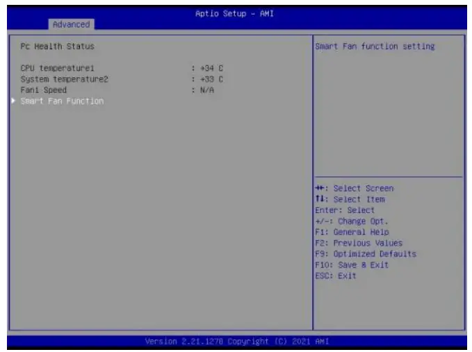
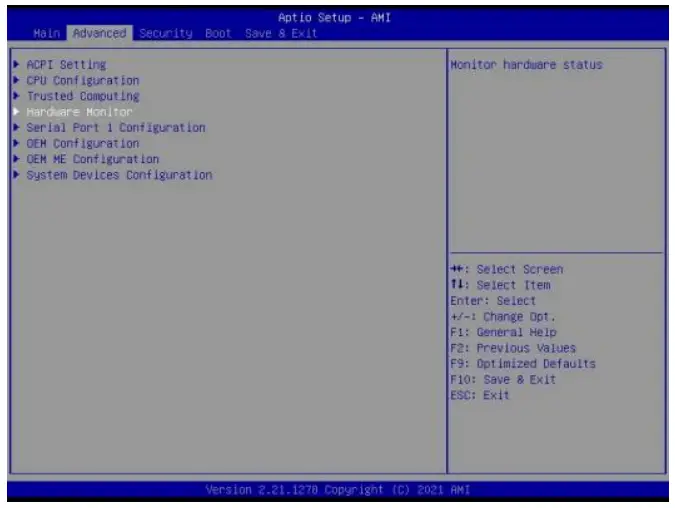
4.2.4 Hardware Monitor
4.2.5 Serial Port 1 Configuration
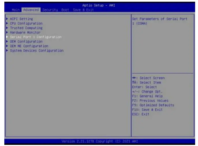
| Serial Port 1 Configuration | Description |
| Serial Port 1 Configuration | This item can be used to set the Serial Port 1 after entering the Serial Port 1 Configuration. It can be set according to user’s needs. |
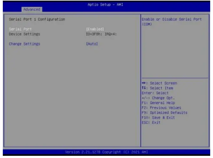
| Serial Port 1 Configuration | |
| Serial Port | The serial port is enabled by default. l Enabled l Disabled. |
| Device Settings | IO-3F8h; IRQ=4; |
| Change settings | User can set the serial port by change settings option. l Auto l IO=3E8H;IRQ=4; l IO=3F8H;IRQ=3,4,5,6,7,9,10,11,12; l IO=2F8H;IRQ=3,4,5,6,7,9,10,11,12; l IO=3E8H;IRQ=3,4,5,6,7,9,10,11,12; l IO=2E8H;IRQ=3,4,5,6,7,9,10,11,12。 |
4.2.6 OEM Configuration
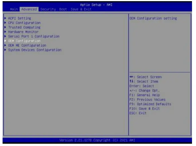
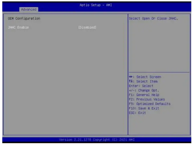
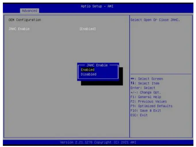
| OEM ME Configuration Menu | Description |
| JAHC Enable | Control Unit (MCU) and software (JAHC Technology Manager). l Disabled: The JAHC is disable by default. l Enabled. |
4.2.7 OEM ME Configuration
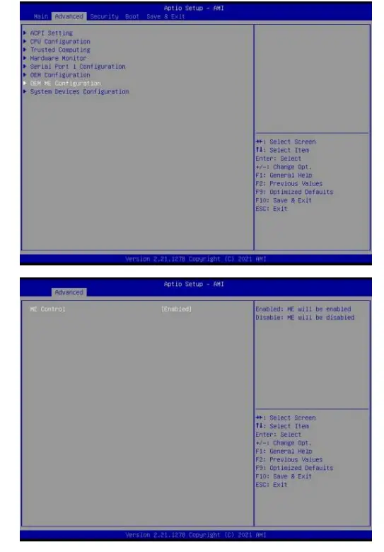
| OEM ME Configuration menu | Description |
| ME Control | l Enable and disable ME control. When disabled ME will be put into ME Temporarily disabled Mode. |
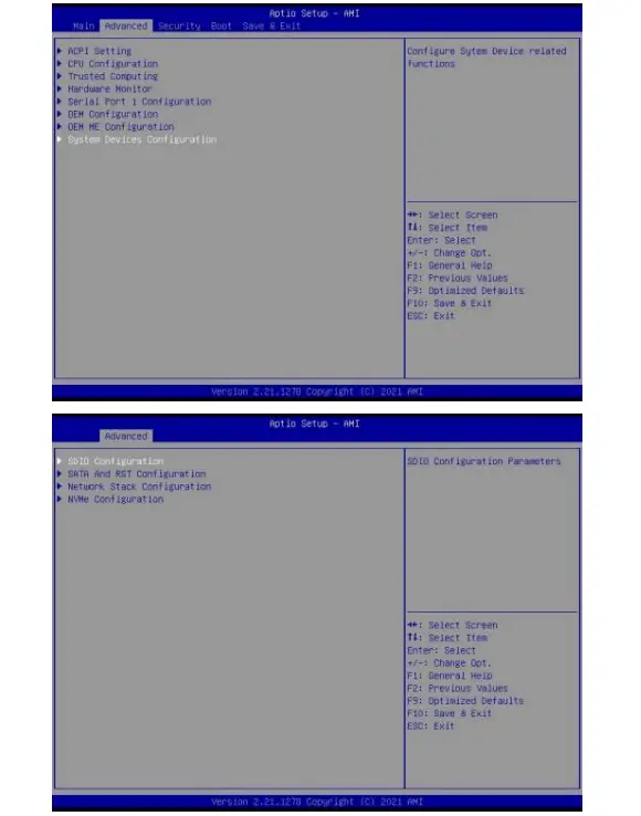
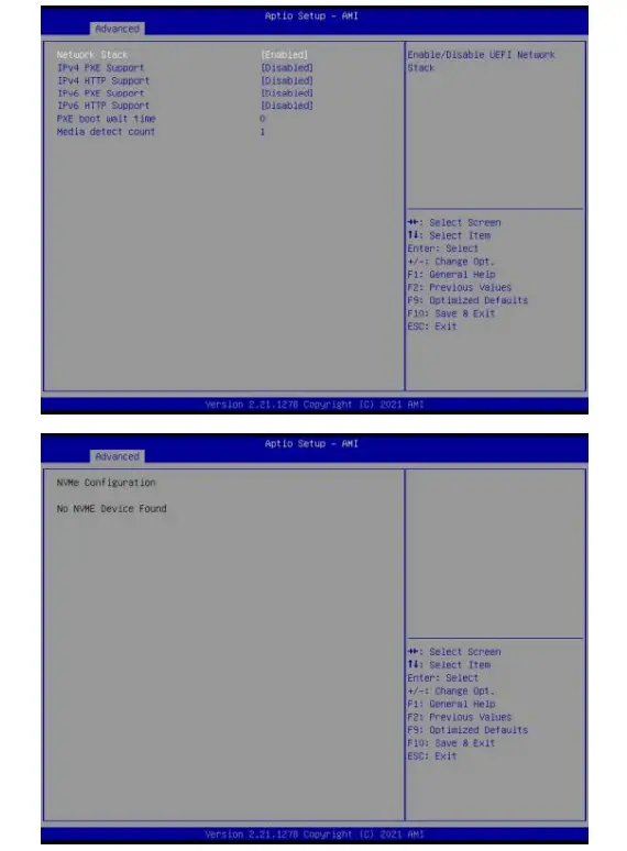
4.2.8 System Devices Configuration
4.3 Security
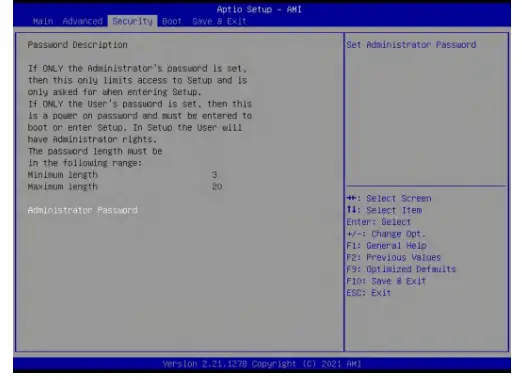
If this function is selected, the following information will appear:
Enter New Password hhhhhh
Then enter a password which is no more than eight characters and press <Enter>. BIOS will require to enter the password again.
Once you enter it again, BIOS will save the set password. Once the password item is enabled, you will be required to enter the password every time before the system entering to the setup program of BIOS. The user can set this item through the Security Option in advanced BIOS properties. If the Security Option is set as System, the password will be required to be entered before both the system guides and entering to the setup program of BIOS. If it is set as Setup, the password will be required to be entered only before the system entering to the setup program of BIOS.
To delete the password, press <Enter> in the popped-up window that requires to enter the password.
Then information for confirmation will appear on the screen to allow you decide whether the password will be disabled. Once the password is disabled, you can enter the setup program directly without password when the system is restarted.
4.4 Boot Menu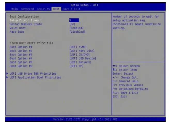
| Boot Menu | Description |
| Boot Configuration | |
| Setup Prompt Timeout | • This item is use to set the wait time of entering the operation system. During the BIOS post, if user doesn’t press the keyboard, it won’t respond unless you reboot the BIOS. The Setup Prompt Timeout is 3s by default. You can set the time as you want. |
| Bootup NumLock State | • Options are OFF and ON. In other words, this item can be used to set the state of Num Lock after entering the system. It can be set according to user’s needs and doesn’t affect the performance of the computer. |
| Quiet Boot | • If this item is set as Enabled, the system can be started within five seconds and some detection items will be ignored. The options are [Disabled] and [Enabled]. |
| Fast Boot | • Enables or disables boot with initialization of a minimal set of devices required to launch active boot option. Has no effect for BBS boot options. |
| Boot Menu | Description |
| Boot Option #1 | l The first boot device. If BIOS doesn’t detect the first boot device, it will check the second boot device. |
| Boot Option #2 | l The second boot device. |
| Boot Option #3 | l The third boot device. |
| Boot Option #4 | l The fourth boot device. |
| Boot Option #5 | l The fifth boot device. |
| Boot Option #6 | l The sixth boot device. |
| UEFI USB Driver BBS Priorities | l Specifies the boot Device Priority sequence from available UEFI USB Drivers. |
| UEFI Application Boot Priorities | l Specifies the boot Device Priority sequence from available UEFI Application. |
4.6 Save & Exit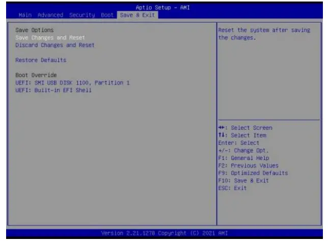
| Save Exit Item | Description |
| Save Options | |
| Save Changes and Reset | l Save all changes and exit |
| Discard Changes and Reset | l Give up the settings and exit. |
| Restore Defaults | l Recover it to default. |
| Boot Override | l Whole Boot devices |
JAHC Introduction
JEHE Active Hardware Control (JAHC) management system includes both hardware Micro Control Unit (MCU) and software (JAHC Technology Manager). It can support following functions:
- Automatically boot up when power on. It is controlled by the Micro Control Unit (MCU) chip.
- Real Timer Controller (RTC) wake up: user can install the JAHC software to set up automatic startup and shutdown, one week as a circle.
- Watchdog timer. It is a built-in API interface.
- Infrared remote control (Optional IR controller).
5.1 How to set up Auto power on function
Automatically reboot when power on
The function of automatically reboot when power on is controlled by hardware. You can enable it by switching the JAHC button to “on”.
If you cannot find the physical switch on the player, then you can go into the BIOS to enable it by following steps:
a. Turn on the player and continually press ‘Del’, then it can enter BIOS setup menu.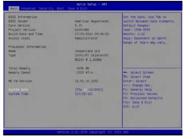
b. Select Advanced- > OEM Configuration->JAHC Enable->Enable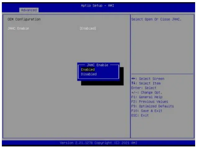
c. Press ‘F10’ to save change & exit after select “JAHC enabled” option.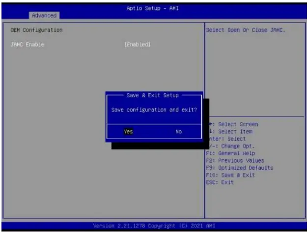
5.2 JAHC software
5.2.1 JAHC software functions
a. RTC wake up. The user can set up automatic startup and shutdown, one week as a circle
b. Caution message prior to shutdown to remind user to save the data. User can also choose to postpone the shutdown process.
c. When JAHC is running, it can support reboot automatically when system is crashed. No additional settings needed.
5.2.2 JAHC software installation guide
System Requirements:
a. Giada player with JAHC function.
b. Switch the JAHC button to “on” or enable it in BIOS if there is no physical button on the chassis.
c. Supported operation system: Windows 10 64bit, Linux 64bit.
How to install JAHC software:
Please download the JAHC.EXE from Giada website: www.giadatech.com, then follow up below steps:
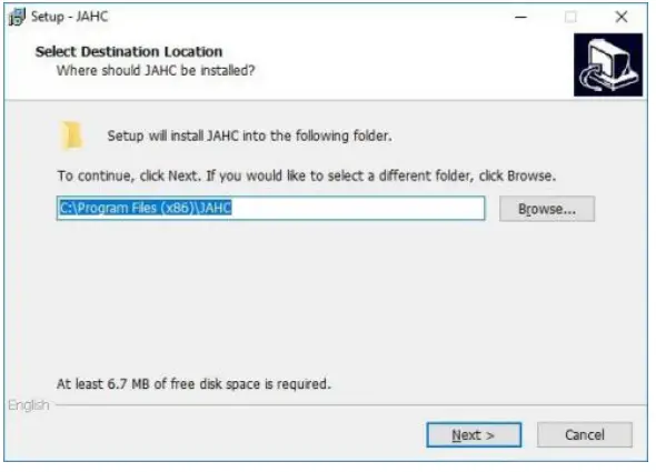
a. Double-click the JAHC.EXE file, the setup wizard will pop up, select destination location and click [Next] button to continue the installation.
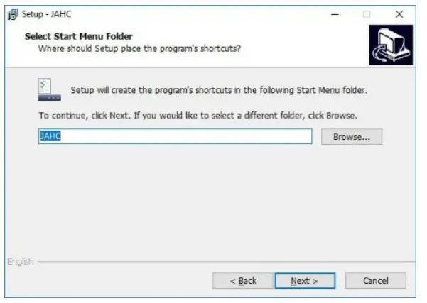
b. Click [Next] button to continue the installation.
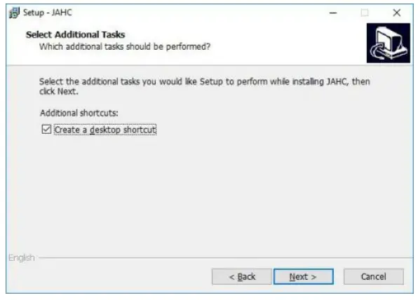
c. Select [Create a desktop shortcut] and click [Next] button.
d. Click [Install] button to continue the installation.
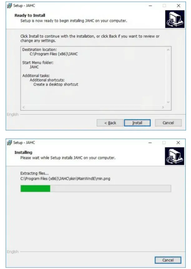
e. Click [Finish] button to finish the installation. You can select [Launch JAHC] to run the software automatically after finishing the installation.
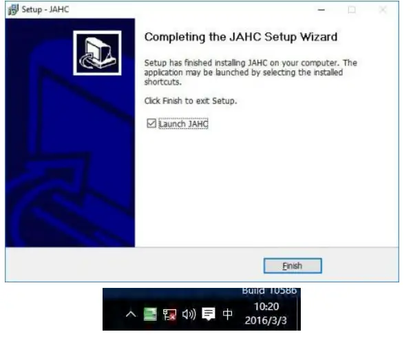
Notice: The JAHC will be added into boot item when it is installed. It will start up when system boot up.
5.2.3 Startup & shutdown time setup
After install the JAHC software, double click the JAHC icon on taskbar and the setup menu will pop up.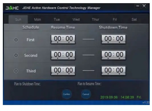
One week as a circle, maximum 3 schedules per day. Select each schedule to set up the resume time and shutdown time. Click [Confirm] button to launch the schedule.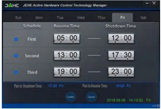
After finishing the setup, the menu window will notice the resume time and shutdown time.![]() Caution: If the interval from shutdown time to next resume time is less than 3 minutes, the system will not shut down.
Caution: If the interval from shutdown time to next resume time is less than 3 minutes, the system will not shut down.
Click [Cancel] button to restore the time settings and cancel the shutdown status.
Click [X] button to hide the menu. You can find it on taskbar.
Right click the JAHC icon on taskbar and select [exit] to exit the software.
Shutdown caution: the shutdown caution will pop up before the system shutdown. You can double click the message window and a new dialog box will pop up.
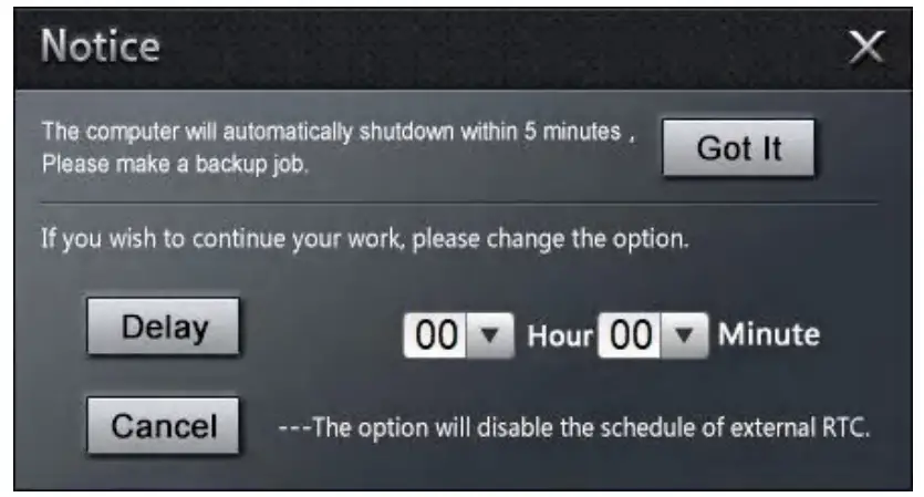
You can click [Delay] button and set up the time to delay the shutdown or click [Cancel] button to cancel the shutdown.
5.3 Watchdog API and instruction
Please contact Giada FAE (email:[email protected]) for watchdog API software and instruction.
Shenzhen JEHE Technology Development Co.. Ltd.
Website: www.giadatech.com
Phone: +86-755-33300336
Email: [email protected]
Address: 1-3/F, Block A. Tsinghua Information Harbor,
North Section Shenzhen Hi-tech Park, Nanshan District Shenzhen, China