Soldering
max. 40W 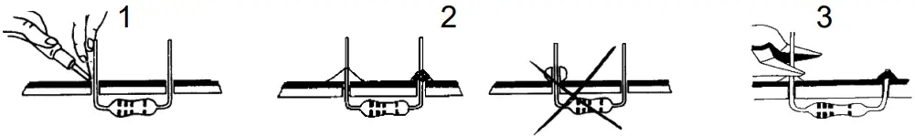
START
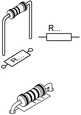
1 Resistor
HWSAH134-23042021
◊ R1…R8, R10…R12, R20 : 100K | (Brown, Black, Yellow)
◊ R9, R15, R19, R21 : 10K | (Brown, Black, Orange)
◊ R13, R14, R17 : 1K | (Brown, Black, Red)
◊ R18 : 1M | (Brown, Black, Green)
◊ R16 : 100 | (Brown, Black, Brown)
◊ R22 : 0 ohm | (Black)
2 DIODE
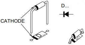
Watch the polarity !
◊ D1, D2 : 1N4148
◊ D3 : 1N4007
3 CAPACITOR
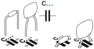
◊ C1 : 3n9 (392)
◊ C2, C3, C4, C5, C6, C7 : 100n (104)
4 PUSHBUTTON
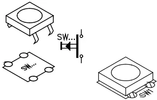
◊ SW1
5 SWITCH
◊ SW2
6 TRANSISTOR
Watch the polarity !
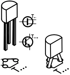
◊ T1, T2 : BC547
◊ T3, T4 : BC557
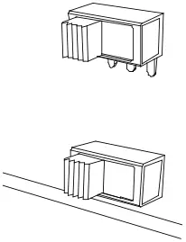
7 PCB TABS
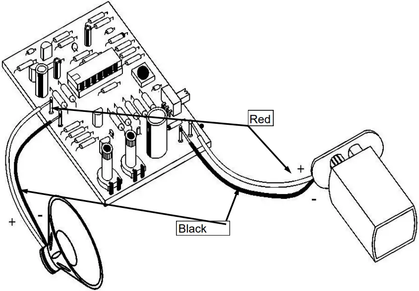
◊ 9 VDC : +/-
◊ speaker : +/-
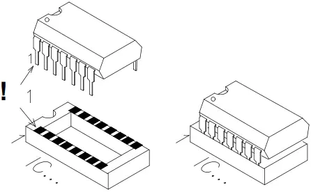
8 IC SOCKET
WATCH THE POSITION OF THE NOTCH !
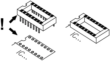
◊ IC1 : 14P
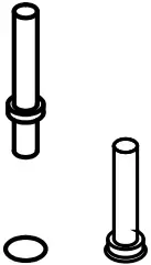
9 ELECTROLYTIC CAPACITOR
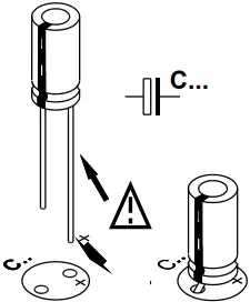
Watch the polarity !
◊ C8, C9 : 10µF
◊ C10, C11 : 470µF
10 TRIMMER
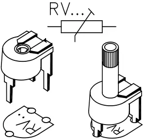
◊ RV1 : 100K
◊ RV2 : 5K (4K7)
11 IC
WATCH THE POSITION OF THE NOTCH !
◊ IC1 : LM324 or eq.
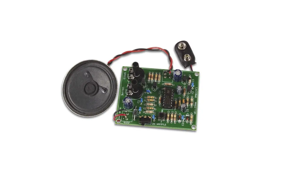
12 SPEAKER & BATTERY
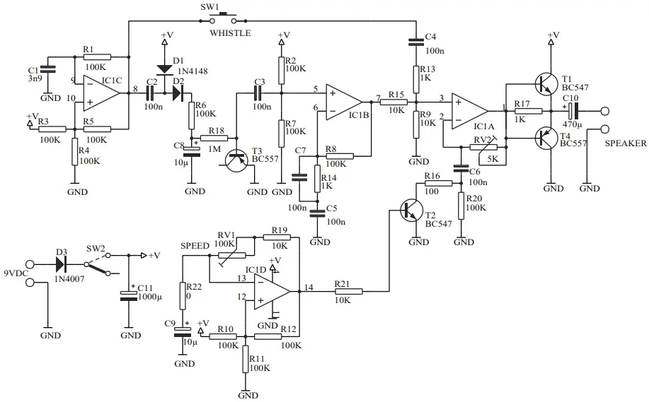
SCHEMATIC DIAGRAM

![]()
TO ALL RESIDENTS OF THE EUROPEAN UNION
Important environmental information about this product
This symbol on this unit or the package, indicates that disposal of this unit after its lifecycle could harm the environment. Do not dispose the unit as unsorted municipal waste; it should be disposed by a specialized company for recycling. This unit should be returned to your distributor or to a local recycling service. Respect the local environmental rules. If any doubt contact your local authorities about waste disposal rules.


