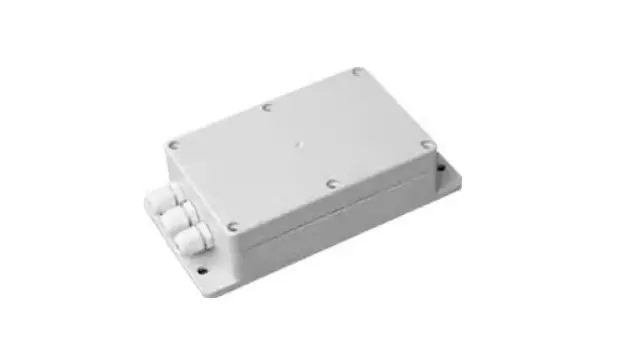
frigicoll FRIAHUKZ-LCAC-02 Inverter Condensing Unit Control Module Owner’s Manual
 IMPORTANT NOTE:
Read this manual carefully before installing or operating your new air conditioning unit. Make sure to save this manual for future reference
Introduction
FRIAHUKZ-LCAC-02 control module enables to control inverter type outdoor unit without the needs of airconditioner factory produced indoor unit. It gives possibility to control outdoor unit capacity and state to produce heat or cooling for AHU or water heater/cooler.
FRIAHUKZ-LCAC-02 control module enables to control inverter condensing unit capacity between 0 – 10%~100% by external input 0~10VDC signal.
Dry contact signal is used to control outdoor unit to work in cooling or heating mode.
The installation and operation of outdoor unit as well controller must be done according to the manuals (i.e. User’s manual, Installation manual, Technical Specification, Service Manual).
Specification and packing list
| Model | FRIAHUKZ-LCAC-02 | |
| Casing | Plastic | |
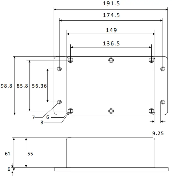
| Dimension (h x w x d) | 61 x100 x191mm | |
| Weight | 0.4KG | |
| Operation Temperature Range | -25 ~ +45 C | |
| Operation Humidity Range | 40-90 % | |
| Power Supply | 230VAC, 1 Phase, 50/60Hz | |
| Voltage Range | 208-240V | |
| Fuse | 15A, 250V | |
| Resistance class | IP54 | |
| Packing list | Box body | 1 piece |
| Box cover | 1 piece | |
| Anti-water seal between box body and box cover | 1 piece | |
| Temp sensor | 1 piece | |
| Gland | 3 pieces | |
| Manual | 1 piece | |
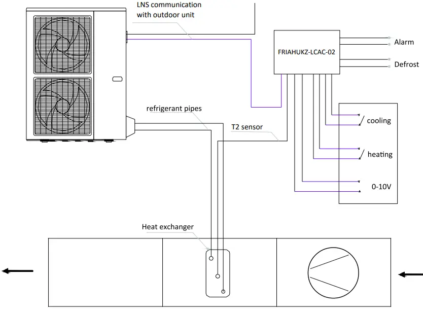
System design
Function and Setting
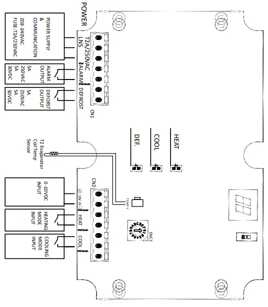
Connection Terminal Introduction
L, N, S—Power Supply and communication with outdoor unit 230V,1-phase, 50Hz. Cable dimension 3×1.0 mm2.
ALARM—digital output 5A-250VAC or 5A-30VDC. When outdoor unit has malfunction signal is activated.
DEFROST—digital output 5A-250VAC or 5A-30VDC. When outdoor unit is in defrost mode is activated.
TEMP1— T2 temp sensor (evaporator coil temperature sensor) terminal. Temp sensor must be placed at middle of heat changer.
0-10V—Analog input terminal to control outdoor unit capacity.
| Analog input | Capacity output | LED display |
| 0-0.5V | 0% | None(Unit stopped) |
| 0.5-1.5V | 10% | digit 1 |
| 1.5-2.5V | 20% | digit 2 |
| 2.5-3.5V | 30% | digit 3 |
| 3.5-4.5V | 40% | digit 4 |
| 4.5-5.5V | 50% | digit 5 |
| 5.5-6.5V | 60% | digit 6 |
| 6.5-7.5V | 70% | digit 7 |
| 7.5-8.5V | 80% | digit 8 |
| 8.5-9.5V | 90% | digit 9 |
| 9.5-10.5V | 100% | digit 10 |
Warning:
Negative(0/-) and Positive(10/+) terminals can not be mixed, otherwise it may destroy this control module. Signal input can not exceed 10.5VDC, otherwise it may destroy this control module.
COOL—Digital input. When terminals are closed, the unit will run in cooling mode and “COOL” LED will be on. Terminal A is Positive(+) and terminal B is Negative(-)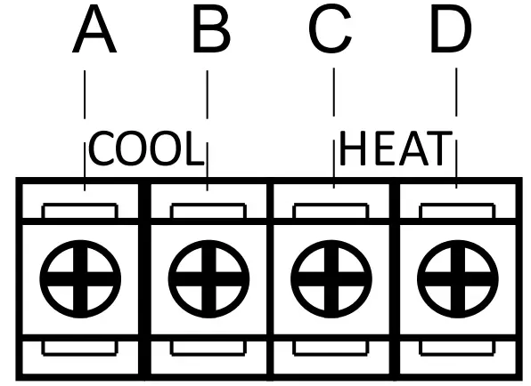
HEAT—Digital input. When terminals are closed, the unit will run in heating mode and “HEAT” LED will be on. Terminal C is Positive(+) and terminal D is Negative(-)
Note: Terminal B and D are connected as one Negative(-), so 3 cables to control cooling/heating are feasible.
ENC1 – knob for multi split connection to select indoor unit capacity. This knob is for multi indoor units connection only. This knob will not work at one indoor to one outdoor connection.
| Knob selection | Indoor unit capacity | Knob selection | Indoor unit capacity |
| 0 | 2,0 kW unit | 6 | 7,1 kW unit |
| 1 | 2,6 kW unit | 7 | 9,0 kW unit |
| 2 | 3,2kW unit | 8 | 10,5 kW unit |
| 3 | 3,5 kW unit | 9 | 14,0 kW unit |
| 4 | 5,3 kW unit | A-F | 16,0 kW unit |
| 5 | 7,1 kW unit |
LED lamps introduction
HEAT LED is lightened when the unit is operating in heating mode.
COOL LED is lightened when the unit is operating in cooling mode.
DEF LED is lightened when unit is in defrost mode
Malfunction and Error Code
| Error Code | Malfunction or Protection |
| E1 | communication error with outdoor unit. |
| E5 | evaporator coil temperature sensor T2 malfunction |
| F0 | current overload protection |
| F1 | outdoor unit ambient temperature sensor T4 malfunction |
| F2 | outdoor unit condenser pipe temperature sensor T3 malfunction |
| F3 | outdoor unit compressor discharge temperature sensor TP malfunction |
| F4 | outdoor unit EEPROM parameter error |
| F5 | outdoor unit fan speed is operating outside of the normal range |
| F6 | outdoor unit T2b temperature sensor malfunction |
| P0 | IPM malfunction or IGBT over-strong current protection |
| P1 | over voltage or over low voltage protection |
| P2 | top temperature protection of compressor |
| P3 | outdoor low temperature protection |
| P4 | compressor protection or malfunction |
| — | multi split indoor units cooling/heating mode conflict |
| P6 | low pressure protection of compressor |
For troubleshooting, please refer to outdoor unit factory technical manual and solution.
Dimensions (mm)
Appendix 1 Temperature Sensor Resistance Value Table (°C–K)
| °C | K Ohm | °C | K Ohm | °C | K Ohm | °C | K Ohm |
| -20 | 115.266 | 20 | 12.6431 | 60 | 2.35774 | 100 | 0.62973 |
| -19 | 108.146 | 21 | 12.0561 | 61 | 2.27249 | 101 | 0.61148 |
| -18 | 101.517 | 22 | 11.5000 | 62 | 2.19073 | 102 | 0.59386 |
| -17 | 96.3423 | 23 | 10.9731 | 63 | 2.11241 | 103 | 0.57683 |
| -16 | 89.5865 | 24 | 10.4736 | 64 | 2.03732 | 104 | 0.56038 |
| -15 | 84.2190 | 25 | 10.000 | 65 | 1.96532 | 105 | 0.54448 |
| -14 | 79.3110 | 26 | 9.55074 | 66 | 1.89627 | 106 | 0.52912 |
| -13 | 74.5360 | 27 | 9.12445 | 67 | 1.83003 | 107 | 0.51426 |
| -12 | 70.1698 | 28 | 8.71983 | 68 | 1.76647 | 108 | 0.49989 |
| -11 | 66.0898 | 29 | 8.33566 | 69 | 1.70547 | 109 | 0.48600 |
| -10 | 62.2756 | 30 | 7.97078 | 70 | 1.64691 | 110 | 0.47256 |
| -9 | 58.7079 | 31 | 7.62411 | 71 | 1.59068 | 111 | 0.45957 |
| -8 | 56.3694 | 32 | 7.29464 | 72 | 1.53668 | 112 | 0.44699 |
| -7 | 52.2438 | 33 | 6.98142 | 73 | 1.48481 | 113 | 0.43482 |
| -6 | 49.3161 | 34 | 6.68355 | 74 | 1.43498 | 114 | 0.42304 |
| -5 | 46.5725 | 35 | 6.40021 | 75 | 1.38703 | 115 | 0.41164 |
| -4 | 44.0000 | 36 | 6.13059 | 76 | 1.34105 | 116 | 0.40060 |
| -3 | 41.5878 | 37 | 5.87359 | 77 | 1.29078 | 117 | 0.38991 |
| -2 | 39.8239 | 38 | 5.62961 | 78 | 1.25423 | 118 | 0.37956 |
| -1 | 37.1988 | 39 | 5.39689 | 79 | 1.21330 | 119 | 0.36954 |
| 0 | 35.2024 | 40 | 5.17519 | 80 | 1.17393 | 120 | 0.35982 |
| 1 | 33.3269 | 41 | 4.96392 | 81 | 1.13604 | 121 | 0.35042 |
| 2 | 31.5635 | 42 | 4.76253 | 82 | 1.09958 | 122 | 0.3413 |
| 3 | 29.9058 | 43 | 4.57050 | 83 | 1.06448 | 123 | 0.33246 |
| 4 | 28.3459 | 44 | 4.38736 | 84 | 1.03069 | 124 | 0.32390 |
| 5 | 26.8778 | 45 | 4.21263 | 85 | 0.99815 | 125 | 0.31559 |
| 6 | 25.4954 | 46 | 4.04589 | 86 | 0.96681 | 126 | 0.30754 |
| 7 | 24.1932 | 47 | 3.88673 | 87 | 0.93662 | 127 | 0.29974 |
| 8 | 22.5662 | 48 | 3.73476 | 88 | 0.90753 | 128 | 0.29216 |
| 9 | 21.8094 | 49 | 3.58962 | 89 | 0.87950 | 129 | 0.28482 |
| 10 | 20.7184 | 50 | 3.45097 | 90 | 0.85248 | 130 | 0.27770 |
| 11 | 19.6891 | 51 | 3.31847 | 91 | 0.82643 | 131 | 0.27078 |
| 12 | 18.7177 | 52 | 3.19183 | 92 | 0.80132 | 132 | 0.26408 |
| 13 | 17.8005 | 53 | 3.07075 | 93 | 0.77709 | 133 | 0.25757 |
| 14 | 16.9341 | 54 | 2.95896 | 94 | 0.75373 | 134 | 0.25125 |
| 15 | 16.1156 | 55 | 2.84421 | 95 | 0.73119 | 135 | 0.24512 |
| 16 | 15.3418 | 56 | 2.73823 | 96 | 0.70944 | 136 | 0.23916 |
| 17 | 14.6181 | 57 | 2.63682 | 97 | 0.68844 | 137 | 0.23338 |
| 18 | 13.9180 | 58 | 2.53973 | 98 | 0.66818 | 138 | 0.22776 |
| 19 | 13.2631 | 59 | 2.44677 | 99 | 0.64862 | 139 | 0.22231 |
Oficina Central Blasco
de Garay, 4-6 08960
Sant Just Desvern
Barcelona Tel: +34 93 480 33 22
http://www.frigicoll.es
Frigicoll France SARL
Parc Silic-Immeuble Panama 45 rue de Villeneuve 94150 Rungis
Tel. +33 9 80 80 15 14
http://www.frigicoll.es/fr