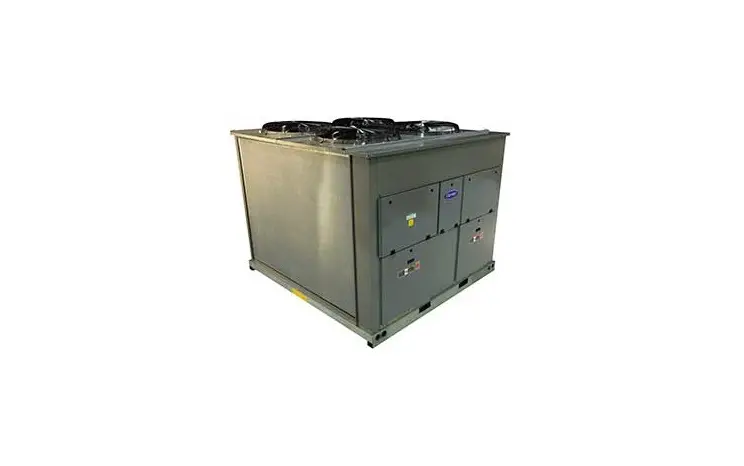
Carrier 38APD 025-130 Air Cooled Condensing Unit Instruction Manual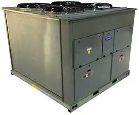
SAFETY CONSIDERATIONS
Installation and servicing of air-conditioning equipment can be hazardous due to system pressure and electrical components. Only trained and qualified service personnel should install, repair, or service air-conditioning equipment.
Untrained personnel can perform basic maintenance functions of cleaning coils and filters and replacing filters. All other operations should be performed by trained service personnel. When working on air-conditioning equipment, observe precautions in the literature, tags and labels attached to the unit, and other safety precautions that may apply.
Follow all safety codes. Wear safety glasses and work gloves. Use quenching cloth for unbrazing operations. Have fire extinguisher available for all brazing operations.
It is important to recognize safety information. This is the safetyalert symbol . ![]() When you see this symbol on the unit and in instructions or manuals, be alert to the potential for personal injury.
When you see this symbol on the unit and in instructions or manuals, be alert to the potential for personal injury.
Understand the signal words DANGER, WARNING, CAUTION, and NOTE. These words are used with the safety-alert symbol.
DANGER identifies the most serious hazards which will result in severe personal injury or death. WARNING signifies hazards which could result in personal injury or death. CAUTION is used to identify unsafe practices, which may result in minor personal injury or product and property damage. NOTE is used to highlight suggestions which will result in enhanced installation, reliability, or operation.
Table 1 — Product Usage
| UNIT | ACCESSORY PART NO. | QTY |
| 38APD 025-100 |
30RA-900—005 | 1 |
| 38APD 115-130 38APS 025-065 09DPM 035-95 | 2 1 1 | |
| 09DPM 115-130 | 2 | |
| 09DPS 018-030 | 1 | |
| 30MPA 020-071 | 30MP-900—003 | 1 |
| 30MPA 020-071 with | 2 | |
| Height Adjustment Accessory | ||
| 30MPE | 1 | |
| 30MPE with Height Adjustment Accessory | 2 | |
| 30MPW 016-071 | 1 | |
| 30MPW016-071 with Height Adjustment Accessory | 2 | |
| 30RAP 010-090 30RAP 115-130 | 30RA-900—005 | 1 2 |
GENERAL
Multiple accessory packages may be required depending on product, see Table 1 for accessory package selection. Each vibration isolation accessory package consists of 4 resilient neoprene pads Refer to Table 2. The pads are oil-resistant and have a ribbed design. (See Fig. 1 and 2.)
PRE-INSTALLATION
Remove accessory from packaging and inspect shipment for damage. File claim with shipping company if accessory is damaged or incomplete.
INSTALLATION
The accessory kit is usually installed at the initial unit installation.
If the kit is to be installed after the unit is already in place, disconnect all power, chilled fluid piping, and refrigerant piping to the unit first.
![]() WARNING
WARNING
Electrical shock can cause personal injury and death. Shut off all power to this equipment during installation. There may be more than one disconnect switch. Tag all disconnect locations to alert others not to restore power until work is completed.
Install the accessory kit as follows:
- Rig unit per base unit installation instructions and raise unit above its final installation location (see Fig. 3-5).
- Locate pads at mounting points as shown in Fig. 6.
- Lower unit in place. Note that unit must be leveled according to base unit installation instructions.
- Restore unit power and piping connections or continue with initial unit installation.
Table 2 — Package Contents
| PART NO. DESCRIPTION | VIRBATION PAD PART NO. | PAD DIMENSIONS in. (mm) | QTY |
| 30MP-900—003 | 2004386152 | 3.5×3.5×1/4 (89x89x6) | 4 |
| 30RA-900—005 | 30GX501130 | 24x3x1/4 (610x76x6) | 4 |
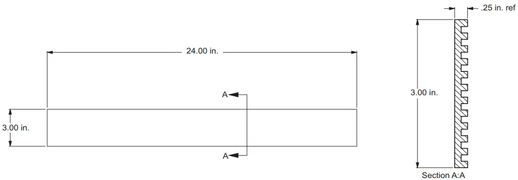
Fig. 1 — Vibration Isolation Pad Dimensions (30RA-900- – -005)
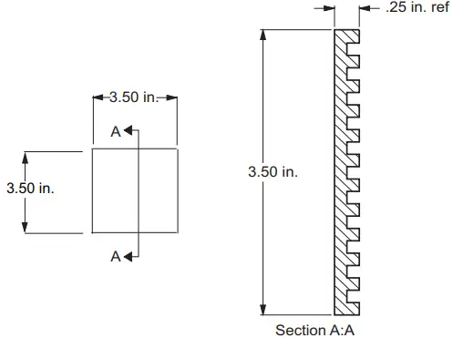
Fig. 2 — Vibration Isolation Pad Dimensions (30MP-900- – -003)
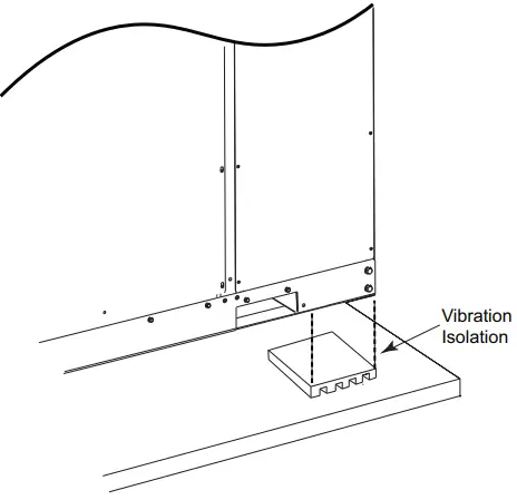
Fig. 3 — 30MP Typical Installation
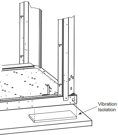
Fig. 4 — 38AP, 09DP, and 30RAP Typical Installation
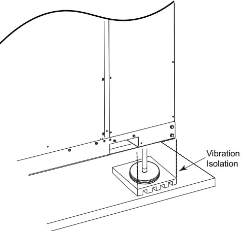
Fig. 5 — 30MP with Height Adjustment Typical Installation
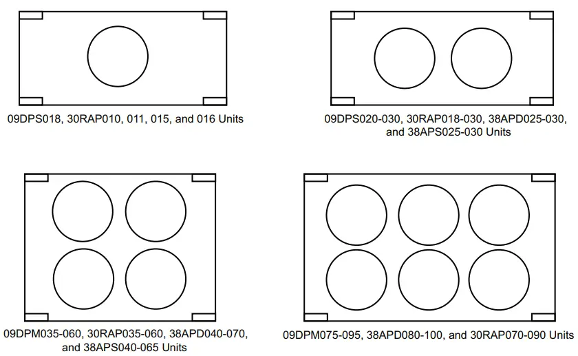
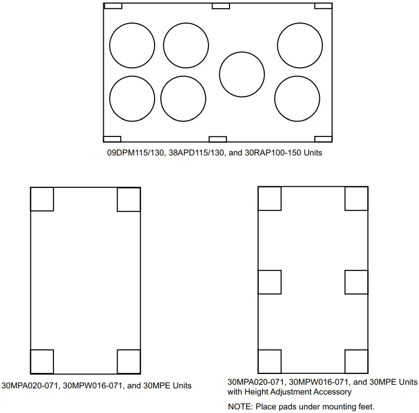
Fig. 6 — Vibration Isolation Pad Locations


 Isotwin Condens Instruction Manual")


