![]() AMK P SERIES R32 Non Inverter Air Conditioners
AMK P SERIES R32 Non Inverter Air Conditioners
Instruction Manual
AMK P
SERIES R32
INSTALLATION AND TECHNICAL SERVICE INSTRUCTIONS
MK P
Dear Technician,
We would like to congratulate you on having recommended a R unit: a modern product that is capable of ensuring maximum comfort at length, with a high degree of reliability, efficiency, quality and safety.
While your technical skills and knowledge will certainly be more than sufficient, this booklet contains all the information that we have deemed necessary for the device’s correct and easy installation.
Thank you again, and keep up the good work.
COMPLIANCE
![]() R AMK P heat pumps are compliant with the following European Directives:
R AMK P heat pumps are compliant with the following European Directives:
——Low Voltage Directive 2014/35/EU
——Electromagnetic Compatibility Directive 2014/30/EU
——RoHS Directive 2011/65/EU
——ErP Directive 2009/125/EC and Regulation 2012/206/EC
——WEEE Directive 2012/19/EU
——F-Gas Regulation 2014/517/EU
RANGE
| Model | Code |
| AMK 100 P | 20158940 |
| AMK 125 P | 20158941 |
| AMK 140 P | 20158942 |
| 4 ways panel for AMK 70-140 P | 20151433 |
ACCESSORIES
For the complete list of accessories and the information relating to their usage combinations, please refer to the catalogue.
The following symbols are used on the product:![]() The R32 refrigerant gas is slightly inflammable and odourless. Avoid proximity to sources of ignition in continuous operation (open flames, gas household appliances, electric stoves, lit cigarettes, etc).
The R32 refrigerant gas is slightly inflammable and odourless. Avoid proximity to sources of ignition in continuous operation (open flames, gas household appliances, electric stoves, lit cigarettes, etc).![]() For more information, see the installation and technical service instructions.
For more information, see the installation and technical service instructions.![]() Before performing maintenance and service tasks, read the installation and technical service instructions.
Before performing maintenance and service tasks, read the installation and technical service instructions.![]() Before the installation, read the installation and technical service instructions.
Before the installation, read the installation and technical service instructions.
The following symbols are used in this publication:![]() WARNING = actions requiring special care and appropriate training.
WARNING = actions requiring special care and appropriate training.![]() DO NOT = actions that MUST ON NO ACCOUNT be carried out.
DO NOT = actions that MUST ON NO ACCOUNT be carried out.
GENERAL INFORMATION
1.1 General Notices![]() When you get the product, check immediately that the contents are all present and undamaged. Contact the dealer R if you notice any problems.
When you get the product, check immediately that the contents are all present and undamaged. Contact the dealer R if you notice any problems.![]() The product’ s installation must be carried out by an authorised company that will issue a declaration of the installation’s conformity to the product’s owner once the work has been completed, indicating that the work has been carried out in accordance with the standards of good practice, current National and Local regulations, and the indications provided by R in the instruction booklet accompanying the device.
The product’ s installation must be carried out by an authorised company that will issue a declaration of the installation’s conformity to the product’s owner once the work has been completed, indicating that the work has been carried out in accordance with the standards of good practice, current National and Local regulations, and the indications provided by R in the instruction booklet accompanying the device.![]() The R32 refrigerant gas is slightly inflammable and odourless. Carefully read the safety data sheet available from the dealer and see table “Minimum floor area for ceiling installation” p. 9.
The R32 refrigerant gas is slightly inflammable and odourless. Carefully read the safety data sheet available from the dealer and see table “Minimum floor area for ceiling installation” p. 9.![]() The product must be used for its intended purpose, as stated by R for which it has been expressly manufactured. R shall bear no responsibility, whether of a contractual or non-contractual nature, for any damage caused to people, animals, or property due to incorrect installation, adjustments, or maintenance, or improper use.
The product must be used for its intended purpose, as stated by R for which it has been expressly manufactured. R shall bear no responsibility, whether of a contractual or non-contractual nature, for any damage caused to people, animals, or property due to incorrect installation, adjustments, or maintenance, or improper use.![]() Suitable clothing, instrumentation, and accident-prevention devices must be utilized during the installation and/ or maintenance operations. R shall bear no responsi bility for any failure to comply with current safety and accident-prevention regulations.
Suitable clothing, instrumentation, and accident-prevention devices must be utilized during the installation and/ or maintenance operations. R shall bear no responsi bility for any failure to comply with current safety and accident-prevention regulations.![]() During installation and/or service operations, keep the area around the unit tidy and clean.
During installation and/or service operations, keep the area around the unit tidy and clean.![]() Comply with the legislation in force on the country of deployment with regard to the use and disposal of packaging, of cleaning and maintenance products and for the man- agement of the unit’s decommissioning.
Comply with the legislation in force on the country of deployment with regard to the use and disposal of packaging, of cleaning and maintenance products and for the man- agement of the unit’s decommissioning.![]() Any repair and maintenance interventions must be carried out by R Technical Support Service, in accordance with the provisions contained in this publication. Do not modify or tamper with the unit as dangerous situations may arise and the unit manufacturer will not be liable for any damage caused.
Any repair and maintenance interventions must be carried out by R Technical Support Service, in accordance with the provisions contained in this publication. Do not modify or tamper with the unit as dangerous situations may arise and the unit manufacturer will not be liable for any damage caused.![]() In the event of any functional anomalies or fluid leaks, set the system’s main switch to its “off” position. Promptly con- tact your local R Technical Support Service, and do not perform any interventions upon the device on your own.
In the event of any functional anomalies or fluid leaks, set the system’s main switch to its “off” position. Promptly con- tact your local R Technical Support Service, and do not perform any interventions upon the device on your own.![]() The units contain refrigerant gas: operate carefully so as to avoid damaging the gas circuit and the fin bank.
The units contain refrigerant gas: operate carefully so as to avoid damaging the gas circuit and the fin bank.![]() Any gas leaks indoors can generate toxic gases if they come into contact with naked flames or high temperature bodies, in case of leaks, please air the rooms thoroughly.
Any gas leaks indoors can generate toxic gases if they come into contact with naked flames or high temperature bodies, in case of leaks, please air the rooms thoroughly.![]() Do not place any inflammable object (spray cans) within a 1 metre radius from the air expulsion.
Do not place any inflammable object (spray cans) within a 1 metre radius from the air expulsion.![]() According to EU Regulation no. 517/2014 regarding certain fluorinated greenhouse gases, the total amount of refrig- erant contained within the installed system must be indi- cated. This information can be found on the unit technical data plate.
According to EU Regulation no. 517/2014 regarding certain fluorinated greenhouse gases, the total amount of refrig- erant contained within the installed system must be indi- cated. This information can be found on the unit technical data plate.![]() This unit contains fluorinated greenhouse gases covered by the Kyoto protocol. Maintenance and disposal activities must be carried out exclusively by skilled personnel.
This unit contains fluorinated greenhouse gases covered by the Kyoto protocol. Maintenance and disposal activities must be carried out exclusively by skilled personnel.![]() This booklet is an integral part of the device, and must therefore be carefully preserved, and must ALWAYS accompany it, even in the event that it is sold to another Owner or User, or is transferred to another system. If it is damaged or lost, another copy can be requested to R Technical Support Service in your Area.
This booklet is an integral part of the device, and must therefore be carefully preserved, and must ALWAYS accompany it, even in the event that it is sold to another Owner or User, or is transferred to another system. If it is damaged or lost, another copy can be requested to R Technical Support Service in your Area.
1.2 Safety precautions
It should be noted that the use of products that utilize electric energy requires certain essential safety regulations to be re- spected, including the following:
![]() Do not allow children or unassisted disabled people to use the unit.
Do not allow children or unassisted disabled people to use the unit.![]() Do not touch the unit while barefoot and/or partially wet.
Do not touch the unit while barefoot and/or partially wet.![]() Do not spray or throw water directly on the unit.
Do not spray or throw water directly on the unit.![]() It is strictly forbidden to touch the coil fins, the moving parts, to place any body parts between them, or to insert pointy objects into the grilles.
It is strictly forbidden to touch the coil fins, the moving parts, to place any body parts between them, or to insert pointy objects into the grilles.![]() It is forbidden to perform any technical interventions or cleaning operations before having disconnected the de- vice from its electrical power supply, by setting the system’s main switch to its “OFF” position.
It is forbidden to perform any technical interventions or cleaning operations before having disconnected the de- vice from its electrical power supply, by setting the system’s main switch to its “OFF” position.![]() It is forbidden to modify the safety or regulation devices without the authorisation of the manufacturer.
It is forbidden to modify the safety or regulation devices without the authorisation of the manufacturer.![]() Do not pull, detach or twist the electrical wires coming out of the unit, even when the unit is disconnected from the power grid.
Do not pull, detach or twist the electrical wires coming out of the unit, even when the unit is disconnected from the power grid.![]() The packing material must not be disposed of in the surrounding environment and must be kept out of children reach, as it can be dangerous. It must be disposed of according to the regulations in force.
The packing material must not be disposed of in the surrounding environment and must be kept out of children reach, as it can be dangerous. It must be disposed of according to the regulations in force.
R AMK P is an indoor unit for ceiling installation, suitable for use in commercial applications in combination with AARIA PRO P R32 and AARIA PRO R410A outdoor units. The multiple-speed fan DC motor improves performance and sound comfort.
Control, regulation and programming of the unit are carried out by means of the infra-red remote control, whose functions and use are detailed in the user manual.
1.4 Safety and adjustment devices
The device safety and setting are achieved thanks to:
——heat exchanger temperature sensor transmitting the de- tected value to the control panel, which is trigged in case of abnormal temperature with regard to the operating mode
——room air temperature sensor transmitting the detected value to the control panel in order to control the operation of the outdoor unit and regulate the room temperature![]() Safety device replacement must be carried out by R Technical Support Service, using only original components.
Safety device replacement must be carried out by R Technical Support Service, using only original components.
Please refer to the spare parts catalogue.![]() IT IS FORBIDDEN to operate the device with faulty safety systems.
IT IS FORBIDDEN to operate the device with faulty safety systems.
1.5 Identification
The unit can be identified through the technical data plate: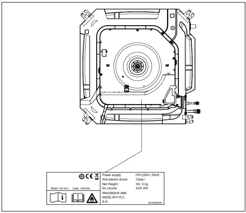 Technical data plate
Contains the device’s technical and performance data.![]() The tampering, removal, or absence of the identification plates will not allow the product to be properly identified by its serial number.
The tampering, removal, or absence of the identification plates will not allow the product to be properly identified by its serial number.
1.6 Layout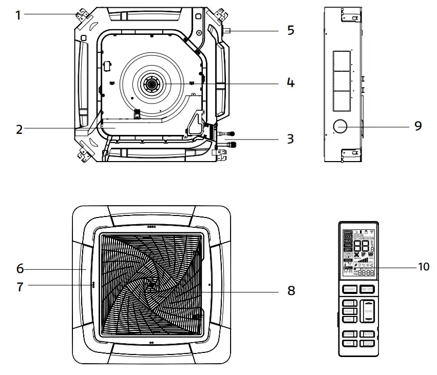
| 1 Support bracket 2 Electric panel cover 3 Refrigerant connections 4 Fan 5 Condensation discharge | 6 Motor-driven deflectors 7 Display 8 Air intake grille 9 Fresh air hole 10 Remote control |
1.7 Technical specifications
| Model | 100 P | 125 P | 140 P | |
| Electrical characteristics | ||||
| Power supply 230/1/50 | V/Ph/Hz | |||
| Fan | ||||
| Quantity | 1 | 1 | 1 | no. |
| Nominal, power input | 1,34 | 1,20 | 1,20 | IWV |
| Nominal current consumption | 0,45 | 0,50 | 0,52 | A |
| Maximum air flow | 1680 | 1950 | 1950 | m3/h |
| Medium airflow | 1530 | 1600 | 1600 | m3/h |
| Minimum air flow | 1320 | 1440 | 1440 | m3/h |
| Superminimum airflow | 1190 | 1200 | 1200 | m3/h |
| Maximum speed | 650 | 750 | 750 | rpm |
| Medium speed | 550 | 650 | 650 | rpm |
| Minimum speed | 450 | 500 | 500 | rpm |
| Super minimum speed | 400 | 400 | 400 | rpm |
| Cooling sound levels | ||||
| Superminimum sound pressure | 34 | 34 | 34 | dB(A) |
| Minimum sound pressure | 38 | 38 | 38 | dB(A) |
| Medium sound pressure | 42 | 44 | 43 | dB(A) |
| Maximum sound pressure | 45 | 47 | 47 | dB(A) |
| Maximum sound power | 62 | 64 | 64 | dB(A) |
| Heating sound levels | ||||
| Superminimum sound pressure | 34 | 34 | 34 | dB(A) |
| Minimum sound pressure | 38 | 38 | 38 | dB(A) |
| Medium sound pressure | 42 | 44 | 43 | dB(A) |
| Maximum sound pressure | 45 | 47 | 46 | dB(A) |
| Maximum sound power | 62 | 64 | 64 | dB(A) |
![]() Performance data are indicated in the matching outdoor unit manual.
Performance data are indicated in the matching outdoor unit manual.
1.8 Cooling circuit
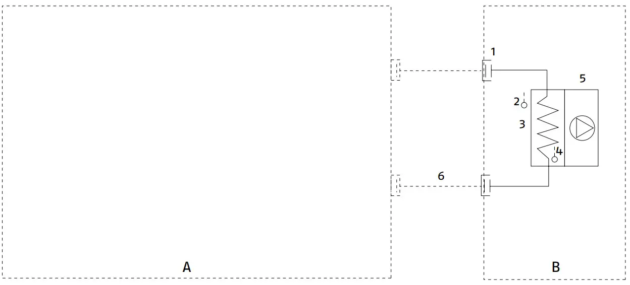
A Outdoor unit
B Indoor unit
- Refrigerant connections
- Room air probe
- Heat exchanger
- Heat exchanger sensor
- Electric fan
- Connection pipes
INSTALLATION
Ensure that the installation and operation sites are properly ventilated in order to disperse any gas leaks that could cause flames during activities with intense heat generation and high temperature.![]() Avoid proximity to sources of ignition in continuous operation (open flames, gas household appliances, electric stoves, lit cigarettes, etc).
Avoid proximity to sources of ignition in continuous operation (open flames, gas household appliances, electric stoves, lit cigarettes, etc).![]() Use equipment suitable for the system refrigerant.
Use equipment suitable for the system refrigerant.![]() Use an electronic leak finder properly calibrated for the system refrigerant.
Use an electronic leak finder properly calibrated for the system refrigerant.![]() It is forbidden to use leak finders with halogen lamps.
It is forbidden to use leak finders with halogen lamps.
2.1 Receiving the product
R AMK P is supplied in a single package, protected by a cardboard packaging, polystyrene elements and a polyethylene film.
The following items can be found inside the packaging:
Document envelope:
——Instruction’s book for the installer and for the Technical Service in Italian
——Instruction’s book for the installer and for the Technical Service in English
——user instruction booklet in Italian
——user instruction booklet in English
——Warranty/Spare parts labels.
——contact sheets It is also supplied as kit:
——remote control
——no. 2 AAA batteries
——4 screws
——flare nut for liquid pipe
——flare nut for gas pipe
——insulating material
——clamps
——hose clamp
——condensate discharge pipe![]() The Instruction book comes with the equipment and it should be taken, read and kept carefully.
The Instruction book comes with the equipment and it should be taken, read and kept carefully.![]() The document envelope must be kept in a safe place. Any duplicate must be requested from Riello S.p.A. which reserves to charge the cost.
The document envelope must be kept in a safe place. Any duplicate must be requested from Riello S.p.A. which reserves to charge the cost.
2.2 Labels positioning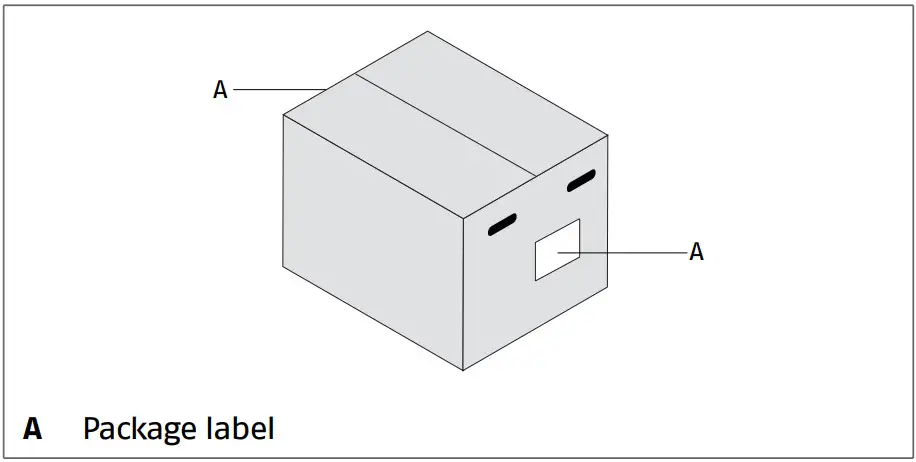
2.3 Dimensions and weight
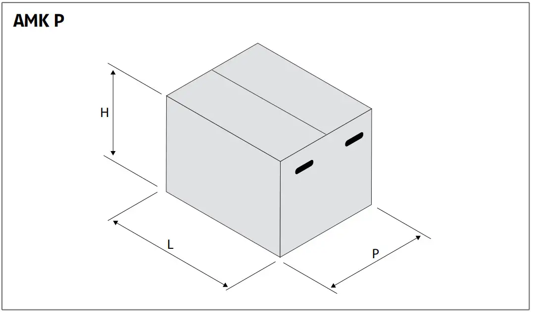
| Model | 100 P | 125 P | 11+0 P | |
| Packaging dimensions | ||||
| H | 310 | 380 | 380 | mm |
| L | 990 | 990 | 990 | mm |
| P | 990 | 990 | 990 | mm |
| Weight | 36,0 | 38,0 | 38,0 | kg |
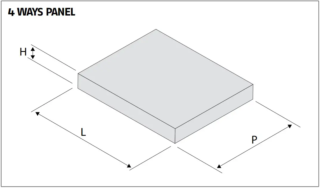
| Model | 70 – 140 | |
| Packaging dimensions | ||
| L | 980 | mm |
| P | 980 | mm |
| H | 100 | mm |
| Weight | 9,0 | kg |
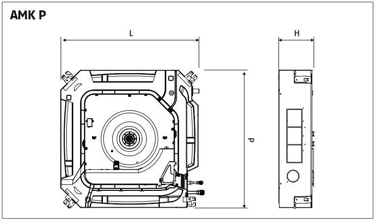
| Model | 100 P | 125 P | 140 P | |
| Product dimensions | ||||
| H | 246 | 288 | 288 | mm |
| 840 | 840 | 840 | mm | |
| 840 | 840 | 840 | mm | |
| Weight | 31,0 | 32,0 | 32,0 | kg |
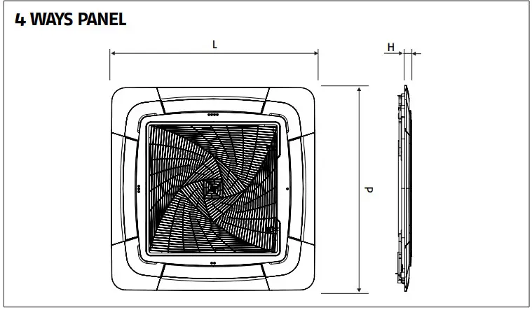
| Model | 70 – 140 | |
| Product dimensions | ||
| L | 950 | mm |
| P | 950 | mm |
| H | 50 | mm |
| Weight | 6,5 | kg |
2.4 Storage![]() The product must be stored of according to the regulations in force.
The product must be stored of according to the regulations in force.
2.5 Handling and removal of the packing
Before unpacking, personal protective clothing should be worn and used transport means and tools suitable for the size and weight of the unit. The product can be handled manually.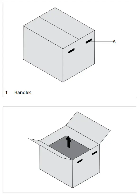
Follow the below instructions for packing removal and product handling:
- transport the equipment in the installation place
- open the cardboard packaging
- remove the document envelope
- take out the device by lifting it up
- remove the polystyrene elements
- remove the polyethylene bag
 In manual operation it is compulsory to respect always the maximum weight per person provided for by the national laws and standards.Handle with careThe packing material must not be disposed of in the sur- rounding environment and must be kept out of children reach, as it can be dangerous. It must be disposed of ac- cording to the regulations in force.
2.6 Place of installation
The location of RIELLO AMK P devices must be determined by the system’s designer or by another competent person, and must take into account the technical requirements, as well as any current local regulations.![]() The product uses R32 refrigerant gas and must be installed in rooms with a minimum floor area, as indicated in the following table, depending on the total refrigerant charge of the system (given by the sum of the factory charge of the outdoor unit and, if appicable, the additional charge).
The product uses R32 refrigerant gas and must be installed in rooms with a minimum floor area, as indicated in the following table, depending on the total refrigerant charge of the system (given by the sum of the factory charge of the outdoor unit and, if appicable, the additional charge).![]() The amount of refrigerant charged inside the unit refer to the INSTALLATION AND TECHNICAL SERVICE INSTRUCTIONS of out- door unit used.
The amount of refrigerant charged inside the unit refer to the INSTALLATION AND TECHNICAL SERVICE INSTRUCTIONS of out- door unit used.
Minimum floor area for ceiling installation
| int | A min | mc | A min |
| kg | m2 | kg | m2 |
| 0,2 | 2,1 | 2,81 | |
| 0,6 | 2,2 | 3,09 | |
| 0,8 | 2,3 | 3,38 | |
| No requirements | |||
| 1,0 | 2,4 | 3,68 | |
| 1,1 | 2,5 | 3,99 | |
| 1,224 | 2,6 | 4,31 | |
| 1,225 | 0,96 | 2,8 | 5,00 |
| 1,3 | 1,08 | 3,0 | 5,74 |
| 1,4 | 1,25 | 3,4 | 7,38 |
| 1,5 | 1,44 | 3,8 | 9,22 |
| 1,6 | 1,63 | 4,2 | 11,26 |
| 1,7 | 1,84 | 4,6 | 13,50 |
| 1,8 | 2,07 | 5,0 | 15,96 |
| 1,9 | 2,30 | 5,4 | 18,61 |
| 2,0 | 2,55 | 5,8 | 21,47 |
mc:refrigerant charge of the system
A min:minimum floor area for indoor unit
RIELLO AMK P is designed for indoor on false-ceilin installation:
- install the indoor unit in the room to be air-conditioned
- its position must allow for the circulation of treated air in the whole room
- consider an area where there are no obstacles to the reg- ular air delivery and intake
Check that: - the support wall is able to support the device weight
- the wall section does not feature building supporting ele- ments, pipes or power lines
Avoid:
- installing the device in hallways or passageways
- any obstacles or barriers that will cause the expelled air to recirculate
- locations with aggressive or explosive atmospheres or with inflammable fluids
- direct exposure to sunlight and proximity to heat sources
- humid locations or positions where the unit could come into contact with water
- environment containing oil vapours
- locations with high frequency contamination
![]() Avoid placing the unit less than 1 metre away from radio and video systems.
Avoid placing the unit less than 1 metre away from radio and video systems.![]() A detachable section cut into the suspended ceiling is re- quired in order to access the unit.
A detachable section cut into the suspended ceiling is re- quired in order to access the unit.
2.7 Recommended distances
The distances for the device installation and maintenance are shown in the figure. The indicated spaces are necessary in order to prevent the airflow from being blocked, as well as to allow normal cleaning and maintenance operations to be carried out.
Installation
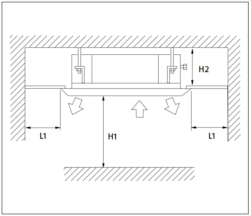
| Model | 100 P | 125 P 140 P | |
| Spacing distance | |||
| L1 | 500 | mm | |
| H1 | 2500 | mm | |
| H2 | 246 | 288 | mm |
2.8 Installation on old systems or systems in need of upgrading
When R AMK P is installed on old systems or systems in need of upgrading, it is recommended to ensure that:
——the electrical system is compliant with the applicable regulations and has been installed by qualified professionals![]() In the event of a replacement, the system must be inspected by the designer or by another competent person, and must be compliant with the technical requirements, as well as the current legislations and regulations.
In the event of a replacement, the system must be inspected by the designer or by another competent person, and must be compliant with the technical requirements, as well as the current legislations and regulations.![]() The manufacturer shall bear no responsibility for any dam- ages caused by incorrect system installation.
The manufacturer shall bear no responsibility for any dam- ages caused by incorrect system installation.
2.9 Positioning
R AMK P units are supplied with a paper template for installation: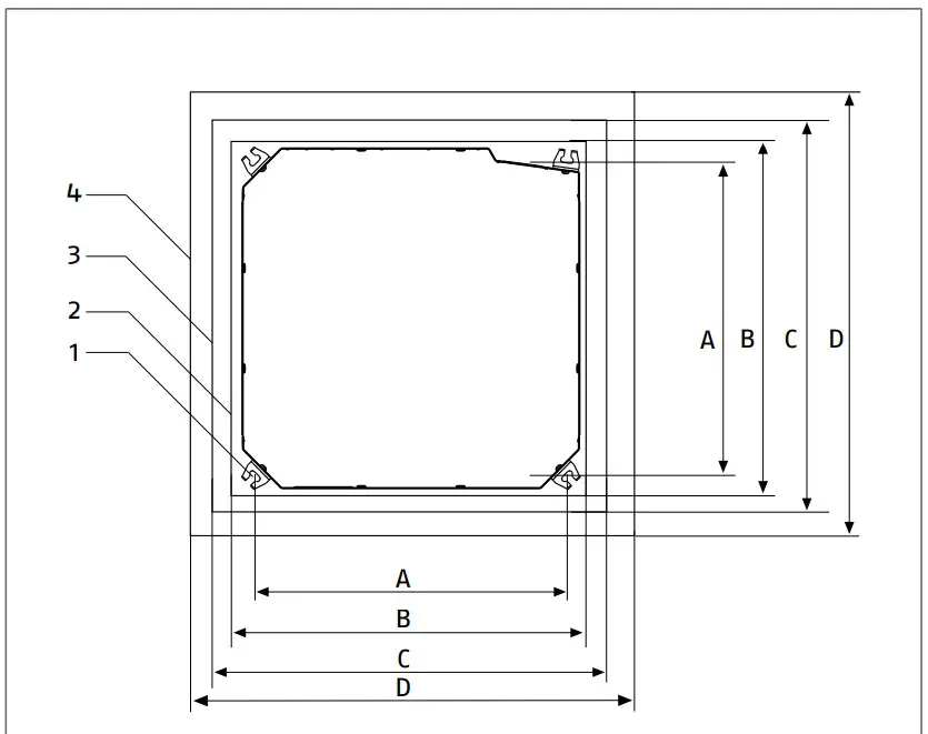
- Fastening slots
- Equipment overall dimensions
- Hole in false ceiling
- 4 ways panel overall dimensions
| Model | 100 P | 125 P | 140 P | |
| Template dimensions | ||||
| A | 765 | mm | ||
| B | 840 | mm | ||
| C | 890 | mm | ||
| D | 950 | mm | ||
Hole in false ceiling:
—— use the paper template provided for the installation
——make an opening in the false ceiling that allows insertionand links![]() The opening must be made near suitable structures to support the overall weight of the appliance and accessories.
The opening must be made near suitable structures to support the overall weight of the appliance and accessories.
Leak test:
The unit is supplied as pre-charged with nitrogen.
——partially loosen one fitting plug
——check for nitrogen leaks to verify that there is pressure inside the device![]() If pressure down, do not continue installation and check for leakage inside the unit.
If pressure down, do not continue installation and check for leakage inside the unit.![]() Contact R Technical Support Service.
Contact R Technical Support Service.
• Ceiling mounting: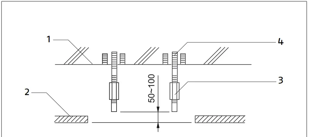
- Support wall
- false ceiling
- Fastening nut
- Threaded rods
—— use the paper template provided for the installation
——position the support rods and fix them properly to the bearing structures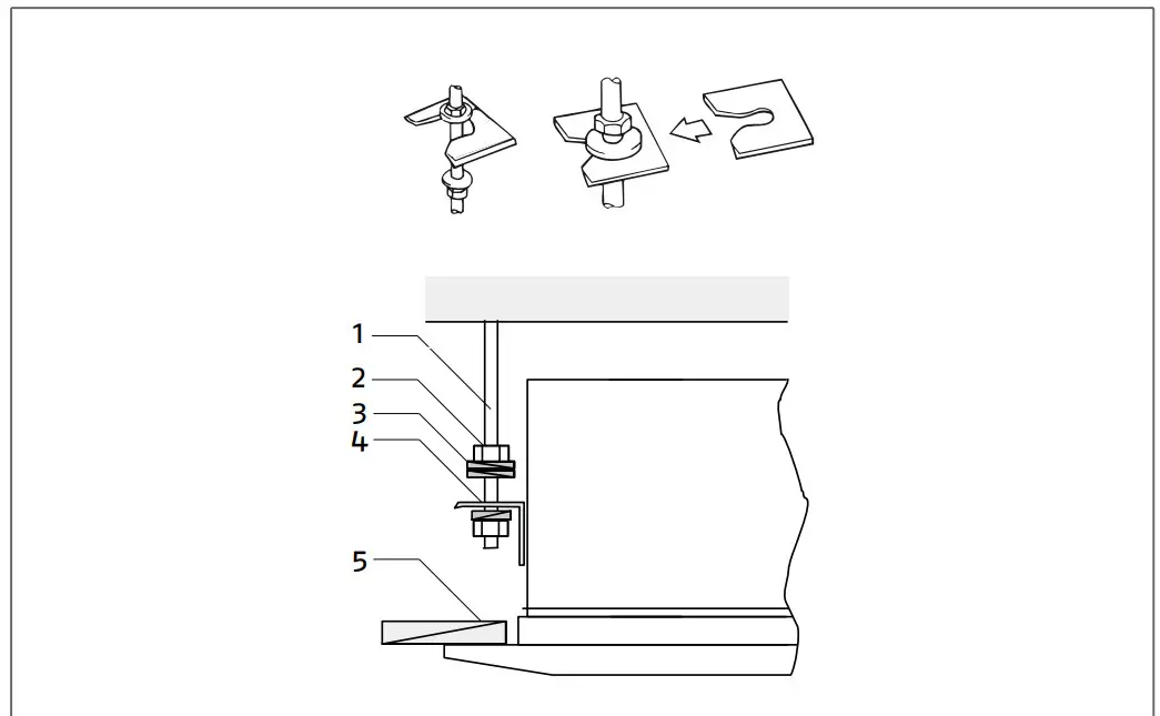
- Threaded rods
- Fastening nut
- Vibration damper
- Support bracket
- false ceiling
——place the nuts on the threaded bars
——hook the unit to the threaded bars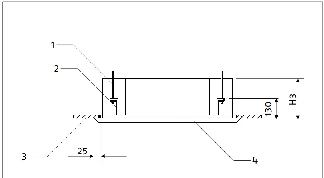
- Threaded rods
- Support bracket
- false ceiling
- 4 ways panel
| Model | 100 P | 125 P | 140 P |
| Spacing distance | |||
| H3 | 299 | 341 | mm |
——regulate the height of installation of the unit
——center the unit over the opening
——regulate the unit’s position so as to create a slope towards the condensation drainage
——tighten the fastening nut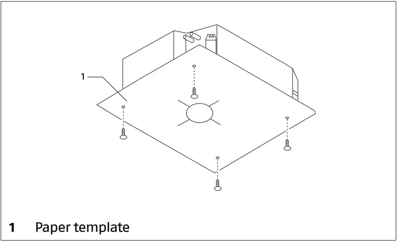
![]() If the false-ceiling is done after the installation of the device position the installation template on the unit, using the screws provided, for the reference of the dimensions of the opening to achieve.
If the false-ceiling is done after the installation of the device position the installation template on the unit, using the screws provided, for the reference of the dimensions of the opening to achieve.![]() Seal the nuts with some liquid thread lock.
Seal the nuts with some liquid thread lock.![]() The support rods must be attached to structures able to support the weight of the unit.
The support rods must be attached to structures able to support the weight of the unit.![]() The incorrect positioning of the device can cause water leakage.
The incorrect positioning of the device can cause water leakage.
Drilling into the wall:
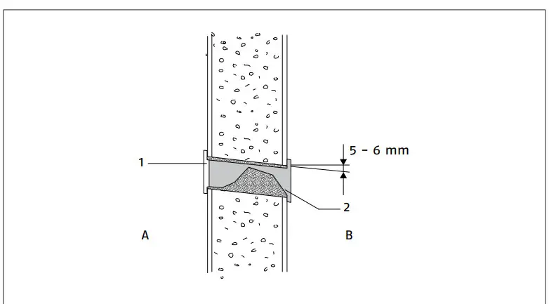 A Inner side
B Outer side
1 Hole protective insert, supplied
2 Plastic tube
——drill the through hole into the wall
——keep a downward inclination toward the external side
——insert a plastic tube in the hole in order to protect the connections
——introduce the supplied hole protection insert on the internal side of the wall
——seal with stucco![]() In case of connections on the rear side of the unit, refer to chapter “Refrigerating connection” p. 11 for the position of the hole.
In case of connections on the rear side of the unit, refer to chapter “Refrigerating connection” p. 11 for the position of the hole.
2.10 Refrigerating connection
The dimensions and positions of R AMK P cooling connections are shown hereunder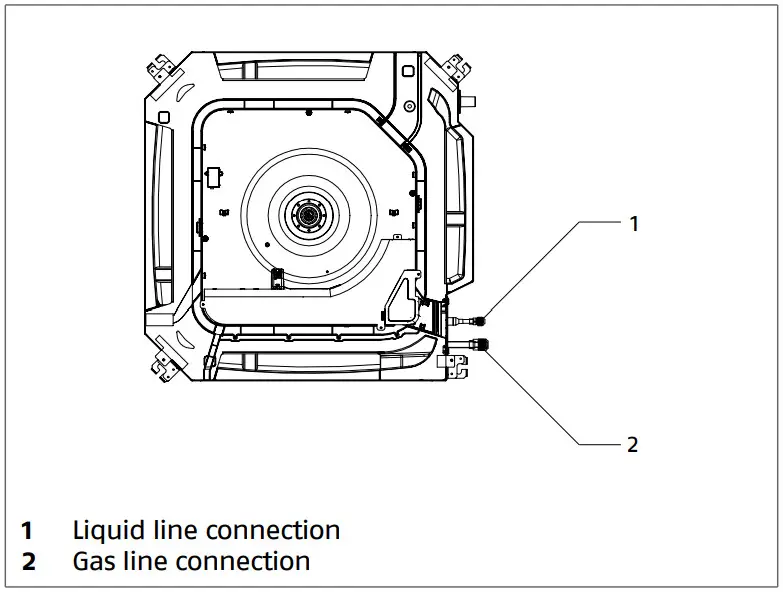
| Model | 100 P | 125 P | 140 P | |
| Connections | ||||
| Liquid line connection | 3/8 | Inches | ||
| Gas line connection | 5/8 | Inches | ||
| Liquid line connection | 9,52 | mm | ||
| Gas line connection | 15,88 | mm | ||
![]() For indications concerning distances and differences in height of connection pipes, refer to the matching outdoor unit manual.
For indications concerning distances and differences in height of connection pipes, refer to the matching outdoor unit manual.![]() Use clean hoses. Make sure the inside is free of dust, residues, water.
Use clean hoses. Make sure the inside is free of dust, residues, water.![]() Avoid the entry of uncondensable gases (air) in the circuit, otherwise, with the unit in operation, high pressures with the risk of damages might ensue.
Avoid the entry of uncondensable gases (air) in the circuit, otherwise, with the unit in operation, high pressures with the risk of damages might ensue.![]() Use copper pipes for cooling systems.
Use copper pipes for cooling systems.![]() It is forbidden to use second-hand cooling lines since their flare connection seal is not guaranteed.
It is forbidden to use second-hand cooling lines since their flare connection seal is not guaranteed.![]() It is forbidden to use pre-charged cooling lines.
It is forbidden to use pre-charged cooling lines.![]() It is forbidden to carry out welding operations with refrigerant inside the cooling circuit. If necessary, the refrigerant must be recovered and the circuit must be cleaned with nitrogen without oxygen.
It is forbidden to carry out welding operations with refrigerant inside the cooling circuit. If necessary, the refrigerant must be recovered and the circuit must be cleaned with nitrogen without oxygen.
Connections
——position the connecting pipes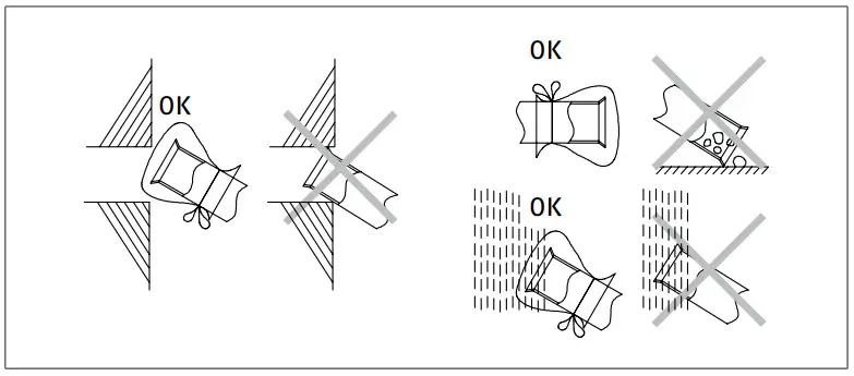
![]() Before threading the lines through the hole in the wall, close the lines ends.
Before threading the lines through the hole in the wall, close the lines ends.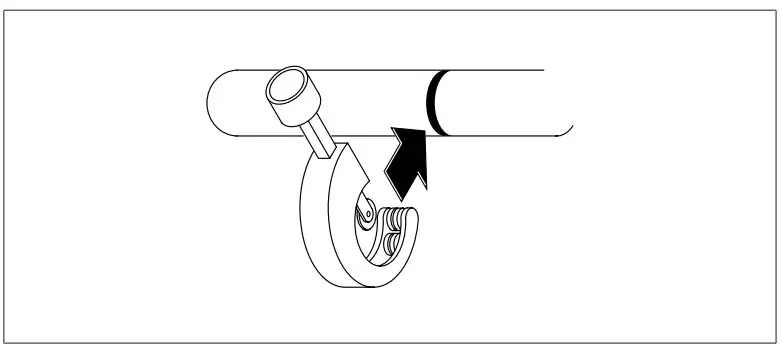 ——cut the pipe end square using a pipe cutter
——remove burrs keeping the cut edge facing down
——remove the flare nut on the unit connection
——insert it into the connection pipe
——flare the tube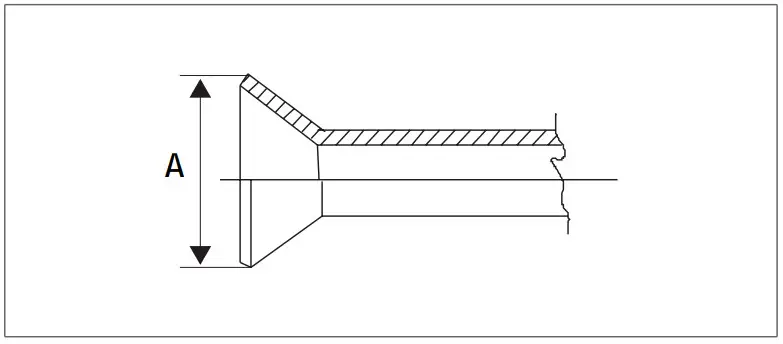
| Pipe Ø | A | |
| mm | inches | mm |
| 6,35 | 1/4 | 9,1 |
| 9,52 | 3/8 | 13,2 |
| 12,70 | 1/2 | 16,6 |
| 15,88 | 5/8 | 19,7 |
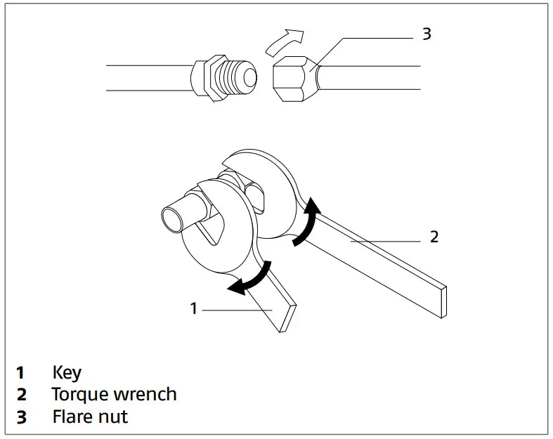
| Pipe Ø | Tightening torque | |
| mm | inches | Nm |
| 6,35 | 1/4 | 18 |
| 9,52 | 3/8 | 42 |
| 12,70 | 1/2 | 55 |
| 15,88 | 5/8 | 60 |
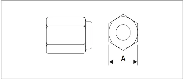
| Pipe Ø | A | |
| mm | inches | mm |
| 6,35 | 1/4 | 17 |
| 9,52 | 3/8 | 22 |
| 12,70 | 1/2 | 26 |
| 15,88 | 5/8 | 29 |
– bring line ends with flare connection close to their cou- pling on the uni
– manually rotate the flare nuts by 3 – 4 turns
– tighten the connections using a spanner and a counter spanner![]() Use a torque wrench to tighten so as to prevent damage to flare nuts and gas leaks.
Use a torque wrench to tighten so as to prevent damage to flare nuts and gas leaks.![]() Use equipment suitable for the system refrigerant.
Use equipment suitable for the system refrigerant.![]() Avoid using the refrigerant oil on the external part of the flaring.
Avoid using the refrigerant oil on the external part of the flaring.![]() Avoid proximity to sources of ignition in continuous op- eration (open flames, gas household appliances, electric stoves, etc.).
Avoid proximity to sources of ignition in continuous op- eration (open flames, gas household appliances, electric stoves, etc.).
As for circuit leak and pneumatic vacuum tests, refer to the matching outdoor unit instruction booklet for the installer.
Pipe insulation
Connection pipes must be thermally insulated to prevent dis- persions of heat or formation of condensate.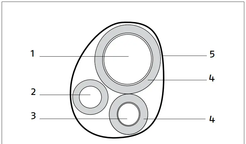
- Gas pipe
- Condensation discharge
- Liquid pipe
- Heat insulation
- Adhesive tape
— insulate the liquid and gas pipes separately
– use insulating material that is thicker than 15 mm
– ensure that the insulating material adheres to the pipe without gaps
– fix using adhesive tape
Do not tighten the adhesive tape too much, so as to avoid damaging the insulation.
Avoid partial insulation of the pipes.
In case of use with outdoor temperature above 30 °C and relative humidity above 80%, increase wall thickness up to 20 mm.
For gas pipes:
- ensure that the material used resists to temperatures up to 120°C
For liquid pipes:
- ensure that the material used resists to temperatures up to 70°C
2.1 Condensate discharge connection
R AMK P is equipped with condensate drain pan which is produced during cooling operation and which must be con- veyed to a place suitable for drain
The unit is equipped with a drain pump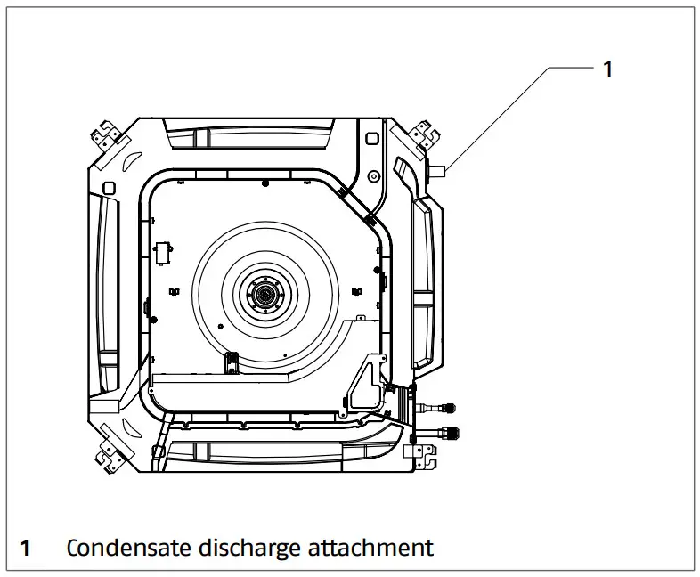
| Model | 100 P | 125 P | 140 P | |
| Connections | ||||
| Condensate discharge attachment Ø | 26 / 32 | 25 | mm | |
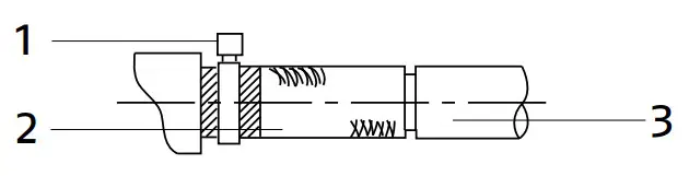
- Hose clamp
- Condensate discharge pipe
- Drainage pipe
– connect a rubber drainage pipe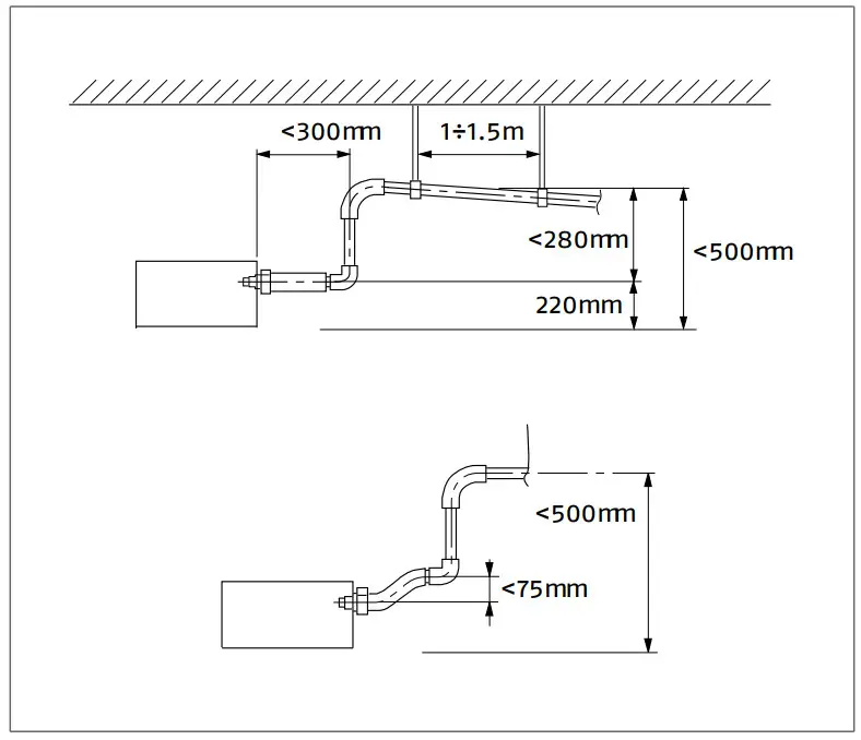
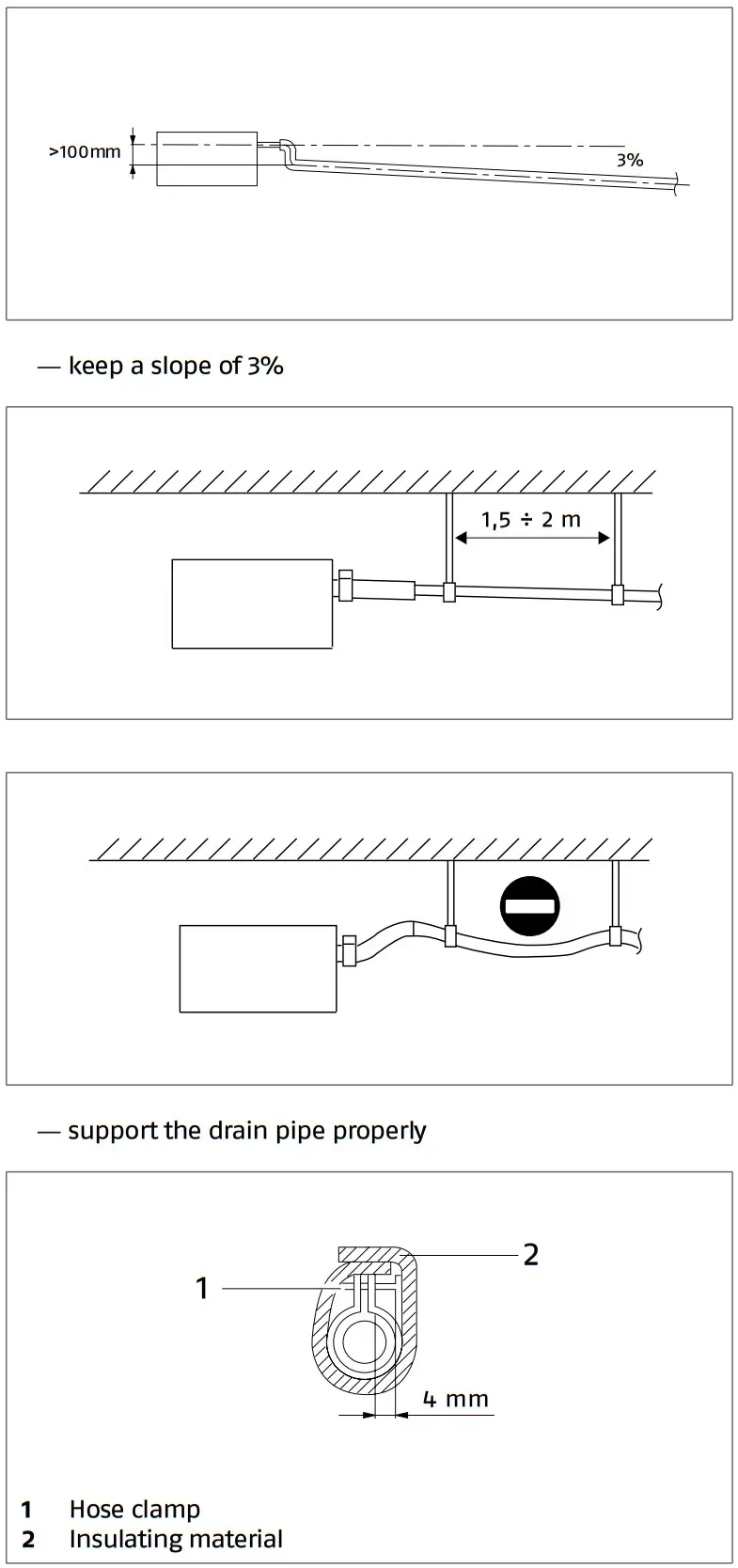
insulate the joints
The discharge system must feature a suitable syphon in or- der to prevent air from entering the vacuum system. The sy- phon also prevents odours and insects from entering the system.
The syphon must feature a plug in its lower part or must otherwise allow for a quick disassembly for cleaning pur- poses.
Ensure that all joints are properly sealed so as to prevent water leaks.![]() The drainage pipe must be insulated for sections running inside houses in order to prevent condensate formation on its surface.
The drainage pipe must be insulated for sections running inside houses in order to prevent condensate formation on its surface.
Drainage check:
- After electrical connection:
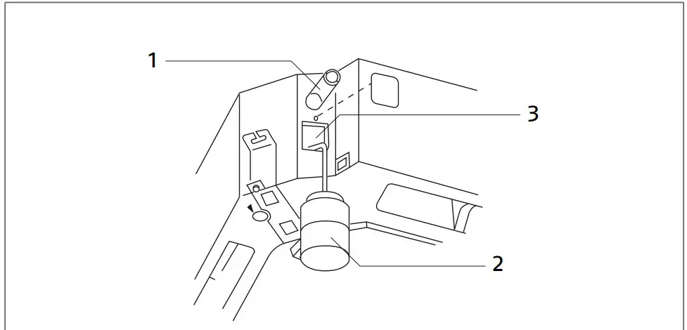
- Condensate discharge attachment
- Plastic bottle with pump
- Inspection hole
- charge 1,2 liters of water trough the inspection hole
- turn on the unit in cooling mode
- check that it flows out correctly through the drainage pipe
External air intake
External air intake
If required it is possible to take external fresh air through the connection provided on the unit and the installation of a mo- torized damper to regulate the flow rate.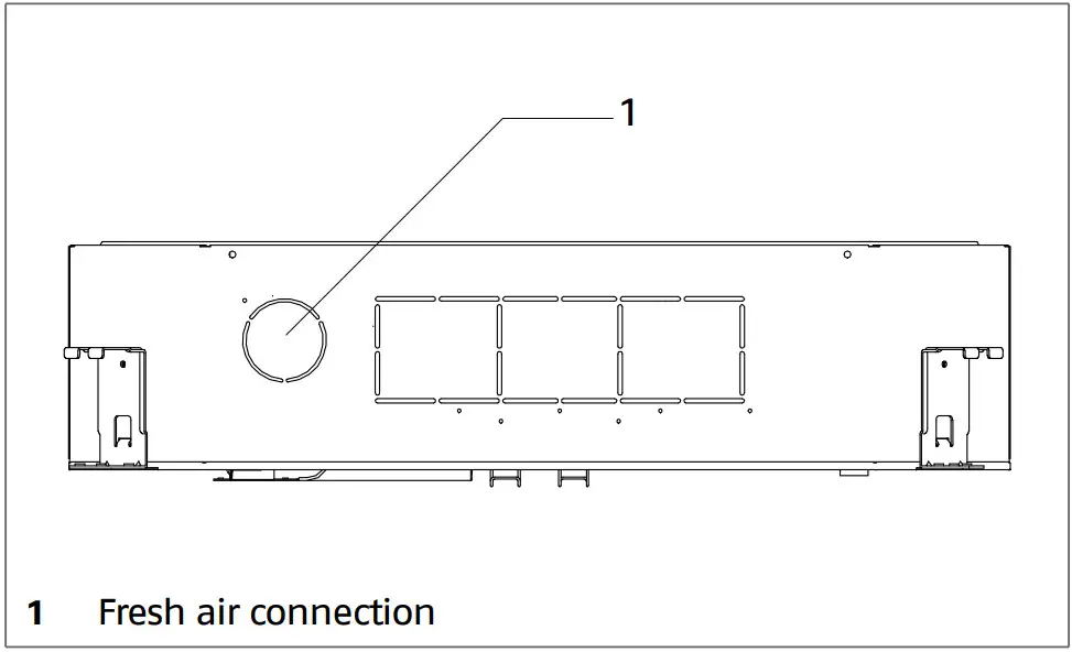
- connect a circular duct to the prepared connection
- connect the damper motor to the connector provided on the electronic board
- check chapter “Wiring diagram” 15
- set microswitch SW01-6 = OFF
- check chapter “Microswitch setting” 22
2.12 Wiring diagram
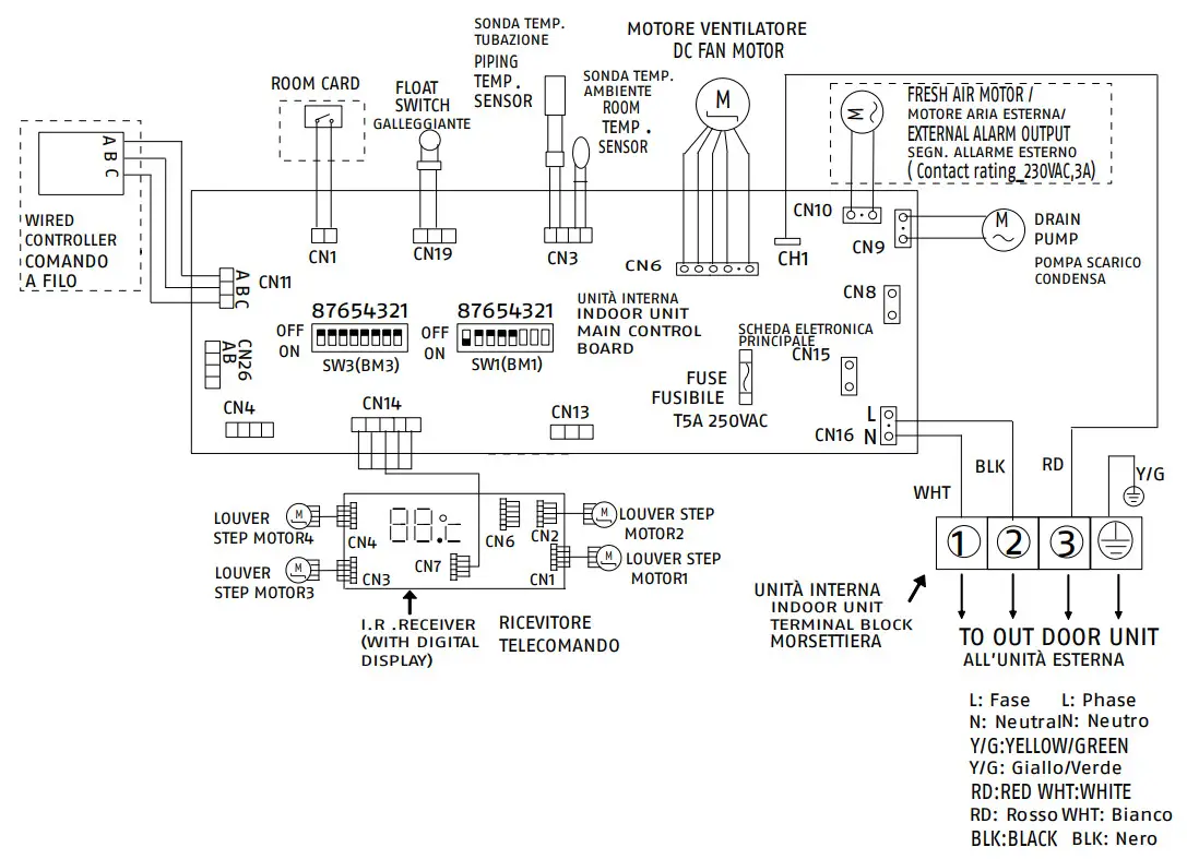
![]() The dotted parts are optional.
The dotted parts are optional.![]() Contact CN13, is bridged by factory default.
Contact CN13, is bridged by factory default.![]() Do not change SW01 and SW03 Dip Switch position without reading the instruction inside the paragraph “Microswitch setting” p. 22.
Do not change SW01 and SW03 Dip Switch position without reading the instruction inside the paragraph “Microswitch setting” p. 22.![]() E.A.O. = external alarm output select SW01-6 = ON to engage. When SW01-6 select OFF means FRESH AIR function engaged (CN9 is a 230VAC wet contact output).
E.A.O. = external alarm output select SW01-6 = ON to engage. When SW01-6 select OFF means FRESH AIR function engaged (CN9 is a 230VAC wet contact output).![]() SW03-5 ->SW03-8 are used to address more indoor units to one wired control panel. For information read the paragraph “Microswitch setting” p. 22.
SW03-5 ->SW03-8 are used to address more indoor units to one wired control panel. For information read the paragraph “Microswitch setting” p. 22.
2.13 Electrical connection
AMK P it leaves the factory completely wired, and only requires a connection to the outdoor unit.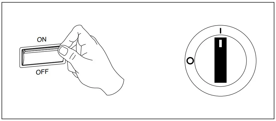
— —position the system’s main switch in the “OFF” position.
To access the terminal board: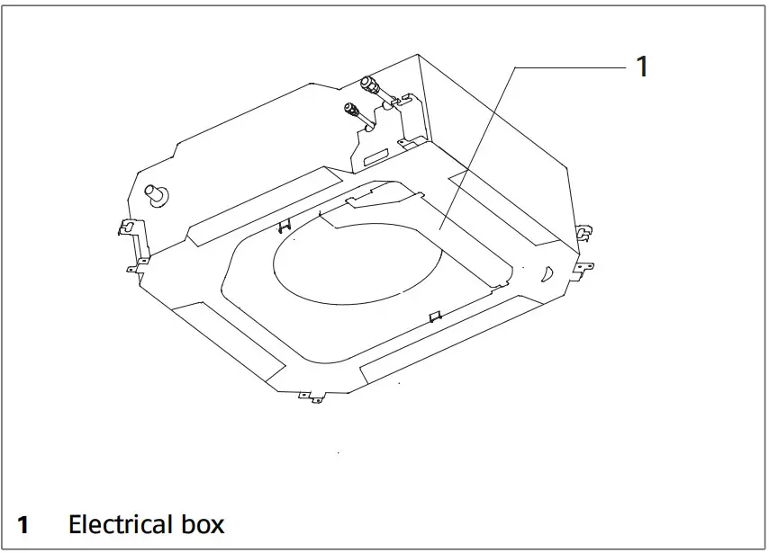
——unscrew the fastening screw
——remove the electric panel access panel![]() If already assembly, remove the 4-way panel following the instructions in the chapter “4 ways panel” p. 16.
If already assembly, remove the 4-way panel following the instructions in the chapter “4 ways panel” p. 16.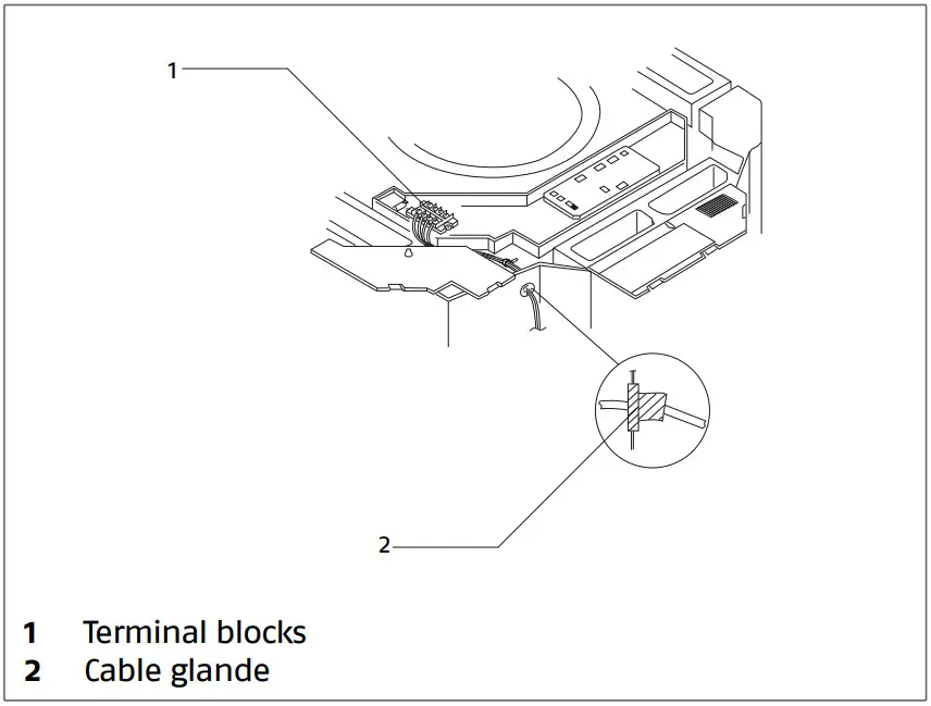 —make the electric connections according to the diagrams on the installation booklet of the matching outdoor unit
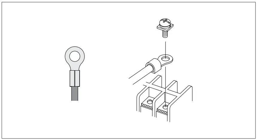
![]() It is compulsory to use ring crimp terminals to connect to the terminal board.
It is compulsory to use ring crimp terminals to connect to the terminal board.
For the sizing of the electrical cables, use the following table:
| Model | 100 P | 125 P | 140 P | |
| Electrical characteristics | ||||
| Power supply | 230/1/50 | V/Ph/Hz | ||
| Protection factor | 24 | IP | ||
| Power cable Signal cable | 3 x 4 | 5 x 4 | n. x mm² | |
| 4 x 2,5 | n. x mm² | |||
The cable sections specified in the table are minimum requirements. The correct size must be calculated taking into account the actual length, the type of routing and other conditions set by the existing regulations.
——fasten the wires with the wire retainer
——check the correct positioning of the cable gland
——complete the electric connections and refit all components by performing the described operations in reverse order
Mandatory items:
——connect the device to a properly functioning earthing system
——for any electrical intervention, always refer to the wiring diagrams contained within this booklet
——take anti-static precautions in case of weather conditions where humidity is less than 40%
Electric connections shall be made in compliance with national regulations.![]() Avoid placing the connection cables less than 1 metre away from radio and video systems.
Avoid placing the connection cables less than 1 metre away from radio and video systems.![]() Avoid using mobile phones.
Avoid using mobile phones.![]() It is forbidden to earth the device together with pipes, lightning conductors or the earthing system of a telephone line. Using an improper earthing system can cause electric shocks.
It is forbidden to earth the device together with pipes, lightning conductors or the earthing system of a telephone line. Using an improper earthing system can cause electric shocks.
4 ways panel
After all electrical connections, proceed with the assembly of the 4-way panel.
Air intake grille removal: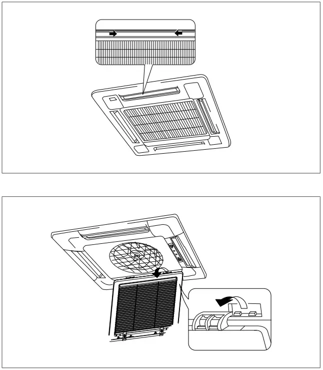
——open the grill
——keep a angle of 45°
——unfasten grill
——remove grill
Corner insert removal: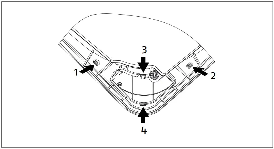
——press gently on the fixing inserts
——follow the order shown in the figure
——remove the corner insert
——perform the operation for all the corner inserts
Panel frame assembly: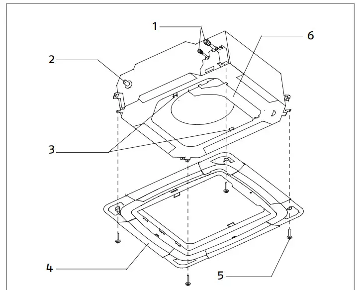
- Refrigerant connections
- Condensation discharge
- Panel hooks
- Panel frame
- Fixing screws
- Electrical box
——open the panel hooks
——place the frame
——close the panel hooks
—— use the screws provided
——fasten the frame to the unit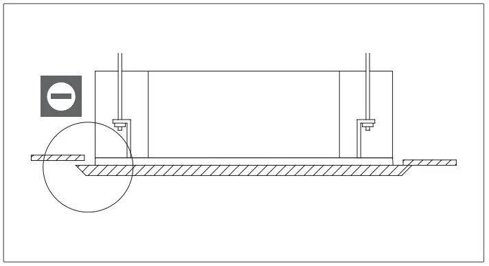
![]() It is forbidden to leave spaces between the frame and the false ceiling.
It is forbidden to leave spaces between the frame and the false ceiling.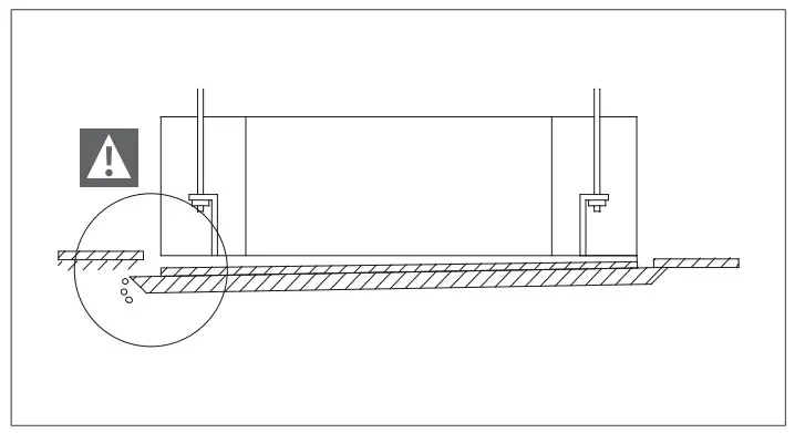
——check that the frame adheres perfectly to the false ceiling![]() The incorrect positioning of the frame can cause water leakage.
The incorrect positioning of the frame can cause water leakage.
If required: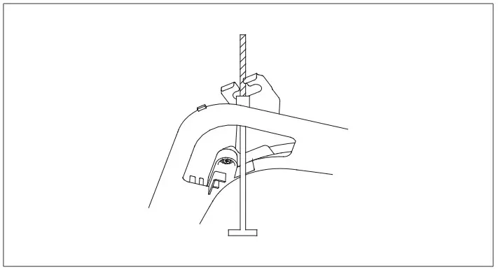 ——work on unit fixings
——regulate the height of installation of the unit
Electric connections: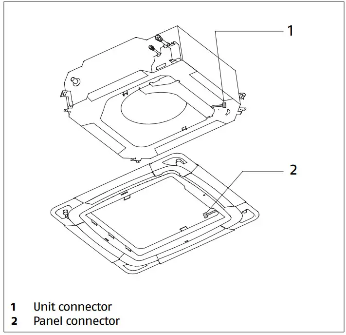 ——link the frame connectors to the unit
Corner inserts assembly: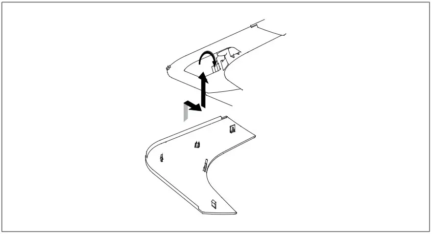 ——hook the corner inserts to the frame
Intake grid assembly:
——fit the grill
——reverse the procedure
After assembly, it may be necessary to remove the 4-way panel.
Corner insert removal: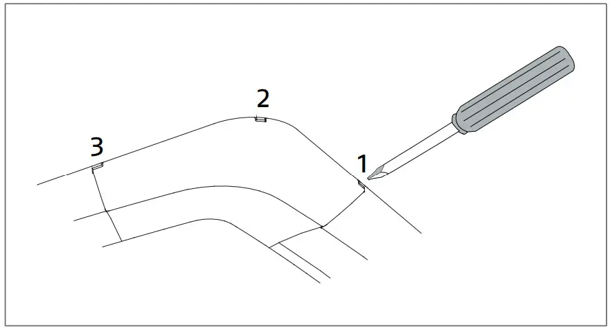
——Use a screwdriver
——press gently on the fixing inserts
——remove the corner insert
——perform the operation for all the corner inserts
4 ways panel removal:
——reverse the procedure
2.14 Remote control
Control, setting and programming operations are carried out with the IR remote control.
The electronics modulates the device operation according to the temperatures detected by the probes inside the indoor and outdoor units.
Battery insertion
The remote control is powered by two AAA batteries (1.5 V) housed at the back, under a cover.
Should you notice a poorer reception or if display information fades out, the batteries must be changed.
To fit or change batteries: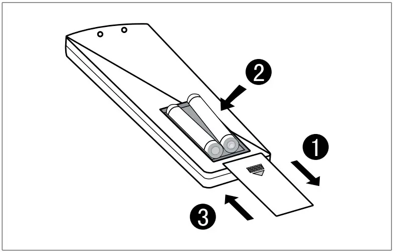 ——remove the cover by pressing it down and lifting it up
——if present, remove old batteries
——fit new batteries according to proper polarity
![]() Two 1.5V AAA batteries are supplied with the unit for its first set-up.
Two 1.5V AAA batteries are supplied with the unit for its first set-up.![]() Never mix and match new and old batteries or different types of batteries.
Never mix and match new and old batteries or different types of batteries.![]() When you remove the batteries, all settings in the remote control will be deleted. Fit the new batteries and reprogram.
When you remove the batteries, all settings in the remote control will be deleted. Fit the new batteries and reprogram.![]() Do not dispose of old batteries in the environment. Always take them to the suitable containers at points of sale.
Do not dispose of old batteries in the environment. Always take them to the suitable containers at points of sale.
Function keys
The remote control features a small door in the key area:
DOOR CLOSED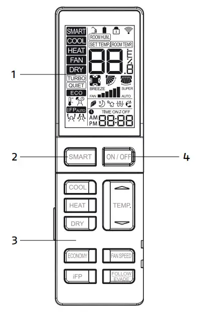
- Display
- Smart button
- Quick function keys
- On- Off key
When the door is closed, you can activate the quick functions, such as choosing the operating mode and setting the desired temperature.
Ensure that the door is fully closed. If this is not the case, the external keys will not work.
Function keys with door closed
| Enables Automatic mode | |
| It switches the device on and off | |
| It activates the Cooling mode | |
| It activates the Heating mode | |
| It activates the Dehumidification mode | |
| It increases or decreases the selected parameter value | |
| Enables ECO function | |
| Function not available | |
| Select required ventilation speed: minimum, medium, maximum or automatic | |
| Function not available |
DOOR OPEN
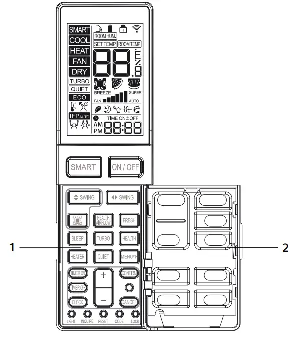
- Door
- Advanced function keys
When the door is open, you can access the advanced functions, e.g. time scheduling and motor-driven deflector settings.
Function keys with door open
| It activates and deactivates the automatic movement of the horizontal deflector or stops it in a specific position | |
| It activates and deactivates the automatic movement of the vertical deflector or stops it in a specific position “Function not available for Cassette unit | |
| Select the desired deflector | |
| It enables the Health Air Flow function | |
| Enable Fresh function (low speed ventilation) Not available for Consolle unit | |
| It activates the Sleep function | |
| Enable Turbo function (maximum speed ventilation) | |
| Function not available | |
| Function not available | |
| Enable Quiet function | |
| It switches the temperature scale from Celsius to Fahrenheit and vice versa | |
| Gives access to Timer ON settings | |
| Gives access to Timer OFF settings | |
| It gives access to current time change settings | |
| It increases or decreases the selected parameter value | |
| Confirm the settings | |
| Delete the settings | |
| Switch on or off the unit display | |
| Indoor unit processing | |
| Press to restart the air conditioner | |
| Private function | |
| Keys locking |
Remote control display
The remote control display shows the settings as changed by the user and the detected weather conditions.
The backlit display is divided in areas according to function type.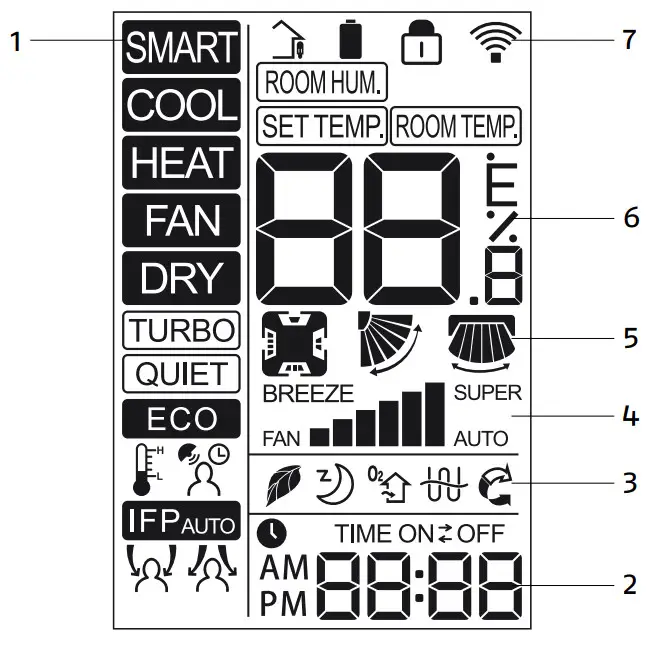
- Operating mode
- Timer settings
- Functions
- Fan settings
- Motor-driven deflector settings
- Climatic settings
- Remote control status
Operating mode
| Smart mode enabled | |
| Cooling mode enabled | |
| Heating mode enabled | |
| Ventilation mode enabled | |
| Dehumidification mode enabled | |
| Turbo function enabled | |
| Quiet function enabled | |
| Economy function enabled | |
| Not available |
Timer settings
| Timer setting value or current time display | |
| Switch on timer enabled | |
| Switch off timer enabled |
Functions
| Not available | |
| Sleep function enabled | |
| Fresh function enabled Not available for Consolle unit | |
| Not available | |
| Health Airflow function enabled |
Fan settings
| Fan speed set | |
| Quiet speed enabled | |
| Turbo speed enabled | |
| Auto speed enabled |
Motor-driven deflector settings
| Deflectors enabled Available for Cassette unit only | |
| Horizontal deflector position | |
| Vertical deflector position Not available for Cassette unit |
Climatic settings
| 1. Detected ambient humidity | |
| 2. Required temperature when using the button | |
| 3. Detected ambient temperature |
Remote control status
| Signal transmission upon pressing the keys | |
| Battery level | |
| Remote control keys locked | |
| WiFi connection enabled |
Unit display
The unit display shows the active functioning mode, the temperature and the alarms, if any.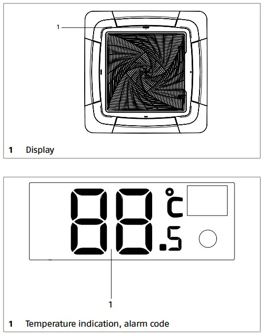
COMMISSIONING AND MAINTENANCE
3.1 Preparation for first commissioning
Prior to commissioning, it is necessary to check that:
——all the safety conditions have been met
——all distances have been respected
——the electrical connections have been properly completed
——power supply values are correct.
——the earthing has been carried out correctly
——all the connections have been properly tightened
Microswitch setting
On the main electronic board there are microswitches to manage some functions.
Factory settings
| Model | SW01 | |||||||
| 1 | 2 | 3 | 4 | 5 | 6 | 7 | 8 | |
| 100 P | ON | OFF | ON | OFF | OFF | OFF | OFF | ON |
| 125 P | OFF | ON | ON | OFF | OFF | OFF | OFF | ON |
| 140 P | ON | ON | ON | OFF | OFF | OFF | OFF | ON |
SW01-1, SW01-2, SW01-3
Model setting; do not change.
SW01-4
It enables and disables the “Roomcard” function: OFF = disabled (factory setting)
——if the clean contact “Roomcard” opens, the unit will turn off automatically. Remote control can be used to turn on the unit again
——if the clean contact “Roomcard” closes, the unit will prepare to start in stand-by mode. Remote control must be used to turn on the unit again ON = enabled
——if the clean contact “Roomcard” opens, the unit will turn off automatically. Remote control can not be used to turn on the unit again
——if the clean contact “Roomcard” closes, the unit will prepare to start in stand-by mode. Remote control must be used to turn on the unit again![]() Contact “Roomcard” is bridged by factory default.
Contact “Roomcard” is bridged by factory default.![]() For the location of the free contact and its connector, refer to the chapter “Wiring diagram” p. 15.
For the location of the free contact and its connector, refer to the chapter “Wiring diagram” p. 15.
SW01-5
Heat pump operation (OFF) or only cooling operation (ON).![]() Factory set is heat pump (OFF).
Factory set is heat pump (OFF).
SW01-6, SW01-7, SW01-8
Model setting; do not change.![]() Cut off the power supply before adjusting.
Cut off the power supply before adjusting.
| Model | SW03 | |||||||
| 1 | 2 | 3 | 4 | 5 | 6 | 7 | 8 | |
| 100 P | OFF | OFF | OFF | OFF | OFF | OFF | OFF | OFF |
| 125 P | OFF | OFF | OFF | OFF | OFF | OFF | OFF | OFF |
| 140 P | OFF | OFF | OFF | OFF | OFF | OFF | OFF | OFF |
SW03-1, SW03-2, SW03-3, SW03-4
Reserved. Do not change factory setting
SW03-5, SW03-6, SW03-7, SW03-8
Reserved switches for addressing multiple indoor units to a single control panel. For instructions, refer to the user manual of the wired control panel.![]() The indoor unit is factory-set as a master unit (OFF).
The indoor unit is factory-set as a master unit (OFF).
Time setting
The current time must be set before using the remote control: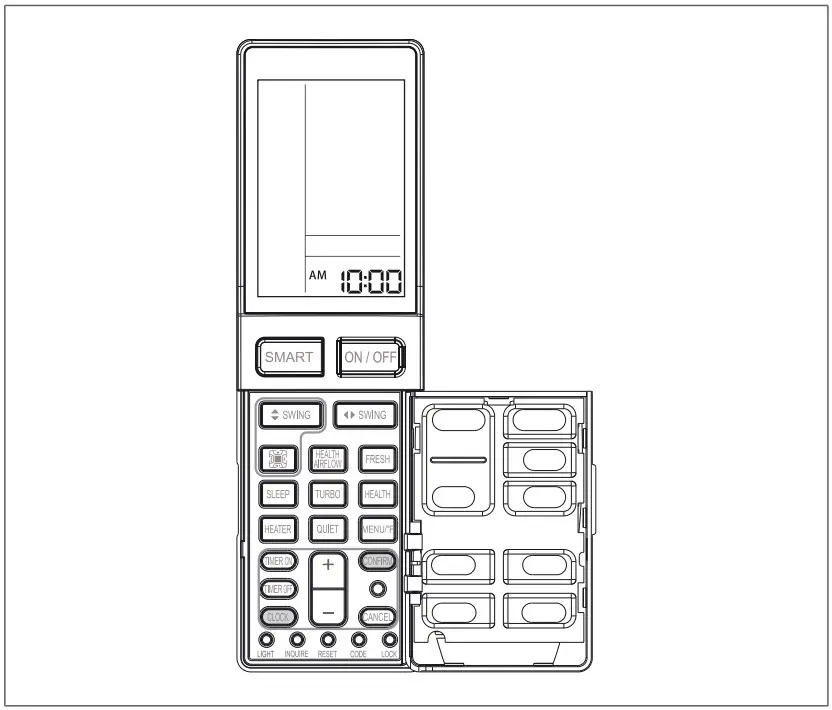
——open the door
——press![]()
— —work on![]()
— —select the current time
Each time the key is pressed, the values changes by 1. By keeping the key pressed down, the value changes faster.
——confirm with![]()
3.2 Putting into service
After having completed all the operations required to prepare for first commissioning, do the following to activate the device: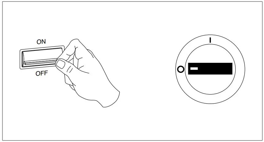 — —position the system’s main switch in the “ON” position.
——activate the unit with the remote control
——check its operation in the different modes![]() The compressor activates 3 minutes after unit activation.
The compressor activates 3 minutes after unit activation.
![]() Refer to the user booklet as for the use of the remote control.
Refer to the user booklet as for the use of the remote control.
Start-up in cooling mode with low temperatures
When the indoor air temperature is less than 16 °C the unit does not start in cooling mode. In case either it is necessary to check the operation in these conditions it can be used the emergency switch positioned on the unit’s electronic board.
Open the electrical panel and access the electronic board following what is indicated in the chapter “Electrical connec- tion” p. 16.
To switch on:
——keep the emergency switch pressed down until a double acoustic signal is emitted
——the air-conditioner starts in cooling mode with high ventilation speed and active air deflector
To switch off:
——press the emergency switch again![]() This operation must be carried out in specific conditions and not for usual operation.
This operation must be carried out in specific conditions and not for usual operation.
Checks during and after the first commissioning
Monthly operations
After starting the device, check that:
——the current consumed by the compressor is less than the maximum permitted
——the device is operating under the recommended operating conditions
——the unit is able to stop and start up again![]() Should any of the above-listed controls have problems: turn the device off and call the Technical Service immediately.
Should any of the above-listed controls have problems: turn the device off and call the Technical Service immediately.![]() Do not touch the device pipes to prevent potential burns.
Do not touch the device pipes to prevent potential burns.![]() Take anti-static precautions in case of weather conditions where humidity is less than 40%.
Take anti-static precautions in case of weather conditions where humidity is less than 40%.![]() Avoid using mobile phones.
Avoid using mobile phones.
3.3 Temporary shutdown
In order to shut down the unit for periods of brief absences:
——only use the remote control to disable the unit
3.4 Stop for an extended period of time
If the device has not been used for an extended period of time, carry out the following operations:
——start the device in ventilation mode
——select the maximum speed
——let the device run for 6 hours
——deactivate the unit with the remote control
— —position the system’s main switch in the “OFF” position.
3.5 Ordinary maintenance
Routine maintenance is fundamental for keeping the equipment efficient, safe and reliable. It can be performed periodi- cally by the Technical Support Service, whose staff is technically qualified and can use genuine spare parts, if necessary.![]() Original conditions must be restored after performing the required maintenance operations.
Original conditions must be restored after performing the required maintenance operations.![]() All described operations MUST be carried out under the following conditions:
All described operations MUST be carried out under the following conditions:
——cold device
——device NOT supplied with electric power
——suitable personal protection equipment![]() Do not open the access covers and carry out technical or cleaning activities before disconnecting the unit from the power grid by positioning the system’s main switch in the “OFF” position
Do not open the access covers and carry out technical or cleaning activities before disconnecting the unit from the power grid by positioning the system’s main switch in the “OFF” position
Monthly operations
The following checks are part of the monthly maintenance plan:
——cleaning the housing and front panel
——mesh filter cleaning
Cleaning 4 ways panel
——wet a sponge or soft cloth with water and soap to wash
——once cleaning is over dry surfaces with care![]() Do not use water at a temperature that is higher than 40°C, powder or abrasive detergents, solvents and brushes.
Do not use water at a temperature that is higher than 40°C, powder or abrasive detergents, solvents and brushes.
Mesh filter cleaning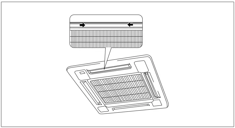
——open the air intake grill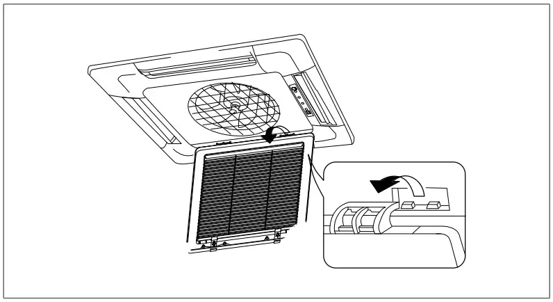 ——unfasten grill
——remove grill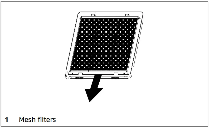
——take out the mesh filter by grabbing the relevant fins
——remove dust with an vacuum cleaner![]() Stubborn dirt can be removed by washing the filter in a luke warm (max. 40 °C) solution of water and neutral detergent.
Stubborn dirt can be removed by washing the filter in a luke warm (max. 40 °C) solution of water and neutral detergent.
After washing, rinse the filters well and leave to dry in the shade.![]() Exposing the filters to the sun or washing them with water at a temperature that is higher than 40 °C can cause the filters to shrink.
Exposing the filters to the sun or washing them with water at a temperature that is higher than 40 °C can cause the filters to shrink.![]() It is forbidden to use the device without mesh filter.
It is forbidden to use the device without mesh filter.
Yearly operations
The annual maintenance plan includes the following checks:
——power supply voltage
——electric connection tightening
——status of cooling and hydraulic joint
——condensate tray cleaning
——electric absorption
3.6 Extraordinary maintenance
Removal
In case of replacement or extraordinary reparations, you may need to remove the unit.
Proceed as follows to remove the capacitors:
——carry out the evaporator emptying operation![]() The operation is detailed in the Installer booklet of the matching outdoor unit.
The operation is detailed in the Installer booklet of the matching outdoor unit.
——deactivate the unit with the remote control
——position the system’s main switch in the “OFF” position.
——disconnect the cooling pipes
——disconnect the condensate discharge
——disconnect the electric connections
——loosen the fastening nuts
——unfasten the unit from the threaded bars
——remove the unit
3.7 Alarms
In the presence of operating abnormalities, the unit is secured and blocked.![]() Safety block can occur randomly.
Safety block can occur randomly.![]() Wait for at least 10 minutes before restarting the unit.
Wait for at least 10 minutes before restarting the unit.![]() If the fault occurs again, an accurate check of the device components is required. Contact R Technical Support Service.
If the fault occurs again, an accurate check of the device components is required. Contact R Technical Support Service.
Faults are identified by a code on the control display and by LED 1 blinking on main board.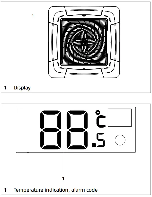 Indoor unit faults
| LED1 | Display | Description | Remarks |
| 1 | 01 | Room probe fault |
The unit resets after problem resolution |
| 2 | 02 | Exchanger probe fault | |
| 4 | 04 | Microprocessor malfunction | |
| 7 | 07 | Communication error between indoor unit and outdoor unit | |
| 8 | 08 | Communication error between unit and control panel | |
| 12 | 0C | Malfunction condensation drain system | |
| 13 | 0D | Zero cross signal detected wrong | |
| 14 | 0E | Fan motor malfunction |
Outdoor unit faults
![]() Refer to the matching outdoor unit instruction booklet for the installer.
Refer to the matching outdoor unit instruction booklet for the installer.
DISPOSAL
Packaging materials shall be disposed of separately so as to recover and recycle them. At the end of its service life, the device shall be disposed of according to the existing legislation.
![]() RIELLO S.p.A. – 37045 Legnago (VR)
RIELLO S.p.A. – 37045 Legnago (VR)
tel. +39 0442 630111 – fax +39 0442 630371
www.riello.it
As the manufacturer is constantly improving its products, the aesthetic or dimensional features,
the technical data, the equipment and accessories indicated could be subject to variations.


