![]()
Endeavor™ Line Classic Plus® Series
iM Air Conditioners
 RA15AZ
Cooling Efficiency: 15.2 SEER2/9.8 EER2
Nominal Sizes: 2 to 5 Ton [7.0 to 17.6 kW]
Cooling Capacities: 22.8 to 56.0 kBTU [6.68 to 16.4 kW]


Features and Benefits
- EcoNet®
Enabled: Automatic system configuration and optimization - PlusOne® Diagnostics & Bluetooth Connectivity: With the Rheem Contractor & EcoNet® Apps, built-in technology makes advanced set-up, monitoring, troubleshooting and repairing the product easier than ever before.
- PlusOne®
Variable Speed Twin Rotary Compressor & Inverter Drive:
—Features Inverter operation from 40 to 70% capacity or 100% capacity via line voltage with the EcoNet® Smart Thermostat
— 3-speed operation when installed with a 24V two-stage
— Provides precise temperature control, advanced humidity control and greater efficiency - Swept Wing Fan Technology: Features quieter operation and improved unit acoustics
- 7mm Condenser Copper Coil: Requires less refrigerant allowing for a smaller and lighter footprint while enhancing reliability
- PlusOne® Expanded Value Space: 3 in. – 4 in. – 5 in. service valve space—provides a minimum working area of 27-square inches for easier access
- PlusOne® Triple Service Access: 15 in. wide, industry leading corner service access, two fastener, removeable corner and individual louver panels–makes repairs easier and faster
Model Number Identification
RA15AZ
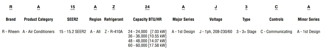
[ ] Designates Metric Conversions
| AVAILABLE MODELS | DESCRIPTION |
| RA15AZ24AJ3CA | Endeavor™ Line Classic Plus® Series 2 ton EcoNet® Enabled 3+ Speed iM Air Conditioner – 208/230/1/60 |
| RA15AZ36AJ3CA | Endeavor™ Line Classic Plus® Series 3 ton EcoNet® Enabled 3+ Speed iM Air Conditioner – 208/230/1/60 |
| RA15AZ48AJ3CA | Endeavor™ Line Classic Plus® Series 4 ton EcoNet® Enabled 3+ Speed iM Air Conditioner – 208/230/1/60 |
| RA15AZ60AJ3CA | Endeavor™ Line Classic Plus® Series 5 ton EcoNet® Enabled 3+ Speed iM Air Conditioner – 208/230/1/60 |
| STANDARD EQUIPMENT |
| R-410A Refrigerant |
| Maximum SEER2: 15.2 SEER2 |
| Maximum EER2: 9.8 EER2 |
| Variable Speed Twin Rotary Compressor |
| Field Installed Filter Drier |
| Front Seating Service Valves |
| Internal Pressure Relief Valve |
| Internal Thermal Overload |
| Long Line capability |
| Low Ambient capability with Kit |
| 3-4-5 Expanded Valve Space |
| Composite Basepan |
| 2 Screw Control Box Access |
| 15″ Access to Internal Components |
| Quick release louver panel design |
| No fasteners to remove along bottom |
| Optimized Venturi Airflow |
| Single row condenser coil |
| Powder coated paint |
| Rust resistant screws |
| QR code |
| External gauge ports |
| Service trays |
General Data/Electrical Data
| General Data | ||||
| MODEL NO. | RA15AZ24AJ3 | RA15AZ36AJ3 | RA15AZ48AJ3 | RA15AZ60AJ3 |
| Nominal Tonnage | 2.0 | 3.0 | 4.0 | 5.0 |
| Valve Connections | ||||
| Liquid Line O.D. – in. | 3/8 | 3/8 | 3/8 | 3/8 |
| Suction Line O.D. – in. | 3/4 | 3/4 | 7/8 | 7/8 |
| Refrigerant (R410A) furnished oz.¹ | 91 | 119 | 130 | 154 |
| Compressor Type | Twin Rotary | |||
| Outdoor Coil | ||||
| Net face area – Outer Coil | 11.79 | 14.4 | 16.42 | 17.88 |
| Net face area – Inner Coil | — | — | — | — |
| Tube diameter – in. | 0.276 | 0.276 | 0.276 | 0.276 |
| Number of rows | 1 | 1 | 1 | 1 |
| Fins per inch | 24 | 24 | 24 | 24 |
| Outdoor Fan | ||||
| Diameter – in. | 20 | 24 | 24 | 26 |
| Number of blades | 3 | 3 | 3 | 3 |
| Motor hp | 1/4 | 1/5 | 1/2 | 1/2 |
| CFM | 2904 | 4138 | 4422 | 5234 |
| RPM | 1075 | 1000 | 1075 | 1075 |
| watts | 297 | 267 | 401 | 463 |
| Shipping weight – lbs. | 157 | 158 | 200 | 215 |
| Operating weight – lbs. | 149 | 150 | 192 | 207 |
| Electrical Data | ||||
| Line Voltage Data (Volts-Phase-Hz) | 208/230-1-60 | 208/230-1-60 | 208/230-1-60 | 208/230-1-60 |
| Maximum overcurrent protection (amps)² | 20 | 30 | 40 | 0 |
| Minimum circuit ampacity5 | 12 | 20 | 25 | 0 |
| Compressor | ||||
| Rated load amps | 10 | 15 | 20 | 0 |
| Locked rotor amps | 65 | 70 | 96 | 119 |
Accessories
| MODEL NO. | RA15AZ24AJ3 | RA15AZ36AJ3 | RA15AZ48AJ3 | RA15AZ60AJ3 | |
| Compressor crankcase heater* | x | x | x | x | |
| Low ambient control | x | x | x | x | |
| Compressor sound cover | x | x | x | x | |
| Compressor hard start kit | x | x | x | x | |
| Compressor time delay | x | x | x | x | |
| Low pressure control | x | x | x | x | |
| High pressure control | |||||
| Liquid Line Solenoid (24 VAC, 50/60 Hz) | Solenoid Valve | 200RD2T3TVLC | 200RD2T3TVLC | 200RD2T3TVLC | 200RD2T3TVLC |
| Solenoid Coil | 61-AMG24V | 61-AMG24V | 61-AMG24V | 61-AMG24V | |
| Liquid Line Solenoid (120/240 VAC, 50/60 Hz) | Solenoid Valve | 200RD2T3TVLC | 200RD2T3TVLC | 200RD2T3TVLC | 200RD2T3TVLC |
| Solenoid Coil | 61-AMG120/240V | 61-AMG120/240V | 61-AMG120/240V | 61-AMG120/240V | |
*Crankcase Heater recommended with Low Ambient Kit.
Weighted Sound Power Level (dBA)
| Unit Size – Voltage, Series | Standard Rating (dBA) | TYPICAL OCTAVE BAND SPECTRUM (dBA without tone adjustment) | ||||||
| 125 | 250 | 500 | 1000 | 2000 | 4000 | 8000 | ||
| RA15AZ24AJ3 | 71.7 | 46.1 | 59.1 | 63.2 | 60.8 | 58.7 | 56.5 | 47.9 |
| RA15AZ36AJ3 | 72.9 | 47.5 | 59.5 | 64.9 | 60.7 | 62.6 | 57.0 | 49.6 |
| RA15AZ48AJ3 | 76.2 | 49.4 | 61.4 | 68.1 | 53.9 | 60.8 | 57.4 | 48.5 |
| RA15AZ60AJ3 | 76.7 | 49.3 | 64.6 | 68.1 | 65.1 | 62.6 | 58.6 | 53.0 |
NOTE: Tested in accordance with AHRI Standard 270-08 (not listed in AHRI)
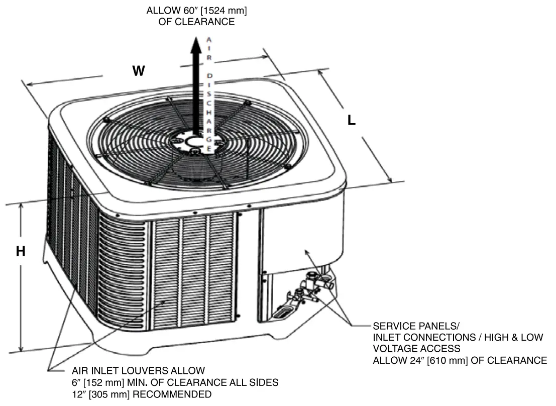
Unit Dimensions
| MODEL NO. | OPERATING | SHIPPING | ||||||||||
| H (Height) | L (Length) | W (Width) | H (Height) | L (Length) | W (Width) | |||||||
| INCHES | mm | INCHES | mm | INCHES | mm | INCHES | mm | INCHES | mm | INCHES | mm | |
| RA15AZ24AJ3 | 27.00 | 686 | 29.75 | 756 | 29.75 | 756 | 28.50 | 724 | 32.38 | 822 | 32.38 | 822 |
| RA15AZ36AJ3 | 27.00 | 686 | 33.75 | 857 | 33.75 | 857 | 28.50 | 724 | 36.38 | 924 | 36.38 | 924 |
| RA15AZ48AJ3 | 31.00 | 787 | 33.75 | 857 | 33.75 | 857 | 32.50 | 826 | 36.38 | 924 | 36.38 | 924 |
| RA15AZ60AJ3 | 31.00 | 787 | 35.75 | 908 | 35.75 | 908 | 32.50 | 826 | 38.38 | 975 | 38.38 | 975 |
[ ] Designates Metric Conversions
CLEARANCES
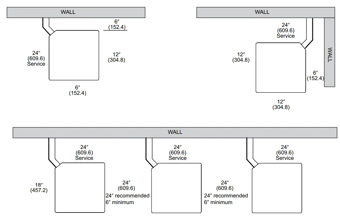
Control Wiring/Application Guidelines
Control Wiring
Application Guidelines
- Intended for outdoor installation with free air inlet and outlet. Outdoor fan external static pressure available is less than 0.01 -in. wc.
- Minimum outdoor operation air temperature for cooling mode without low-ambient operation accessory is 55°F (12.8°C).
- Maximum outdoor operating air temperature is 125°F (51.7°C).
- For reliable operation, unit should be level in all horizontal planes.
- Use only copper wire for electric connections at unit. Aluminum and clad aluminum are not acceptable for the type of connector provided.
- Do not apply capillary tube indoor coils to these units.
- Factory-supplied filter drier must be installed.
Refrigerant Line Size Information
| 15/16 SEER2 VARIABLE SPEED AIR CONDITIONERS | ||||||||
| Unit Size | Allowable Liquid Line Size | Allowable Vapor Line Size | Outdoor Unit ABOVE or BELOW Indoor Unit Equivalent Length (Feet) | |||||
| < 25 | 26-50 | 51-75 | 76-100 | 101-125 | 126-150 | |||
| Maximum Vertical Separation / Capacity Multiplier | ||||||||
| 2.0 Ton **SEE NOTE 3 | 1/4″ | 5/8″ | 25/1.00 | 50/0.99 | 32/0.98 | 40/0.97 | NR | NR |
| 5/16″ | 5/8″ | 25/1.00 | 50/0.99 | 50/0.98 | 50/0.97 | 50/0.96 | 50/0.95 | |
| 3/8″ | 5/8″ | 25/1.00 | 50/0.99 | 50/0.98 | 50/0.97 | 50/0.96 | 50/0.95 | |
| 1/4″ | 3/4″** | 25/1.00 | 50/1.00 | 32/0.99 | 40/0.99 | NR | NR | |
| 5/16″ | 3/4″** | 25/1.00 | 50/1.00 | 50/0.99 | 50/0.99 | 50/0.99 | 50/0.98 | |
| 3/8″ | 3/4″** | 25/1.00 | 50/1.00 | 50/0.99 | 50/0.99 | 50/0.99 | 50/0.98 | |
| 3 Ton | 5/16″ | 5/8″ | 25/0.99 | 50/0.97 | 50/0.95 | 50/0.93 | 37/0.91 | NR |
| 3/8″ | 5/8″ | 25/0.99 | 50/0.97 | 50/0.95 | 50/0.93 | 50/0.91 | NR | |
| 5/16″ | 3/4″ | 25/1.00 | 50/0.99 | 50/0.99 | 50/0.98 | 37/0.97 | 22/0.96 | |
| 3/8″ | 3/4″ | 25/1.00 | 50/0.99 | 50/0.99 | 50/0.98 | 50/0.97 | 50/0.96 | |
| 1/2″ | 3/4″ | 25/1.00 | 50/0.99 | 50/0.99 | 50/0.98 | 50/0.97 | 50/0.96 | |
| 4 Ton | 3/8″ | 3/4″ | 25/0.99 | 50/0.98 | 50/0.97 | 50/0.96 | 50/0.94 | 50/0.93 |
| 1/2″ | 3/4″ | 25/0.99 | 50/0.98 | 50/0.97 | 50/0.96 | 50/0.94 | 50/0.93 | |
| 3/8″ | 7/8″ | 25/1.00 | 50/0.99 | 50/0.99 | 50/0.98 | 50/0.98 | 50/0.97 | |
| 1/2″ | 7/8″ | 25/1.00 | 50/0.99 | 50/0.99 | 50/0.98 | 50/0.98 | 50/0.97 | |
| 5 Ton | 3/8″ | 3/4″ | 25/0.99 | 50/0.97 | 50/0.95 | 50/0.93 | 50/0.91 | NR |
| 1/2″ | 3/4″ | 25/0.99 | 50/0.97 | 50/0.95 | 50/0.93 | 50/0.91 | NR | |
| 3/8″ | 7/8″ | 25/1.00 | 50/0.99 | 50/0.98 | 50/0.98 | 50/0.97 | 38/0.96 | |
| 1/2″ | 7/8″ | 25/1.00 | 50/0.99 | 50/0.98 | 50/0.98 | 50/0.97 | 50/0.96 | |
NOTES:
- Do not exceed 150 ft. linear line length.
- *Do not exceed 50 ft. vertical separation between indoor and outdoor units.
- **3/4″ suction line should only be used for 2 ton systems if outdoor unit is below or at same level as indoor unit to assure proper oil return.
- Always use the smallest liquid line allowable to minimize refrigerant charge.
- Applications shaded in light gray indicate capacity multipliers between 0.90 and 0.96 which are not recommended, but are allowed.
- Applications shaded in dark gray are not recommended due to excessive liquid or suction pressure drop.
[ ] Designates Metric Conversions
Refrigerant Line Size Information
| 15/16 SEER2 VARIABLE SPEED AIR CONDITIONERS | ||||||||
| Unit Size | Allowable Liquid Line Size | Allowable Vapor Line Size | Outdoor Unit ABOVE or BELOW Indoor Unit Equivalent Length (Meters) | |||||
| < 25 | 26-50 | 51-75 | 76-100 | 101-125 | 126-150 | |||
| Maximum Vertical Separation / Capacity Multiplier | ||||||||
| 2.0 Ton **SEE NOTE 3 | 6.35 [1/4] | 15.88 [5/8] | 8/1.00 | 15/0.99 | 1/0.98 | 10/0.97 | NR | NR |
| 7.94 [5/16] | 15.88 [5/8] | 8/1.00 | 15/0.99 | 15/0.98 | 15/0.97 | 15/0.96 | 15/0.95 | |
| 9.53 [3/8] | 15.88 [5/8] | 8/1.00 | 15/0.99 | 15/0.98 | 15/0.97 | 15/0.96 | 15/0.95 | |
| 6.35 [1/4] | 19.05 [3/4]** | 8/1.00 | 15/0.99 | 10/0.99 | 1/0.99 | NR | NR | |
| 7.94 [5/16] | 19.05 [3/4]** | 8/1.00 | 15/0.99 | 15/0.99 | 15/0.99 | 15/0.99 | 15/0.98 | |
| 9.53 [3/8] | 19.05 [3/4]** | 8/1.00 | 15/0.99 | 15/0.99 | 15/0.99 | 15/0.99 | 15/0.98 | |
| 3 Ton | 7.94 [5/16] | 15.88 [5/8] | 8/0.99 | 15/0.97 | 15/0.95 | 15/0.93 | 11/0.91 | NR |
| 9.53 [3/8] | 15.88 [5/8] | 8/0.99 | 15/0.97 | 15/0.95 | 15/0.93 | 15/0.91 | NR | |
| 7.94 [5/16] | 19.05 [3/4] | 8/1.00 | 15/0.99 | 15/0.99 | 15/0.98 | 11/0.97 | 7/0.96 | |
| 9.53 [3/8] | 19.05 [3/4] | 8/1.00 | 15/0.99 | 15/0.99 | 15/0.98 | 15/0.97 | 15/0.96 | |
| 12.7 [1/2] | 19.05 [3/4] | 8/1.00 | 15/0.99 | 15/0.99 | 15/0.98 | 15/0.97 | 15/0.96 | |
| 4 Ton | 9.53 [3/8] | 19.05 [3/4] | 8/0.99 | 15/0.98 | 15/0.97 | 15/0.96 | 15/0.94 | 15/0.93 |
| 12.7 [1/2] | 19.05 [3/4] | 8/0.99 | 15/0.98 | 15/0.97 | 15/0.96 | 15/0.94 | 15/0.93 | |
| 9.53 [3/8] | 22.23 [7/8] | 8/1.00 | 15/0.99 | 15/0.99 | 15/0.98 | 15/0.98 | 15/0.97 | |
| 12.7 [1/2] | 22.23 [7/8] | 8/1.00 | 15/0.99 | 15/0.99 | 15/0.98 | 15/0.98 | 15/0.97 | |
| 5 Ton | 9.53 [3/8] | 19.05 [3/4] | 8/0.99 | 15/0.97 | 15/0.95 | 15/0.93 | 15/0.91 | NR |
| 12.7 [1/2] | 19.05 [3/4] | 8/0.99 | 15/0.97 | 15/0.95 | 15/0.93 | 15/0.91 | NR | |
| 9.53 [3/8] | 22.23 [7/8] | 8/1.00 | 15/0.99 | 15/0.98 | 15/0.98 | 15/0.97 | 12/0.96 | |
| 12.7 [1/2] | 22.23 [7/8] | 8/1.00 | 15/0.99 | 15/0.98 | 15/0.98 | 15/0.97 | 15/0.97 | |
NOTES:
- Do not exceed 46 meters linear line length.
- *Do not exceed 15 meters vertical separation between indoor and outdoor units.
- **19.05mm [3/4 in.] vapor line should only be used for 2 ton systems if outdoor unit is below or at same level as indoor unit to assure proper oil return.
- Always use the smallest liquid line allowable to minimize refrigerant charge.
- Applications shaded in light gray indicate capacity multipliers between 0.90 and 0.96 which are not recommended, but are allowed.
- Applications shaded in dark gray are not recommended due to excessive liquid or suction pressure drop.
| Additional Oil, Oz. | |||||||||||
| Lineset Length | 50 | 60 | 70 | 80 | 90 | 100 | 110 | 120 | 130 | 140 | 150 |
| 2T | N/A | N/A | N/A | N/A | N/A | 1 | 2 | 3 | 5 | 6 | 7 |
| 3T | N/A | N/A | N/A | N/A | N/A | N/A | 1 | 2 | 3 | 5 | 6 |
| 4T | N/A | N/A | N/A | N/A | N/A | N/A | N/A | N/A | N/A | N/A | N/A |
| 5T | N/A | N/A | N/A | N/A | N/A | N/A | N/A | N/A | N/A | N/A | N/A |
Performance Data
Performance Data @ AHRI Standard Conditions – Cooling
| DESIGNATED TESTED COMBINATION (DTC) | |||||||
| Outdoor Unit | Air Handler | Total Capacity BTU/H [kW] | Net Sensible BTU/H [kW] | Net Latent BTU/H [kW] | SEER2 | EER2 | Indoor CFM [L/s] |
| RA15AZ24AJ3 | RH3VZ2417STACN | 22800 [6.7] | 17600 [5.2] | 5200 [1.5] | 15.2 | 9.8 | 750 [354.0] |
| RA15AZ36AJ3 | RH3VZ3617STACN | 34200 [10.0] | 26600 [7.8] | 7600 [2.2] | 15.2 | 9.8 | 1125 [530.9] |
| RA15AZ48AJ3 | RH3VZ4821STACN | 45500 [13.3] | 35500 [10.4] | 10000 [2.9] | 15.2 | 9.8 | 1425 [672.5] |
| RA15AZ60AJ3 | RH3VZ6024STACN | 55500 [16.3] | 43000 [12.6] | 12500 [3.7] | 15.2 | 9.8 | 1675 [790.5) |
NOTE: This data includes DTC (Designated Test Combination) ratings and is for reference purposes only. A full listing of official ratings and system match-ups, along with
downloadable certificates, can be accessed from the AHRI website: www.ahridirectory.org.
[ ] Designates Metric Conversions
Integrated Controls
EcoNet® is smart, new technology developed exclusively by Rheem that allows Heating, Cooling, and Water Heating products to communicate with each other on one integrated network.
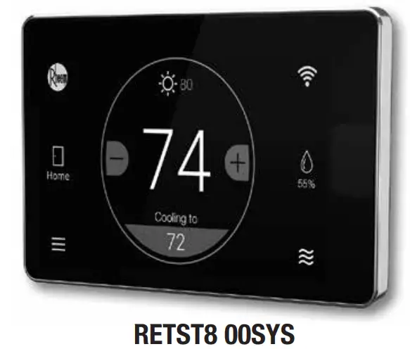
THE ECONET® SMART THERMOSTAT
BUILT-IN WIFI
4.3″ LCD TOUCH SCREEN
LOCAL WEATHER – Current conditions plus 6-day forecast
5 OPERATING MODES – Heat, Cool, Auto, Emergency Heat and Fan Only
7-DAY PROGRAMMABLE SCHEDULE – Offers comfort without thought
ONE-TOUCH AWAY – Quickly switch to your energy-saving away preferences
VACATION SCHEDULING – Allows you to save while you’re away and come home to comfort
STANDBY SCREEN – Displays indoor temperature and current weather
OPERATIONAL FEATURES
AUTOMATIC CHANGEOVER – Transitions between heating and cooling automatically to keep the house comfortable
INTEGRATED WATER CONTROL – Enables easy water heater management
SMOOTH ARRIVAL – Prompts the system to start ahead of schedule to ensure the home is at the desired temperature at the scheduled time
HUMIDITY CONTROL – Supports humidifier accessories or over-cool based dehumidification
DETAILED OPERATING STATUS – View pertinent equipment status information and run times
CONTINUOUS FAN – Offers 5 speeds (Low, Medium Low, Medium, Medium High, High)
SHORT-CYCLE PROTECTION – Avoids damage to equipment from short run cycles
MONITORING & REMOTE CONTROL FEATURES
ACTIVE MONITORING – Alerts to problems that need immediate attention
REMOTE CONTROL – Allows adjusting of comfort and settings from anywhere using a mobile device
SERVICE ALERTS – Sends routine maintenance reminders
AIR FILTER MONITORING – Detects when it’s time to replace the air filter
ALARM HISTORY – Displays time-stamped alarm codes with clear descriptions
GENERAL TERMS OF LIMITED WARRANTY*
Rheem will furnish a replacement for any part of this product which fails in normal use and service within the applicable period stated, in accordance with the terms of the limited warranty.
*For complete details of the Limited and Conditional Warranties, including applicable terms and conditions, contact your local contractor or the Manufacturer for a copy of the product warranty certificate.
Conditional Parts
(Registration Required) …………………………….. Ten (10) Years
Before proceeding with installation, refer to installation instructions packaged with each model, as well as complying with all Federal, State, Provincial, and Local codes, regulations, and practices.
© 2022 Rheem Manufacturing Company. Rheem trademarks owned by Rheem Manufacturing Company.
In keeping with its policy of continuous progress and product improvement, Rheem reserves the right to make changes without notice.
![]()
Rheem Heating, Cooling & Water Heating • 5600 Old Greenwood Road
Fort Smith, Arkansas 72908 • www.rheem.com
Rheem Canada Ltd./Ltée • 125 Edgeware Road, Unit 1
Brampton, Ontario • L6Y 0P5 • rheem.ca.com
PRINTED IN U.S.A. 11/22 QG FORM NO. A11-336 REV. 2


