![]() CAS-5A Amateur Radio Satellite
CAS-5A Amateur Radio Satellite
User’s Manual
Ver. 1.0
Fengtai OSCAR-118![]() BA1DU, Alan Kung
BA1DU, Alan Kung
2022-12-15
CAS-5A Amateur Radio Satellite
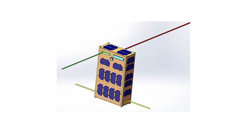
The CAMSAT CAS-5A amateur radio satellite was piggybacked on the Smart Dragon-3 Y1 launch vehicle and launched from the sea launch platform in the Yellow Sea at UTC 06:35:02 on December 9, 2022. After 724 seconds, the satellite successfully separated from the launch vehicle and entered the intended orbit. The satellite orbit is a circular sun-synchronous orbit with an altitude of 543 kilometers and an inclination of 97.53 degrees, the running cycle is 95.575minutes. AMSAT has designated CAS-5A satellite as Fengtai-OSCAR 118 (FO-118).  The functions of CAS-5A satellite include UHF CW telemetry beacon, GMSK telemetry data transmission, V/U mode linear transponder, V/U mode FM transponder, H/U mode linear transponder, three visible light band space cameras.
 After the satellite completes the in-orbit test and works normally, the space camera photo download will be open to amateur radio enthusiasts all over the world. When the relevant remote control command is received by the satellite, the GMSK telemetry channel will be used to downlink the photo catalog and photo data, and the telemetry data will stop sending at that time.
CAS-5A satellite adopts a 6U CubeSat structure with a mass of about 7kg, an on-orbit envelope size of 366x226x100mm (antennas not included) with six sides body-mounted solar panels and a three-axis stabilized attitude control system is used, long-term power consumption is about 10 Watts.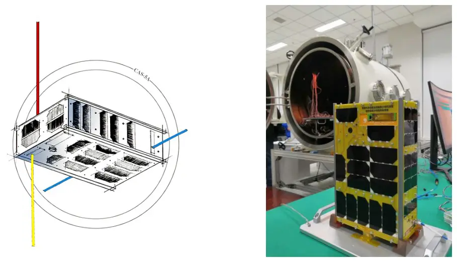
Technical specifications:
- VHF antenna: 1/4 wavelength whip antenna
- UHF antenna: two 1/4 wavelength whip antenna
- HF antenna: whip antenna
- CW telemetry beacon:
- Frequency: 435.570MHz ●RF power: 20dBm ●CW rate: 22wpm
- GMSK telemetry:
- Frequency: 435.650MHz ●RF power: 25dBm ●Data rate: 4800/9600bps
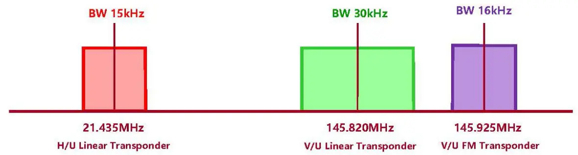
- V/U mode linear transponder:
- Uplink frequency: 145.820MHz ●Downlink frequency: 435.540MHz
- RF power: 23dBm ●Bandwidth: 30kHz ●Spectrum inverted
- V/U mode FM transponder:
- Uplink frequency: 145.925MHz ●Downlink frequency: 435.600MHz
- RF power: 23dBm ●Bandwidth: 16kHz
- H/U mode linear transponder:
- Uplink frequency: 21.435MHz ●Downlink frequency: 435.505MHz
- RF power: 23dBm ●Bandwidth: 15kHz ●Spectrum normal
- Photo download remote control:
- Frequency: 145.975MHz
- RF modulation: FM, frequency deviation ±3kHz
- Subcarrier: DTMF ( dual-tone multi-frequency )
 CAS-5A Satellite receiving spectrum
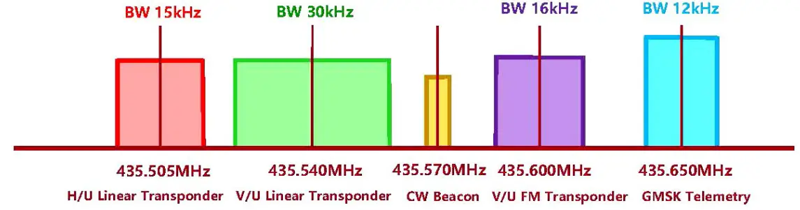 CAS-5A Satellite transmitting spectrum
CW Telemetry Beacon Description:
1. CW beacon sending sequence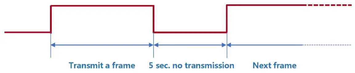
- Send stop interval time: 5s
- CW sending rate: 22wpm
2. CW beacon frame format
Sending order | Sending content | Description | Remarks |
| 1 | BJ1SO | Satellite call sign | Send in standard Morse code |
| 2 | CAS5A | Telemetry information start identifier | |
| 3 | CAS5A | Telemetry information start identifier | |
| 4 | CH1 | Telemetry channel 1 | |
| 5 | CH2 ~ CH31 | Telemetry channel 2~Telemetry channel 31 | Send this channel information, see [Digital Code Table] below |
| 6 | CAMSAT | Telemetry information end flag | Send in standard Morse code |
| 7 | CAMSAT | Telemetry information end flag |
The telemetry data (CH2 to CH31) are coded as follows:
Digital Code Table
Digital | Code |
| 0 | T |
| 1 | A |
| 2 | U |
| 3 | V |
| 4 | 4 |
| 5 | E |
| 6 | 6 |
| 7 | B |
| 8 | D |
| 9 | N |
3. CW beacon telemetry information and data analysis
Channel | Parameter name | Type | Value range | Parsing algorithm | Unit | |
Mini. | Max. | |||||
| CH1 | Current operating mode |
state |
000 |
999 | XYZ: X: 4=4800bps, 9=9600bps GMSK telemetry rate YZ: 01 = All asleep 02 = Beacon on (send every 5 minutes) 03 = Beacon on (send every 5 seconds from mode 3 to mode 10) 04 = Beacon on + AX.25 telemetry 05 = Beacon on + AX.25 telemetry + V/U linear transponder 06 = Beacon on + AX.25 telemetry + V/U linear transponder + H/U linear transponder 07 = Beacon on + AX.25 telemetry + V/U linear transponder + FM transponder + H/U linear transponder 08 = Beacon on + AX.25 telemetry + V/U linear transponder + FM transponder + H/U linear transponder + H/T linear transponde 09 = Beacon on + AX.25 telemetry + V/U linear transponder + FM transponder + H/U linear transponder + H/T linear transponder + heater 1 10 = Beacon on + AX.25 telemetry + V/U linear transponder + FM transponder + H/U linear transponder + H/T linear transponder + heater 1 + heater 2 (H/T linear transponder is not valid in CAS-5A) |
— |
| CH2 | CW telemetry frame transmission counter | data | 000 | 255 | Every time a frame is sent, the CW telemetry frame counter is incremented by 1, and starts counting from 000 when it is full | Time |
| CH3 | Remote control command receiving counter | data | 000 | 255 | Every time a remote control command is received, the counter is incremented by 1, and start counting from 000 when it is full | Time |
| CH4 | Primary power supply voltage | data | 000 | 999 | U=N/10 | V |
| CH5 | 3.8V bus voltage | data | 000 | 999 | U=N/100 | V |
| CH6 | 5.5V bus voltage | data | 000 | 999 | U=N/100 | V |
| CH7 | Battery voltage | data | 000 | 999 | U=N/10 | V |
| CH8 | Solar array current | data | 000 | 999 | I=N/100 | A |
| CH9 | Primary bus current | data | 000 | 999 | I=N/100 | A |
| CH10 | Total load current | data | 000 | 999 | I=N/100 | A |
| CH11 | VHF receiver current | data | 000 | 999 | I=N | mA |
| CH12 | UHF transmitter1 current | data | 000 | 999 | I=N | mA |
| CH13 | UHF transmitter2 current | data | 000 | 999 | I=N | mA |
| CH14 | Reserved | data | 000 | 999 | I=N | mA |
| CH15 | VHF AGC voltage | data | 000 | 999 | U=N/100 | V |
| CH16 | UHF transmitter1 RF power | data | 00 | 99 | P=600+N | mW |
| CH17 | UHF transmitter2 RF power | data | 000 | 999 | P=N/100 | mW |
| CH18 | Reserved | data | 000 | 999 | P=N/100 | mW |
| CH19 | IHU temperature | data | 000 | 999 | XYZ When X is 0-2, it represents a positive temperature; X is 3-4, it represents a negative temperature. | ℃ |
| CH20 | Battery 1 temperature | data | 000 | 999 | ℃ | |
| CH21 | Battery 2 temperature | data | 000 | 999 | ℃ | |
| CH22 | UHF1 PA temperature | data | 000 | 999 | ℃ |
| CH23 | UHF2 PA temperature | data | 000 | 999 | T=N (N≤300) T=-1x (N-300) (N>300) For example: 000 : 0℃ 025 : 25℃ 125 : 125℃ 301 : -1℃ 311 : -11℃ 391 : -91℃ 421 : -121℃ | ℃ |
| CH24 | Camera 3 temperature | data | 000 | 999 | ℃ | |
| CH25 | Camera 1 temperature | data | 000 | 999 | ℃ | |
| CH26 | +X Cabin Plate Inner Temperature | data | 000 | 999 | ℃ | |
| CH27 | -X Cabin Plate Inner Temperature | data | 000 | 999 | ℃ | |
| CH28 | PCDU Temperature | data | 000 | 999 | ℃ | |
| CH29 | DC/DC Temperature | data | 000 | 999 | ℃ | |
| CH30 | +Z Cabin Plate Inner Temperature | data | 000 | 999 | ℃ | |
| CH31 | -Z Cabin Plate Inner Temperature | data | 000 | 999 | ℃ |
GMSK telemetry data:
1. GMSK telemetry frame format and communication protocol
CAS-5A satellite GMSK telemetry data is sent in the AX.25 UI frame format. Callsign is BJ1SO.
The user data of each frame is 167 bytes, and the allocation is as follows:
Function code | Telemetry data content |
| 7Byte | 160Byte |
| W0~W6:0x0100010001007E | W7~W166 |
2. GMSK telemetry data format and analysis method
Sending | Starting position | Data length | Telemetry data function description | Telemetry data parsing algorithm |
| 1 | W7 | 6Byte | Satellite time | W1-Year: 00~99, representing 2000~2099 W2-Month: 01~12, representing January to December W3-Day: 01~31, representing 1st~31st W4-Hour: 00~23, representing 0:00~23:00 W5-minute: 00~59, representing 0 minutes~59 minutes W6-second: 00~59, representing 0 seconds~59 seconds |
| 2 | W13 | 1Byte | IHU total reset counter | W1 is an integer. Restart counting from 0 after counting up |
| Range: 0~255 | ||||
| 3 | W14 | 1Byte | Battery status | b7~b1: reserved, all values are 0 b3: Battery heater 2 switch state (0 off/1 on) b2: Battery heater 1 switch state (0 off/1 on) b1: Battery discharge switch state (0 off/1 on) b0: Battery discharge switch off allowable state (0 energy disabled/1 enabled) |
| 4 | W15 | 1Byte | Remote control frame reception counter | W1 is an integer. Restart counting from 0 after counting up Range: 0~255 |
| 5 | W16 | 1Byte | Remote control command execution counter | W1 is an integer. Restart counting from 0 after counting up Range: 0~255 |
| 6 | W17 | 1Byte | Telemetry Frame Transmission Counter | W1 is an integer. Restart counting from 0 after counting up Range: 0~255 |
| 7 | W18 | 1Byte | IHU status 1 | b7: IHU flash2 read and write failure (0 normal/1 fault) b6: Remote control command CRC correctly identified (0 error/1 correct) b5: IHU flash1 read and write failure (0 normal/1 failure) b4: CPU I/O acquisition watchdog switch flag (0 off/1 on) b3: reserved, value 0 b2: ADC Software Watchdog Switch Flag (0 Off/1 On) b1: Temperature measurement software watchdog switch sign (0 off/1 on) b0: Remote control software watchdog switch sign (0 off/1 on) |
| 8 | W19 | 1Byte | Reserved | W1 is an integer. Restart counting from 0 after counting up Range: 0~255 |
| 9 | W20 | 1Byte | I2C bus status | b7~b5: reserved, all values are 0 b4: Temperature1-I2C fault (0 normal/1 fault) b3: Temperature2-I2C fault (0 normal/1 fault) b2: Temperature3-I2C fault (0 normal/1 fault) b1: ADC-I2C fault (0 normal/1 fault) b0: Clock-I2C fault (0 normal/1 fault) |
| 10 | W21 | 1Byte | Reserved | W1 is an integer. Restart counting from 0 after counting up Range: 0~255 |
| 11 | W22 | 1Byte | Reserved | W1 is an integer. Restart counting from 0 after counting up Range: 0~255 |
| 12 | W23 | 1Byte | Reserved | W1 is an integer. Restart counting from 0 after counting up Range: 0~255 |
| 13 | W24 | 1Byte | IHU status 2 | b7: Board-to-board communication failure (0 normal/1 fault) b6: Flash2 read and write failure of the camera board (0 normal/1 failure) b5: Flash1 read and write failure of the camera board (0 normal/1 failure) B4: Antenna deployment master switch state (0 off/1 on) b3: UHF antenna 1 deployment state (0 undeployed/1 deployed) b2: UHF antenna 2 deployment state (0 undeployed/1 deployed) b1: VHF antenna deployment status (0 undeployed/1 deployed) b0: HF antenna deployment state (0 undeployed/1 deployed) |
| 14 | W25 | 1Byte | IHU status 3 | b7~b3: Reserved, all values are 0 b2: Satellite Separation Status (0 Not Separated /1 Separated) b1: Reserved, value 0 |
| b0: Delay telemetry switch state (0 off/1 on) | ||||
| 15 | W26 | 1Byte | +X cabin plate inner temperature | b7 of W1 is the sign bit, 0 is positive, 1 is negative; b6~b0 are numerical bits Range: -100~+100(℃) |
| 16 | W27 | 1Byte | -X cabin plate inner temperature | b7 of W1 is the sign bit, 0 is positive, 1 is negative; b6~b0 are numerical bits Range: -100~+100(℃) |
| 17 | W28 | 1Byte | PCDU Temperature | b7 of W1 is the sign bit, 0 is positive, 1 is negative; b6~b0 are numerical bits Range: -100~+100(℃) |
| 18 | W29 | 1Byte | DC/DC Temperature | b7 of W1 is the sign bit, 0 is positive, 1 is negative; b6~b0 are numerical bits Range: -100~+100(℃) |
| 19 | W30 | 1Byte | +Z cabin plate inner temperature | b7 of W1 is the sign bit, 0 is positive, 1 is negative; b6~b0 are numerical bits Range: -100~+100(℃) |
| 20 | W31 | 1Byte | -Z cabin plate inner temperature | b7 of W1 is the sign bit, 0 is positive, 1 is negative; b6~b0 are numerical bits Range: -100~+100(℃) |
| 21 | W32 | 1Byte | +X solar array temperature | b7 of W1 is the sign bit, 0 is positive, 1 is negative; b6~b0 are numerical bits Range: -100~+100(℃) |
| 22 | W33 | 1Byte | -X solar array temperature | b7 of W1 is the sign bit, 0 is positive, 1 is negative; b6~b0 are numerical bits Range: -100~+100(℃) |
| 23 | W34 | 1Byte | +Y solar array temperature | b7 of W1 is the sign bit, 0 is positive, 1 is negative; b6~b0 are numerical bits Range: -100~+100(℃) |
| 24 | W35 | 1Byte | -Y solar array temperature | b7 of W1 is the sign bit, 0 is positive, 1 is negative; b6~b0 are numerical bits Range: -100~+100(℃) |
| 25 | W36 | 1Byte | +Z solar array temperature | b7 of W1 is the sign bit, 0 is positive, 1 is negative; b6~b0 are numerical bits Range: -100~+100(℃) |
| 26 | W37 | 1Byte | -Z solar array temperature | b7 of W1 is the sign bit, 0 is positive, 1 is negative; b6~b0 are numerical bits Range: -100~+100(℃) |
| 27 | W38 | 1Byte | Battery pack 1 temperature 1 | b7 of W1 is the sign bit, 0 is positive, 1 is negative; b6~b0 are numerical bits Range: -100~+100(℃) |
| 28 | W39 | 1Byte | Battery pack 1 temperature 2 | b7 of W1 is the sign bit, 0 is positive, 1 is negative; b6~b0 are numerical bits Range: -100~+100(℃) |
| 29 | W40 | 1Byte | Battery pack 2 temperature 3 | b7 of W1 is the sign bit, 0 is positive, 1 is negative; b6~b0 are numerical bits Range: -100~+100(℃) |
| 30 | W41 | 1Byte | Battery pack 2 temperature 4 | b7 of W1 is the sign bit, 0 is positive, 1 is negative; b6~b0 are numerical bits Range: -100~+100(℃) |
| 31 | W42 | 1Byte | IHU temperature | b7 of W1 is the sign bit, 0 is positive, 1 is negative; b6~b0 are numerical bits Range: -100~+100(℃) |
| 32 | W43 | 1Byte | UHF1 PA temperature | b7 of W1 is the sign bit, 0 is positive, 1 is negative; b6~b0 are numerical bits Range: -100~+100(℃) |
| 33 | W44 | 1Byte | Camera 3 temperature | b7 of W1 is the sign bit, 0 is positive, 1 is negative; b6~b0 are numerical bits Range: -100~+100(℃) |
| 34 | W45 | 1Byte | Camera 1 temperature | b7 of W1 is the sign bit, 0 is positive, 1 is negative; b6~b0 are numerical bits Range: -100~+100(℃) |
| 35 | W46 | 1Byte | Camera 2 temperature | b7 of W1 is the sign bit, 0 is positive, 1 is negative; b6~b0 are numerical bits Range: -100~+100(℃) |
| 36 | W47 | 1Byte | UHF2 PA temperature | b7 of W1 is the sign bit, 0 is positive, 1 is negative; b6~b0 are numerical bits Range: -100~+100(℃) |
| 37 | W48 | 2Byte | Battery voltage | W1 is the integer part, W2 is the decimal part (1 decimal place) |
| Range: 0~15.0(V) | ||||
| 38 | W50 | 2Byte | Primary power supply voltage (12V) | W1 is the integer part, W2 is the decimal part (1 decimal place) Range: 0~15.0(V) |
| 39 | W52 | 2Byte | 3.8V bus voltage | W1 is the integer part, W2 is the decimal part (2 decimal places) Range: 0~5.00(V) |
| 40 | W54 | 2Byte | 5.5V bus voltage | W1 is the integer part, W2 is the decimal part (2 decimal places) Range: 0~10.00(V) |
| 41 | W56 | 2Byte | IHU 3.3V voltage | W1 is the integer part, W2 is the decimal part (2 decimal places) Range: 0~5.00(V) |
| 42 | W58 | 2Byte | Total solar array current | W1W2 is an integer Range: 0~3000(mA) |
| 43 | W60 | 2Byte | Primary bus current | W1W2 is an integer Range: 0~2000(mA) |
| 44 | W62 | 2Byte | Total load current | W1W2 is an integer Range: 0~1000(mA) |
| 45 | W64 | 2Byte | IHU current | W1W2 is an integer Range: 0~500(mA) |
| 46 | W66 | 2Byte | Reserved | W1W2 is an integer Range: 0~1000(mA) |
| 47 | W68 | 2Byte | HF receiver current | W1W2 is an integer Range: 0~1000(mA) |
| 48 | W70 | 2Byte | Reserved | W1W2 is an integer Range: 0~2000(mW) |
| 49 | W72 | 2Byte | UHF transmitter 2 current | W1W2 is an integer Range: 0~1000(mA) |
| 50 | W74 | 2Byte | H/T AGC voltage | W1 is the integer part, W2 is the decimal part (2 decimal place) Range: 0~5.00(V) |
| 51 | W76 | 2Byte | UHF transmitter 1 current | W1W2 is an integer Range: 0~1000(mA) |
| 52 | W78 | 2Byte | UHF1 RF power | W1W2 is an integer Range: 0~3000(mW) |
| 53 | W80 | 2Byte | UHF2 RF power | W1W2 is an integer Range: 0~3000(mW) |
| 54 | W82 | 2Byte | VHF receiver current | W1W2 is an integer Range: 0~1000(mA) |
| 55 | W84 | 2Byte | VHF AGC voltage | W1 is the integer part, W2 is the decimal part (2 decimal place) Range: 0~5.00(V) |
| 56 | W86 | 6Byte | Delayed telemetry start time | W1-Year: 0~99, representing 2000~2099 W2-Month: 01~12, representing January to December W3-Day: 01~31, representing 1st~31st W4-Hour: 00~23, representing 0:00~23:00 W5-minute: 00~59, representing 0 minute~59 minutes W6-second: 00~59, representing 0 second~59 seconds |
| 57 | W92 | 3Byte | Delayed telemetry interval setting | W1-Hour: 00~23, representing 0:00~23:00 W2-Minute: 00~59, representing 0 minute~59 minutes W3-second: 00~59, representing 0 second~59 seconds |
| 58 | W95 | 3Byte | Frequency of delayed telemetry setting | W1W2W3 is an integer Range: 0 ~ 16777215 |
| 59 | W98 | 2Byte | The camera controller operating current | W1W2 is an integer Range: 0~500(mA) |
| 60 | W100 | 2Byte | The operating voltage of the camera controller | W1 is the integer part, W2 is the decimal part (2 decimal place) Range: 0~5.00(V) |
| 61 | W102 | 2Byte | Total camera current | W1W2 is an integer Range: 0~2000(mA) |
| 62 | W104 | 1Byte | Camera working status | b7: Camera controller power switch status (0 off/1 on) b6: reserved, value 0 b5: Camera 1 power switch status (0 off/1 on) b4: Camera 1 delayed photography switch status (0 off/1 on) b3: Camera 2 power switch status (0 off/1 on) b2: Camera 2 delayed photography switch status (0 off/1 on) b1: Camera 3 power switch status (0 off/1 on) b0: Camera 3 delayed photography switch status (0 off/1 on) |
| 63 | W105 | 2Byte | Camera 1 photo counter | W1W2 is an integer Range: 0 ~ 2047 |
| 64 | W107 | 2Byte | Camera 2 photo counter | W1W2 is an integer Range: 0 ~ 2047 |
| 65 | W109 | 2Byte | Camera 3 photo counter | W1W2 is an integer Range: 0 ~ 2047 |
| 66 | W111 | 6Byte | Camera 1 Delayed Photography start time | W1-Year: 0~99, representing 2000~2099 |
| W2-Month: 01~12, representing January to December W3-Day: 01~31, representing 1st~31st W4-Hour: 00~23, representing 0:00~23:00 W5-minute: 00~59, representing 0 minute~59 minutes W6-second: 00~59, representing 0 second~59 seconds | ||||
| 67 | W117 | 3Byte | Camera 1 Delayed Photography interval setting | W1-Hour: 00~23, representing 0:00~23:00 W2-Minute: 00~59, representing 0 minute~59 minutes W3-second: 00~59, representing 0 second~59 seconds |
| 68 | W120 | 1Byte | Camera 1 Frequency of delayed Photography setting | W1 is an integer Range: 0 ~ 60 |
| 69 | W121 | 6Byte | Camera 2 Delayed Photography start time | W1-Year: 0~99, representing 2000~2099 W2-Month: 01~12, representing January to December W3-Day: 01~31, representing 1st~31st W4-Hour: 00~23, representing 0:00~23:00 W5-minute: 00~59, representing 0 minute~59 minutes W6-second: 00~59, representing 0 second~59 seconds |
| 70 | W127 | 3Byte | Camera 2 Delayed Photography interval setting | W1-Hour: 00~23, representing 0:00~23:00 W2-Minute: 00~59, representing 0 minute~59 minutes W3-second: 00~59, representing 0 second~59 seconds |
| 71 | W130 | 1Byte | Camera 2 Frequency of delayed Photography setting | W1 is an integer Range: 0 ~ 60 |
| 72 | W131 | 6Byte | Camera 3 Delayed Photography start time | W1-Year: 0~99, representing 2000~2099 |
| W2-Month: 01~12, representing January to December W3-Day: 01~31, representing 1st~31st W4-Hour: 00~23, representing 0:00~23:00 W5-minute: 00~59, representing 0 minute~59 minutes W6-second: 00~59, representing 0 second~59 seconds | ||||
| 73 | W137 | 3Byte | Camera 3 Delayed Photography interval setting | W1-Hour: 00~23, representing 0:00~23:00 W2-Minute: 00~59, representing 0 minute~59 minutes W3-second: 00~59, representing 0 second~59 seconds |
| 74 | W140 | 1Byte | Camera 3 Frequency of delayed Photography setting | W1 is an integer Range: 0 ~ 60 |
| 75 | W141 | 1Byte | Satellite current operating mode | W1 is an integer Range: 0 ~ 10 01 = All asleep 02 = Beacon on (send every 5 minutes) 03 = Beacon on (send every 5 seconds from mode 3 to mode 10) 04 = Beacon on + AX.25 telemetry 05 = Beacon on + AX.25 telemetry + V/U linear transponder 06 = Beacon on + AX.25 telemetry + V/U linear transponder + H/U linear transponder 07 = Beacon on + AX.25 telemetry + V/U linear transponder + FM transponder + H/U linear transponder 08 = Beacon on + AX.25 telemetry + V/U linear transponder + FM transponder + H/U linear transponder + H/T linear transponder 09 = Beacon on + AX.25 telemetry + V/U linear transponder + FM transponder + H/U linear transponder + H/T linear transponder + heater 1 10 = Beacon on + AX.25 telemetry + V/U linear transponder + FM transponder + H/U |
| linear transponder + H/T linear transponder + heater 1 + heater 2 (H/T linear transponder is not valid in CAS-5A) | ||||
| 76 | W142 | 2Byte | Satellite device switch status | b15~b10: Reserved, all values are 0 b9: GMSK telemetry data rate (0-9.6kbps/1-4.8kbps) b8: RF power status (0 low power / 1 high power) b7: V/U FM transponder switch state (0 off/1 on) b6: V/U linear transponder switching state (0 off/1 on) b5: UHF beacon switch status (0 off/1 on) b4: UHF GMSK telemetry switch state (0 off/1 on) b3: H/U linear transponder switching state (0 off/1 on) b2: H/T linear transponder switching state (0 off/1 on) b1: HF beacon switch status (0 off/1 on) b0: Working mode status (0 auto/1 manual) |
| 77 | W144 | 6Byte | 48 hours reset time | W1-Year: 00~99, representing 2000~2099 W2-Month: 01~12, representing January to December W3-Day: 01~31, representing 1st~31st W4-Hour: 00~23, representing 0:00~23:00 W5-minute: 00~59, representing 0 minutes~59 minutes W6-second: 00~59, representing 0 seconds~59 seconds |
| 78 | W150 | 2Byte | Attitude quaternion q0 | W1W2:Q0L Q0H q0=((Q0H<<8)|Q0L)/32768 |
| 79 | W152 | 2Byte | Attitude quaternion q1 | W1W2:Q1L Q1H q1=((Q1H<<8)|Q1L)/32768 |
| 80 | W154 | 2Byte | Attitude quaternion q2 | W1W2:Q2L Q2H q2=((Q2H<<8)|Q2L)/32768 |
| 81 | W156 | 2Byte | Attitude quaternion q3 | W1W2:Q3L Q3H q3=((Q3H<<8)|Q3L)/32768 |
| 82 | W158 | 1Byte | Camera 1 resolution | W1 is an integer Range: 0 ~ 7 0:800×480;1:1280×720;2:320×240; 3:1440×896;4:640×480;5:1920×1080; 6:800×600;7:1024×768 |
| 83 | W159 | 1Byte | Camera 1 image quality | W1 is an integer Range: 0 ~ 2 0: Highest quality; 1: Medium quality; 2: Low quality |
| 84 | W160 | 1Byte | Camera 2 resolution | W1 is an integer Range: 0 ~ 7 0:800×480;1:1280×720;2:320×240; 3:1440×896;4:640×480;5:1920×1080; 6:800×600;7:1024×768 |
| 85 | W161 | 1Byte | Camera 2 image quality | W1 is an integer Range: 0 ~ 2 0: Highest quality; 1: Medium quality; 2: Low quality |
| 86 | W162 | 1Byte | Camera 3 resolution | W1 is an integer Range: 0 ~ 7 0:800×480;1:1280×720;2:320×240; 3:1440×896;4:640×480;5:1920×1080; 6:800×600;7:1024×768 |
| 87 | W163 | 1Byte | Camera 3 image quality | W1 is an integer Range: 0 ~ 2 0: Highest quality; 1: Medium quality; 2: Low quality |
| 88 | W164 | 3Byte | The current delayed telemetry interval setting | W1-Hour: 00~23, representing 0:00~23:00 W2-Minute: 00~59, representing 0 minute~59 minutes W3-second: 00~59, representing 0 second~59 seconds |
Space camera photo data:
The application will be available later.
![]()
 Amateur Radio Satellite User Manual")
amateur Radio Satellite User Manual")


