CAMSAT XW-3 (CAS-9) Amateur Radio Satellite
CAMSAT XW-3(CAS-9) amateur radio satellite will be launched by Chinese CZ-4C Y39 launch vehicle on December 25, 2021 from the Taiyuan Satellite Launch Center in China. XW-3(CAS-9) satellite will be piggybacked on the rocket with primary payload ZY-1(02E) satellite. The satellite orbit is a circular sun-synchronous orbit with an altitude of 770.1 kilometers and an inclination of 98.58 degrees, the running cycle is 100.14 minutes.
The functions of XW-3(CAS-9) satellite include UHF CW telemetry beacon, GMSK telemetry data transmission, V/U mode linear transponder, a visible light band space camera and an experimental thermoelectric generator for high school students. After the satellite completes the in-orbit test and works normally, the space camera photo download will be open to amateur radio enthusiasts all over the world. When the relevant remote control command is received by the satellite, the GMSK telemetry channel will be used to downlink the photo storage information and photo data, and the telemetry data will stop sending at that time.
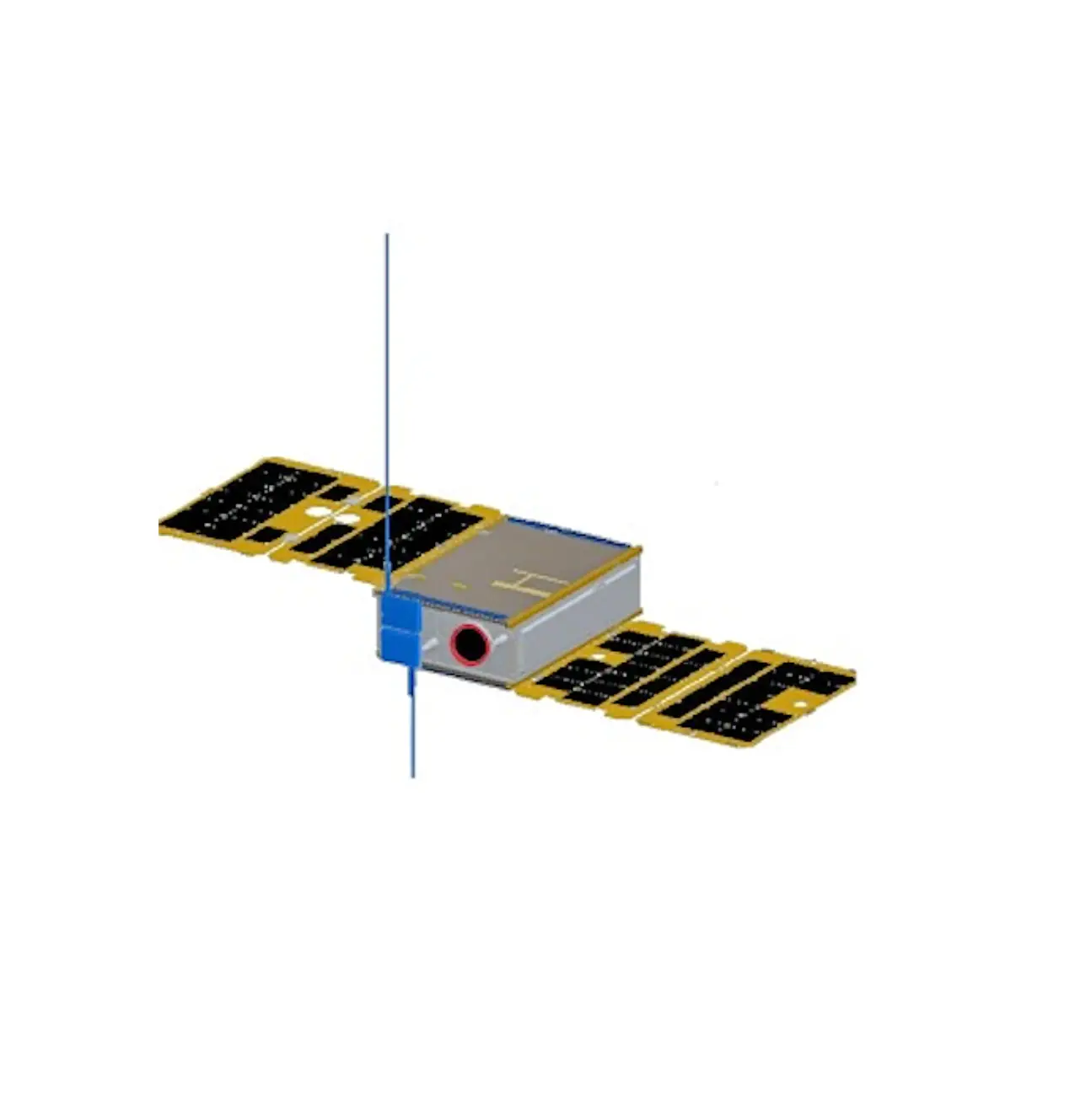
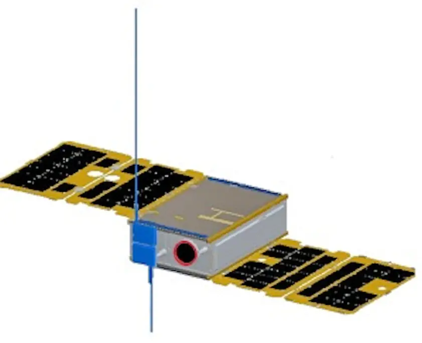
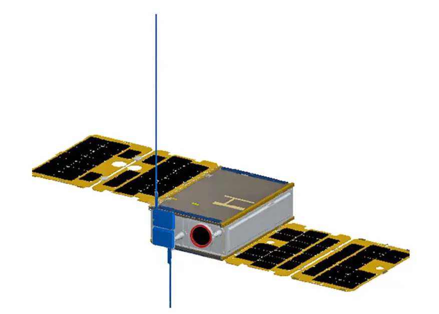
XW-3(CAS-9) satellite adopts a 6U CubeSat structure with a mass of about 10kg, an onorbit envelope size of 340.5×121.76x998mm with four solar array panels and a threeaxis stabilized attitude control system is used, long term power consumption is about
Technical specifications
- VHF antenna: 1/4 wavelength whip antenna
- UHF antenna: 1/4 wavelength whip antenna
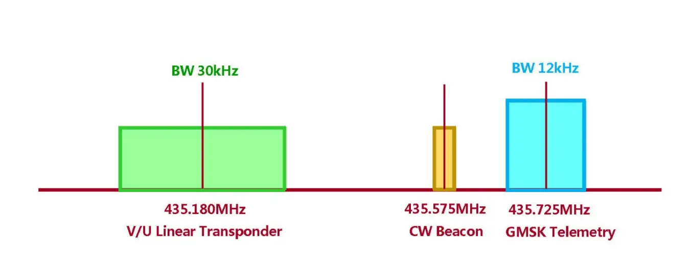
- CW telemetry beacon:
- Frequency: 435.575MHz
- RF power: 20dBm
- CW rate: 22wpm
- GMSK telemetry:
- Frequency: 435.725MHz
- RF power: 23dBm
- Data rate: 4800bps
- V/U mode linear transponder:
- Uplink frequency: 145.870MHz
- Downlink frequency: 435.180MHz
- RF power: 20dBm
- Bandwidth: 30kHz
- Spectrum inverted
- Photo download remote control:
- Subsequently public
CW Telemetry Beacon
CW beacon sending sequence
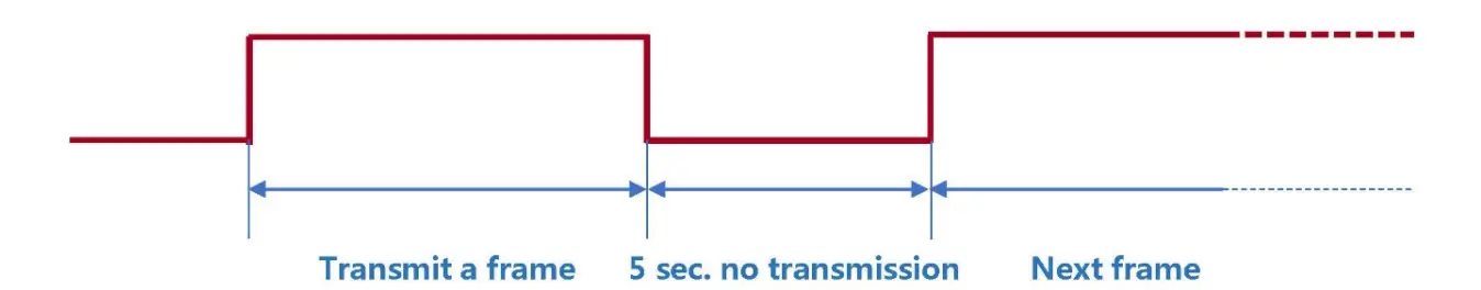
- Send stop interval time: 5s
- CW sending rate: 22wpm
CW beacon frame format
| Sending order | Sending content | Description | Remarks |
| 1 | CAS9 | Satellite ID | Send in standard Morse code |
| 2 | DFH | Telemetry information start identifier | |
| 3 | DFH | Telemetry information start identifier | |
| 4 | CH1~ CH30 | Telemetry channel 1~Telemetry channel 30 | Send this channel information, see [Digital Code Table] below |
| 5 | CAMSAT | Telemetry information end flag | Send in standard Morse code |
| 6 | CAMSAT | Telemetry information end flag |
The telemetry data (CH1 to CH30) are coded as follows:
Digital Code Table
| Digital | Code |
| 0 | T |
| 1 | A |
| 2 | U |
| 3 | V |
| 4 | 4 |
| 5 | E |
| 6 | 6 |
| 7 | B |
| 8 | D |
| 9 | N |
CW beacon telemetry information and data analysis
| Channel | Parameter name | Type | Value range | Parsing algorithm | Unit | |
| Mini. | Max. | |||||
| CH1 | CW telemetry frame transmission counter | data | 000 | 999 | Every time a frame is sent, the CW telemetry frame counter is incremented by 1, and starts counting from 000 when it is full | Time |
| CH2 | Remote control command receiving counter | data | 000 | 999 | Every time a remote control command is received, the counter is incremented by 1, and start counting from 000 when it is full | Time |
| CH3 | IHU reset counter | data | 000 | 999 | Every time IHU is reset, the counter is incremented by 1, and start counting from 000 when it is full | Time |
| CH4 | Device switch status | state | 000 | 711 | XYZ X: 0- Linear transponder is off, In-orbit mode, test mode disabled
Y: 0- telemetry data in model 0; 1- telemetry data in mode 1 | – |
| CH5 | Device switch status | state | 000 | 111 | XYZ X: 0- with OBDH data; 1- without OBDH data Y: Photo download enable (0- disable /1- enable | – |
| Channel | Parameter name | Type | Value range | Parsing algorithm | Unit | |
| Mini. | Max. | |||||
| Z: GMSK Telemetry RF power (0- low power /- 1 high power) | ||||||
| CH6 | 12V power supply voltage | data | 000 | 999 | V=N/10 | V |
| CH7 | VU 12V current | data | 000 | 999 | I=N | mA |
| CH8 | VU 5V voltage | data | 000 | 999 | V=N/100 | V |
| CH9 | VU 3.8V voltage | data | 000 | 999 | I=N/100 | V |
| CH10 | VU 3.3V voltage 1 | data | 000 | 999 | V=N/100 | V |
| CH11 | VU 3.3V voltage 2 | data | 000 | 999 | V=N/100 | V |
| CH12 | VU 3.8V current | data | 000 | 999 | I=N | mA |
| CH13 | Transmitter 3.8V current | data | 000 | 999 | I=N | mA |
| CH14 | Receiver 3.8V current | data | 000 | 999 | I=N | mA |
| CH15 | AGC voltage | data | 000 | 999 | V=N/100 | V |
| CH16 | RF transmit power | data | 000 | 999 | W=N | mW |
| CH17 | RF reflected power | data | 000 | 999 | W=N | mW |
| CH18 | Thermoelectric power generation voltage 1 | data | 000 | 999 | V=N/100 | V |
| CH19 | Thermoelectric power generation voltage 2 | data | 000 | 999 | V=N/100 | V |
| CH20 | UHF Transmitter PA temperature | data | 000 | 999 | XYZ | ℃ |
| Channel | Parameter name | Type | Value range | Parsing algorithm | Unit | |
| Mini. | Max. | |||||
| CH21 | VHF Receiver temperature | data | 000 | 999 | When X is 0-2, it represents a positive temperature; X is 3-4, it represents a negative temperature. For example: 000 : 0℃ 025 : 25℃ 125 : 125℃ 301 : -1℃ 311 : -11℃ 391 : -91℃ 421 : -121℃ | ℃ |
| CH22 | IHU temperature | data | 000 | 999 | ℃ | |
| CH23 | Thermoelectric generator temperature 1 | data | 000 | 999 | ℃ | |
| CH24 | Thermoelectric generator temperature 2 | data | 000 | 999 | ℃ | |
| CH25 | Satellite primary bus voltage | data | 000 | 999 | V=N/10 | V |
| CH26 | Satellite load total current | data | 000 | 999 | I=N/100 | A |
| CH27 | Solar array current | data | 000 | 999 | I=N/100 | A |
| CH28 | Battery charging current | data | 000 | 999 | I=N/100 | A |
| CH29 | Battery discharge current | data | 000 | 999 | I=N/100 | A |
| CH30 | +5.3V supply voltage | data | 000 | 999 | V=N/100 | V |
GMSK telemetry data
GMSK telemetry frame format and communication protocol
XW-3(CAS-9) satellite GMSK telemetry data is sent in the AX.25 UI frame format. The user data of each frame is 126 bytes, and
the allocation is as follows:
| Function code | Telemetry data content |
| 7Byte | 119Byte |
| W0~W6:0x0100010001007E | W7~W125 |
GMSK telemetry data format and analysis method
| Sending order | Starting position | Data length | Telemetry data function description | Telemetry data parsing algorithm |
| 1 | W7 | 6Byte | Satellite time | W1-Year: 00~99, representing 2000~2099 W2-Month: 01~12, representing January to December W3-Day: 01~31, representing 1st~31st W4-Hour: 00~23, representing 0:00~23:00 W5-minute: 00~59, representing 0 minutes~59 minutes W6-second: 00~59, representing 0 seconds~59 seconds |
| 2 | W13 | 6Byte | 48 hours reset time | W1-Year: 00~99, representing 2000~2099 |
| Sending order | Starting position | Data length | Telemetry data function description | Telemetry data parsing algorithm |
| W2-Month: 01~12, representing January to December W3-Day: 01~31, representing 1st~31st W4-Hour: 00~23, representing 0:00~23:00 W5-minute: 00~59, representing 0 minutes~59 minutes W6-second: 00~59, representing 0 seconds~59 seconds | ||||
| 3 | W19 | 1Byte | Total reset counter | W1 is an integer. Restart counting from 0 after counting up Range: 0~255 |
| 4 | W20 | 1Byte | Telemetry Frame Transmission Counter | W1 is an integer. Restart counting from 0 after counting up Range: 0~255 |
| 5 | W21 | 1Byte | Remote control frame reception counter | W1 is an integer. Restart counting from 0 after counting up Range: 0~255 |
| 6 | W22 | 1Byte | Remote control command execution counter | W1 is an integer. Restart counting from 0 after counting up Range: 0~255 |
| 7 | W23 | 1Byte | Remote control command forwarding counter | W1 is an integer. Restart counting from 0 after counting up Range: 0~255 |
| 8 | W24 | 1Byte | Watchdog switch status | b7b6b5b4: reserved b3: VU CPU I/O acquisition watchdog (0 off/1 on) b2: ADC software watchdog (0 off/1 on) b1: Temperature measurement software watchdog (0 off/1 on) b0: Remote control software watchdog (0 off/1 on) |
| 9 | W25 | 1Byte | CPU I/O acquisition watchdog reset counter | W1 is an integer. Restart counting from 0 after counting up Range: 0~255 |
| 10 | W26 | 1Byte | ADC software watchdog reset counter | W1 is an integer. Restart counting from 0 after counting up |
| Sending order | Starting position | Data length | Telemetry data function description | Telemetry data parsing algorithm |
| Range: 0~255 | ||||
| 11 | W27 | 1Byte | Temperature measurement software watchdog reset counter | W1 is an integer. Restart counting from 0 after counting up Range: 0~255 |
| 12 | W28 | 1Byte | Remote control software watchdog reset counter | W1 is an integer. Restart counting from 0 after counting up Range: 0~255 |
| 13 | W29 | 1Byte | Working status 1 | b7: Allow to set to track mode (0 disable/1 enable) b6: Photo download enable (0 disable/1 enable) b5: Delayed telemetry switch status (0 off/1 on) b4: Test mode enable (0 disable/1 enable) b3: 0: Linear transponder off; 1: Linear transponder on. b2: OBDH time calibration enable (0 disable/1 enable) b1: Telemetry transmit RF power(0 low power/1 high power) b0: Program control mode enable (0-disable/1 enable) |
| 14 | W30 | 1Byte | Working status 2 | b7: In-orbit mode (0 not In-orbit/1 In-orbit) b6: Battery discharge switch is on (0 off/1 on) b5: Program control mode switch enable (0 disable/1 enable) b4: OBDH B on A off power distribution switch status (0 off/1 on) b3: OBDH A on B off power distribution switch status (0 off/1 on) b2: VHF antenna deployed state (0 not deployed/1 deployed) b1: UHF antenna expanded state (0 not expanded/1 expanded) b0: the status of the total antenna deployment switch (0 off/1 on) |
| 15 | W31 | 1Byte | Working status 3 | b7: Waiting for into orbit mode (0 not/1 waiting) |
| Sending order | Starting position | Data length | Telemetry data function description | Telemetry data parsing algorithm |
| b6: On–Track mode (0 non/1 On-track) b5: OBDH SPI state (0 normal/1 failure) b4: ADC I2C state (0 normal/1 failure) b3: Temperature measurement I2C state (0 normal/1 failure) b2: Clock I2C state (0 normal/1 failure) b1: Inertial navigator serial port state (0 normal/1 failure) b0: Flash SPI state (0 normal/1 failure) | ||||
| 16 | W32 | 2Byte | 12V power supply voltage | W1 is the integer part, W2 is the decimal part (1 decimal place) Range: 0~15.0(V) |
| 17 | W34 | 2Byte | VU 12V power supply current | W1W2 is an integer Range: 0~1500(mA) |
| 18 | W36 | 2Byte | VU 5V power supply voltage | W1 is the integer part, W2 is the decimal part (2 decimal places) Range: 0~10.00(V) |
| 19 | W38 | 2Byte | VU 3.8V power supply voltage | W1 is the integer part, W2 is the decimal part (2 decimal places) Range: 0~5.00(V) |
| 20 | W40 | 2Byte | IHU 3.3V voltage 1 | W1 is the integer part, W2 is the decimal part (2 decimal places) Range: 0V~5.00(V) |
| 21 | W42 | 2Byte | IHU 3.3V voltage 2 | W1 is the integer part, W2 is the decimal part (2 decimal places) Range: 0V~5.00(V) |
| 22 | W44 | 2Byte | IHU 3.8V current | W1W2 is an integer Range: 0~500(mA) |
| 23 | W46 | 2Byte | UHF transmitter 3.8V current | W1W2 is an integer Range: 0~500(mA) |
| Sending order | Starting position | Data length | Telemetry data function description | Telemetry data parsing algorithm |
| 24 | W48 | 2Byte | VHF receiver 3.8V current | W1W2 is an integer Range: 0~500(mA) |
| 25 | W50 | 2Byte | VHF AGC voltage | W1 is the integer part, W2 is the decimal part (2 decimal places) Range: 0~5.00(V) |
| 26 | W52 | 2Byte | RF transmit power | W1W2 is an integer Range: 0~2000(mW) |
| 27 | W54 | 2Byte | RF reflected power | W1W2 is an integer Range: 0~1000(mW) |
| 28 | W56 | 2Byte | Thermoelectric generator voltage 1 | W1 is the integer part, W2 is the decimal part (1 decimal place) Range: 0~30.0(V) |
| 29 | W58 | 2Byte | Thermoelectric generator voltage 2 | W1 is the integer part, W2 is the decimal part (1 decimal place) Range: 0~30.0(V) |
| 30 | W60 | 1Byte | UHF Transmitter PA temperature | B7 of W1 is the sign bit, 0 is positive, 1 is negative; b6~b0 are numerical bits Range: -100~+100(℃) |
| 31 | W61 | 1Byte | VHF Receiver temperature | B7 of W1 is the sign bit, 0 is positive, 1 is negative; b6~b0 are numerical bits Range: -100~+100(℃) |
| 32 | W62 | 1Byte | IHU temperature | B7 of W1 is the sign bit, 0 is positive, 1 is negative; b6~b0 are numerical bits Range: -100~+100(℃) |
| 33 | W63 | 1Byte | Thermoelectric generator temperature 1 | B7 of W1 is the sign bit, 0 is positive, 1 is negative; b6~b0 are numerical bits |
| Sending order | Starting position | Data length | Telemetry data function description | Telemetry data parsing algorithm |
| Range: -127~+127(℃) | ||||
| 34 | W64 | 1Byte | Thermoelectric generator temperature 2 | B7 of W1 is the sign bit, 0 is positive, 1 is negative; b6~b0 are numerical bits Range: -127~+127 (℃) |
| 35 | W65 | 3Byte | Current delay telemetry interval | W1-Hour: 00~23, representing 0:00~23:00 W2-Minute: 00~59, representing 0 minute~59 minutes W3-second: 00~59, representing 0 second~59 seconds |
| 36 | W68 | 6Byte | Delay telemetry start time setting | W1-Year: 0~99, representing 2000~2099 W2-Month: 01~12, representing January to December W3-Day: 01~31, representing 1st~31st W4-Hour: 00~23, representing 0:00~23:00 W5-minute: 00~59, representing 0 minute~59 minutes W6-second: 00~59, representing 0 second~59 seconds |
| 37 | W74 | 3Byte | Delay telemetry interval setting | W1-Hour: 00~23, representing 0:00~23:00 W2-Minute: 00~59, representing 0 minutes~59 minutes W3-second: 00~59, representing 0 seconds~59 seconds |
| 38 | W77 | 3Byte | Delay telemetry times setting | W1W2W3 is an integer Range: 0 ~ 16777215 |
| 39 | W80 | 2Byte | Attitude quaternion q0 | W1W2:Q0L Q0H q0=((Q0H<<8)|Q0L)/32768 |
| 40 | W82 | 2Byte | Attitude quaternion q1 | W1W2:Q1L Q1H q1=((Q1H<<8)|Q1L)/32768 |
| 41 | W84 | 2Byte | Attitude quaternion q2 | W1W2:Q2L Q2H |
| Sending order | Starting position | Data length | Telemetry data function description | Telemetry data parsing algorithm | |
| q2=((Q2H<<8)|Q2L)/32768 | |||||
| 42 | W86 | 2Byte | Attitude quaternion q3 | W1W2:Q3L Q3H q3=((Q3H<<8)|Q3L)/32768 | |
| 43 | W88 | 2Byte | X-axis angular speed | W1W2:WxL WxH Wx=((WxH<<8)|WxL)/32768*2000(°/s) | |
| 44 | W90 | 2Byte | Y axis angular speed | W1W2:WyL WyH Wy=((WyH<<8)|WyL)/32768*2000(°/s) | |
| 45 | W92 | 2Byte | Z-axis angular speed | W1W2:WzL WzH Wz=((WzH<<8)|WzL)/32768*2000(°/s) | |
| 46 | W94 | 4Byte | Satellite time seconds | W1 second highest byte | The four bytes are the accumulated value of the whole second of UTC since 0:00:00:00 UTC on January 1, 2009 (0:00 after the jumped second). |
| W2 second high byte | |||||
| W3 second low byte | |||||
| W4 second lowest byte | |||||
| 47 | W98 | 2Byte | Satellite time milliseconds | W1W2 is an integer | |
| 48 | W100 | 2Byte | Satellite primary bus voltage | W1 is the integer part, W2 is the decimal part (1 decimal place) Range: 0~30.0(V) | |
| 49 | W102 | 2Byte | Satellite load total current | W1 is the integer part, W2 is the decimal part (1 decimal place) Range: 0~10.0(A) | |
| 50 | W104 | 2Byte | Solar array current | W1 is the integer part, W2 is the decimal part (1 decimal place) Range: 0~10.0(A) | |
| 51 | W106 | 2Byte | Battery charging current | W1 is the integer part, W2 is the decimal part (1 decimal place) | |
| Sending order | Starting position | Data length | Telemetry data function description | Telemetry data parsing algorithm |
| Range: 0~ -10.0(A) | ||||
| 52 | W108 | 2Byte | Battery discharge current | W1 is the integer part, W2 is the decimal part (1 decimal place) Range: 0~10.0(A) |
| 53 | W110 | 2Byte | +5.3V supply voltag | W1 is the integer part, W2 is the decimal part (1 decimal place) Range: 0~30.0(V) |
| 54 | W112 | 1Byte | Satellite attitude control mode | b7~b0 (the following are hexadecimal representations, where b7~b4 correspond to the main operating mode, and b3~b0 correspond to the sub-mode): 0x00–Active segment mode 0x11—Full attitude capture mode: Rate damping 0x12—Full attitude capture mode: Sun search 0x13—Full attitude capture mode: Orientation to sun 0x14—Full attitude capture mode: Orientation to the ground 0x15—Full attitude capture mode: Maneuvering to the sun 0x20—Attitude maneuver mode 0x23—Attitude maneuver mode: Switch to cruise to the sun 0x24—Attitude maneuver mode: Switch to normal operation 0x25—Attitude maneuver mode: Switch to offset flight 0x26—Attitude maneuver mode: Switch to a fixed point to stare 0x27—Attitude maneuver mode: Switch to inertial space pointing 0x30—Cruising mode to the sun 0x40—Normal operating mode 0x50-Biased flight mode |
| Sending order | Starting position | Data length | Telemetry data function description | Telemetry data parsing algorithm |
| 0x60—Fixed-point staring mode 0x70—Inertial space pointing mode 0xB0—Track control mode 0xC0—Stop control mode 0xD0-Reset mode Other: Invalid mode | ||||
| 55 | W113 | 1Byte | Satellite longitude | B7 of W1 is a character bit, 0 is positive, 1 is negative; b6~b0 are numeric bits Range: N*2, (-180 º ~180 º) |
| 56 | W111 | 1Byte | Satellite latitude | B7 of W1 is a character bit, 0 is positive, 1 is negative; b6~b0 are numeric bits Range: N*2, (-90 º ~90 º) |
| 57 | W111 | 1Byte | Rolling angle estimation | B7 of W1 is a character bit, 0 is positive, 1 is negative; b6~b0 are numeric bits Range: -125~+125 º |
| 58 | W116 | 1Byte | Pitch angle estimation | B7 of W1 is a character bit, 0 is positive, 1 is negative; b6~b0 are numeric bits Range: -125~+125 º |
| 59 | W111 | 1Byte | Yaw angle estimation | B7 of W1 is a character bit, 0 is positive, 1 is negative; b6~b0 are numeric bits Range: -125~+125 º |
| 60 | W118 | 2Byte | Uplink remote control data block counter | W1 is the high byte, W2 is the low byte Range: 0~65535 |
| Sending order | Starting position | Data length | Telemetry data function description | Telemetry data parsing algorithm |
| 61 | W120 | 1Byte | X-band transceiver working status | b7: X-band transceiver transmitter switch status 1: On; 0: Off b6: X-band transceiver position synchronization lock indication 1: locked; 0: lost lock b5: X-band transceiver remote control carrier lock indication 1: locked; 0: lost lock b4: X-band transceiver remote control pseudo code lock indication 1: locked; 0: lost lock b3: CRC check status of X-band transceiver remote control data 1: CRC is correct; 0: CRC is wrong b2: X-band transceiver remote control channel status self-check 1: valid; 0: invalid b1b0: X-band transceiver remote control code group status 01: Code group 1; 10: Code group 2 |
| 62 | W121 | 2Byte | X-band transceiver AGC voltage | W1 is the integer part, W2 is the decimal part (1 decimal place) Range: 0~6.6(V) |
| 63 | W123 | 2Byte | X-band transceiver transmit power level | W1 is the integer part, W2 is the decimal part (1 decimal place) Range: 0~6.6(V) |
| 64 | W125 | 1Byte | X-band transceiver SPI interface status | b7~b4: X-band transceiver baseband execution counter 0 ~15 b3b2: X-band transceiver SPI interface empty flag 01: valid; 10: invalid b1: X-band transceiver SPI-MISO data with or without monitoring 1: with data; 0: without data b0: X-band transceiver SPI-MOSI data with or without monitoring 1: with data; 0: without data |
Space camera photo data
XW-3 (CAS-9) satellite can store up to 10 photos taken by the space camera. The newly taken photo data will overwrite the old photo data, first in, first out. There are two photo resolutions, one is 256×256 pixels, and the data size of each photo is 64k bytes; the other is 512×512 pixels, and the data size of each photo is 256k bytes. Users can download the photo storage information to learn about the photos stored on the satellite, and select the photos to download.
Photo storage information
XW-3 (CAS-9) satellite photo storage information is stored in the solid-state memory on the satellite in the following format.
| Function code | Photo storage information content |
| 7Byte | 80Byte |
| W0~W6:0x02000100010057 | W7~W86 |
| Photo storage information content | |||
| Article 1 Photo storage information | Article 2 Photo storage information | …… | Article 10 Photo storage information |
| 8Byte | 8Byte | …… | 8Byte |
The format of each photo storage information is shown in the following table:
| 1Byte | 1Byte | 1Byte | 1Byte | 1Byte | 1Byte | 1Byte | 1Byte | |
| Year | Month | Day | Hour | Minute | Second | bit7~Bit3 | Bit2~Bit0 | 1Byte |
| Photograph time | Camera number | Photo counter | ||||||
Photo information
Including photo time, camera number and photo counter. For detailed description,
please refer to this article (instructions related to photo storage information).
Photo data
Fill the data of a certain photo, except for the last frame, the photo data of each photo frame is 240 bytes, and the photo data of the last frame is the actual number of remaining bytes. The total number of frames in the photo frame is the total number of frames of all the photo data, and the frame number is the frame number of the photo data in all the photo data.
W15 photo specifications
| Photo specifications | Width (pixels) | High (pixels) | Note |
| 1 | — | — | Reserve |
| 2 | — | — | Reserve |
| 3 | 256 | 256 | 64K bytes |
| 4 | 512 | 512 | 256K bytes |
| 5 | — | — | Reserve |
After downloading the photo data frame, the 240 bytes of “photo data” (the last frame is less than 240 bytes) in the above description of each frame of data are combined in a file in order, the file is saved with the raw extension, and then you can Use the photo browsing tool that can open raw format pictures to view the photos.
Photo data download remote command
Subsequently public.
amateur Radio Satellite User Manual")


