XW-4(CAS-10)Amateur Radio Satellite
XW-4 (CAS-10) Amateur Radio Satellite
User’s Manual
Ver. 1.0


Alan Kung, BA1DU
2022-12-16
![]() XW-4(CAS-10)Amateur Radio Satellite User’s Manual
XW-4(CAS-10)Amateur Radio Satellite User’s Manual
XW-4(CAS-10)Amateur Radio Satellite User’s Manual V1.0 2022-12-16
Alan Kung,BA1DU
The CAMSAT XW-4 (CAS-10) satellite was launched into the Chinese Space Station on November 12, 2022 aboard China’s Tianzhou-5 cargo spacecraft, and was launched by the Long March-7 Y6 launch vehicle from the Wenchang Launch Center in Hainan, China. It is currently planned that the XW-4 (CAS-10) satellite will be separated from the Chinese space station and enter operational orbit at 01:30 UTC on December 18, 2022. The functions of XW-4 (CAS-10) satellite include UHF CW telemetry beacon, GMSK telemetry data transmission, V/U mode linear transponder, a visible light band space camera.

China Space Station
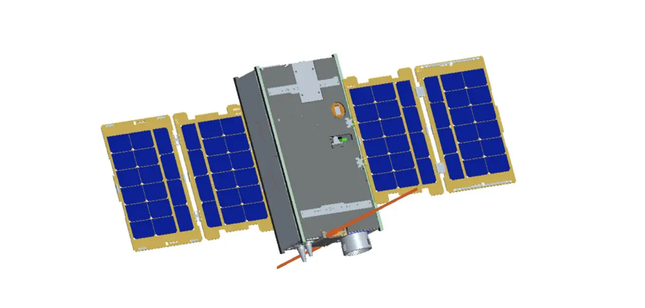
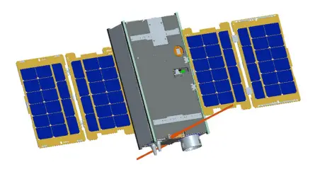
 XW-4 (CAS-10) satellite
The TLE at the separation point is the same as the China Space Station:
1 / 27 V1.0 by BA1DU
![]() XW-4(CAS-10)Amateur Radio Satellite User’s Manual
XW-4(CAS-10)Amateur Radio Satellite User’s Manual
XW-4 (CAS-10)
1 48274U 21035A 22349.57666509 .00020514 00000+0 25201-3 0 9994 2 48274 41.4739 194.5783 0004074 111.0935 347.0781 15.59787538 93120
After the satellite completes the in-orbit test and works normally, the space camera photo download will be open to amateur radio enthusiasts all over the world. When the relevant remote control command is received by the satellite, the GMSK telemetry channel will be used to downlink the photo storage information and photo data, and the telemetry data will stop sending at that time.
XW-4(CAS-10) satellite adopts a 8U CubeSat structure with a mass of about 12kg, an on-orbit envelope size of 1007x790x475mm with four solar array panels and a three axis stabilized attitude control system is used, long-term power consumption is about 18.3 Watts.
 2 / 27 V1.0 by BA1DU
![]() XW-4(CAS-10)Amateur Radio Satellite User’s Manual
XW-4(CAS-10)Amateur Radio Satellite User’s Manual
1. Technical specifications:
- VHF antenna: 1/4 wavelength whip antenna
- UHF antenna: 1/4 wavelength whip antenna
- CW telemetry beacon:
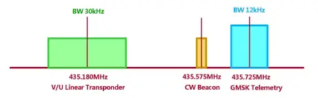
● Frequency: 435.575MHz
● RF power: 20dBm
● CW rate: 22wpm - GMSK telemetry:
●Frequency: 435.725MHz ●RF power: 23dBm ●Data rate: 4800bps - V/U mode linear transponder: ●Uplink frequency: 145.870MHz ●Downlink frequency: 435.180MHz ●RF power: 20dBm ●Bandwidth: 30kHz ●Spectrum inverted
- Photo download remote control: ●Coming soon…
2. CW Telemetry Beacon:
(1) CW beacon sending sequence
3 / 27 V1.0 by BA1DU
![]() XW-4(CAS-10)Amateur Radio Satellite User’s Manual
XW-4(CAS-10)Amateur Radio Satellite User’s Manual 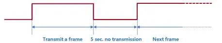
- Send stop interval time: 5s
- CW sending rate: 22wpm
(2)CW beacon frame format
Sending order | Sending content | Description | Remarks |
1 | CAS10 | Satellite ID | Send in standard Morse code |
2 | DFH | Telemetry information start identifier | |
3 | DFH | Telemetry information start identifier | |
4 | CH1~ CH30 | Telemetry channel 1~Telemetry channel 30 | Send this channel information, see [Digital Code Table] below |
5 | CAMSAT | Telemetry information end flag | Send in standard Morse code |
6 | CAMSAT | Telemetry information end flag |
The telemetry data (CH1 to CH30) are coded as follows:
Digital Code Table
Digital | Code |
0 | T |
1 | A |
2 | U |
3 | V |
4 | 4 |
5 | E |
4 / 27 V1.0 by BA1DU
![]() XW-4(CAS-10)Amateur Radio Satellite User’s Manual
XW-4(CAS-10)Amateur Radio Satellite User’s Manual
6 | 6 |
7 | B |
8 | D |
9 | N |
5 / 27 V1.0 by BA1DU
![]() XW-4(CAS-10)Amateur Radio Satellite User’s Manual
XW-4(CAS-10)Amateur Radio Satellite User’s Manual
(3)CW beacon telemetry information and data analysis
Channel | Parameter name | Type | Value range | Parsing algorithm | Unit | |
Mini. | Max. | |||||
CH1 | CW telemetry frame transmission counter | data | 000 | 999 | Every time a frame is sent, the CW telemetry frame counter is incremented by 1, and starts counting from 000 when it is full | Time |
CH2 | Remote control command receiving counter | data | 000 | 999 | Every time a remote control command is received, the counter is incremented by 1, and start counting from 000 when it is full | Time |
CH3 | IHU reset counter | data | 000 | 999 | Every time IHU is reset, the counter is incremented by 1, and start counting from 000 when it is full | Time |
CH4 | Device switch status | state | 000 | 711 | XYZ X: 0- Linear transponder is off, In-orbit mode, test mode disabled 1- Linear transponder is on, In-orbit mode, test mode disabled 2- Linear transponder is off, On-track mode, test mode is disabled 3- Linear transponder is on, On-track mode, test mode is disabled 4- Linear transponder is off, In-orbit mode, test mode enabled 5- Linear transponder is on, In-orbit mode, test mode enabled 6- Linear transponder is off, On-track mode, test mode is enabled 7- Linear transponder is on, On-track mode, test mode is enabled Y: 0- telemetry data in model 0; 1- telemetry data in mode 1 Z: 0- OBDH time calibration disabled; 1- OBDH time calibration enabled | – |
CH5 | Device switch status | state | 000 | 111 | XYZ X: 0- with OBDH data; 1- without OBDH data Y: Photo download enable (0- disable /1- enable) | – |
6 / 27 V1.0 by BA1DU
![]() XW-4(CAS-10)Amateur Radio Satellite User’s Manual
XW-4(CAS-10)Amateur Radio Satellite User’s Manual
Channel | Parameter name | Type | Value range | Parsing algorithm | Unit | |
Mini. | Max. | |||||
Z: GMSK Telemetry RF power (0- low power /- 1 high power) | ||||||
CH6 | 12V power supply voltage | data | 000 | 999 | V=N/10 | V |
CH7 | VU 12V current | data | 000 | 999 | I=N | mA |
CH8 | VU 5V voltage | data | 000 | 999 | V=N/100 | V |
CH9 | VU 3.8V voltage | data | 000 | 999 | I=N/100 | V |
CH10 | VU 3.3V voltage 1 | data | 000 | 999 | V=N/100 | V |
CH11 | VU 3.3V voltage 2 | data | 000 | 999 | V=N/100 | V |
CH12 | VU 3.8V current | data | 000 | 999 | I=N | mA |
CH13 | Transmitter 3.8V current | data | 000 | 999 | I=N | mA |
CH14 | Receiver 3.8V current | data | 000 | 999 | I=N | mA |
CH15 | AGC voltage | data | 000 | 999 | V=N/100 | V |
CH16 | RF transmit power | data | 000 | 999 | W=N | mW |
CH17 | RF reflected power | data | 000 | 999 | W=N | mW |
CH18 | Reserved | data | 000 | 999 | V=N/100 | V |
CH19 | Reserved | data | 000 | 999 | V=N/100 | V |
CH20 | UHF Transmitter PA temperature | data | 000 | 999 | XYZ When X is 0-2, it represents a positive temperature; X is 3-4, it represents a negative temperature. | ℃ |
CH21 | VHF Receiver temperature | data | 000 | 999 | ℃ | |
7 / 27 V1.0 by BA1DU
![]() XW-4(CAS-10)Amateur Radio Satellite User’s Manual
XW-4(CAS-10)Amateur Radio Satellite User’s Manual
Channel | Parameter name | Type | Value range | Parsing algorithm T=N (N≤300) T=-1x (N-300) (N>300) For example: 000 : 0℃ 025 : 25℃ 125 : 125℃ 301 : -1℃ 311 : -11℃ 391 : -91℃ 421 : -121℃ | Unit | |
Mini. | Max. | |||||
CH22 | IHU temperature | data | 000 | 999 | ℃ | |
CH23 | Reserved | data | 000 | 999 | ℃ | |
CH24 | Reserved | data | 000 | 999 | ℃ | |
CH25 | Satellite primary bus voltage | data | 000 | 999 | V=N/10 | V |
CH26 | Satellite load total current | data | 000 | 999 | I=N/100 | A |
CH27 | Solar array current | data | 000 | 999 | I=N/100 | A |
CH28 | Battery charging current | data | 000 | 999 | I=N/100 | A |
CH29 | Battery discharge current | data | 000 | 999 | I=N/100 | A |
CH30 | +5.3V supply voltage | data | 000 | 999 | V=N/100 | V |
3、GMSK telemetry data:
8 / 27 V1.0 by BA1DU
XW-4(CAS-10)Amateur Radio Satellite User’s Manual
(1)GMSK telemetry frame format and communication protocol
XW-4(CAS-10) satellite GMSK telemetry data is sent in the AX.25 UI frame format. The user data of each frame is 126 bytes, and the allocation is as follows:
Function code | Telemetry data content |
7Byte | 119Byte |
W0~W6:0x0100010001007E | W7~W125 |
(2)GMSK telemetry data format and analysis method
Sending order | Starting position | Data length | Telemetry data function description | Telemetry data parsing algorithm |
1 | W7 | 6Byte | Satellite time | W1-Year: 00~99, representing 2000~2099 W2-Month: 01~12, representing January to December W3-Day: 01~31, representing 1st~31st W4-Hour: 00~23, representing 0:00~23:00 W5-minute: 00~59, representing 0 minutes~59 minutes W6-second: 00~59, representing 0 seconds~59 seconds |
2 | W13 | 6Byte | 48 hours reset time | W1-Year: 00~99, representing 2000~2099 W2-Month: 01~12, representing January to December W3-Day: 01~31, representing 1st~31st |
9 / 27 V1.0 by BA1DU
XW-4(CAS-10)Amateur Radio Satellite User’s Manual
Sending order | Starting position | Data length | Telemetry data function description | Telemetry data parsing algorithm |
W4-Hour: 00~23, representing 0:00~23:00 W5-minute: 00~59, representing 0 minutes~59 minutes W6-second: 00~59, representing 0 seconds~59 seconds | ||||
3 | W19 | 1Byte | Total reset counter | W1 is an integer. Restart counting from 0 after counting up Range: 0~255 |
4 | W20 | 1Byte | Telemetry Frame Transmission Counter | W1 is an integer. Restart counting from 0 after counting up Range: 0~255 |
5 | W21 | 1Byte | Remote control frame reception counter | W1 is an integer. Restart counting from 0 after counting up Range: 0~255 |
6 | W22 | 1Byte | Remote control command execution counter | W1 is an integer. Restart counting from 0 after counting up Range: 0~255 |
7 | W23 | 1Byte | Remote control command forwarding counter | W1 is an integer. Restart counting from 0 after counting up Range: 0~255 |
8 | W24 | 1Byte | Watchdog switch status | b7b6b5b4: reserved b3: VU CPU I/O acquisition watchdog (0 off/1 on) b2: ADC software watchdog (0 off/1 on) b1: Temperature measurement software watchdog (0 off/1 on) b0: Remote control software watchdog (0 off/1 on) |
9 | W25 | 1Byte | CPU I/O acquisition watchdog reset counter | W1 is an integer. Restart counting from 0 after counting up Range: 0~255 |
10 | W26 | 1Byte | ADC software watchdog reset counter | W1 is an integer. Restart counting from 0 after counting up Range: 0~255 |
11 | W27 | 1Byte | Temperature measurement software watchdog | W1 is an integer. Restart counting from 0 after counting up |
10 / 27 V1.0 by BA1DU
XW-4(CAS-10)Amateur Radio Satellite User’s Manual
Sending order | Starting position | Data length | Telemetry data function description | Telemetry data parsing algorithm |
reset counter | Range: 0~255 | |||
12 | W28 | 1Byte | Remote control software watchdog reset counter | W1 is an integer. Restart counting from 0 after counting up Range: 0~255 |
13 | W29 | 1Byte | Working status 1 | b7: Allow to set to track mode (0 disable/1 enable) b6: Photo download enable (0 disable/1 enable) b5: Delayed telemetry switch status (0 off/1 on) b4: Test mode enable (0 disable/1 enable) b3: 0: Linear transponder off; 1: Linear transponder on. b2: OBDH time calibration enable (0 disable/1 enable) b1: Telemetry transmit RF power(0 low power/1 high power) b0: Program control mode enable (0-disable/1 enable) |
14 | W30 | 1Byte | Working status 2 | b7: In-orbit mode (0 not In-orbit/1 In-orbit) b6: Battery discharge switch is on (0 off/1 on) b5: Program control mode switch enable (0 disable/1 enable) b4: OBDH B on A off power distribution switch status (0 off/1 on) b3: OBDH A on B off power distribution switch status (0 off/1 on) b2: VHF antenna deployed state (0 not deployed/1 deployed) b1: UHF antenna expanded state (0 not expanded/1 expanded) b0: the status of the total antenna deployment switch (0 off/1 on) |
15 | W31 | 1Byte | Working status 3 | b7: Waiting for into orbit mode (0 not/1 waiting) b6: On–Track mode (0 non/1 On-track) b5: OBDH SPI state (0 normal/1 failure) b4: ADC I2C state (0 normal/1 failure) |
11 / 27 V1.0 by BA1DU
XW-4(CAS-10)Amateur Radio Satellite User’s Manual
Sending order | Starting position | Data length | Telemetry data function description | Telemetry data parsing algorithm |
b3: Temperature measurement I2C state (0 normal/1 failure) b2: Clock I2C state (0 normal/1 failure) b1: Inertial navigator serial port state (0 normal/1 failure) b0: Flash SPI state (0 normal/1 failure) | ||||
16 | W32 | 2Byte | 12V power supply voltage | W1 is the integer part, W2 is the decimal part (1 decimal place) Range: 0~15.0(V) |
17 | W34 | 2Byte | VU 12V power supply current | W1W2 is an integer Range: 0~1500(mA) |
18 | W36 | 2Byte | VU 5V power supply voltage | W1 is the integer part, W2 is the decimal part (2 decimal places) Range: 0~10.00(V) |
19 | W38 | 2Byte | VU 3.8V power supply voltage | W1 is the integer part, W2 is the decimal part (2 decimal places) Range: 0~5.00(V) |
20 | W40 | 2Byte | IHU 3.3V voltage 1 | W1 is the integer part, W2 is the decimal part (2 decimal places) Range: 0V~5.00(V) |
21 | W42 | 2Byte | IHU 3.3V voltage 2 | W1 is the integer part, W2 is the decimal part (2 decimal places) Range: 0V~5.00(V) |
22 | W44 | 2Byte | IHU 3.8V current | W1W2 is an integer Range: 0~500(mA) |
23 | W46 | 2Byte | UHF transmitter 3.8V current | W1W2 is an integer Range: 0~500(mA) |
24 | W48 | 2Byte | VHF receiver 3.8V current | W1W2 is an integer Range: 0~500(mA) |
25 | W50 | 2Byte | VHF AGC voltage | W1 is the integer part, W2 is the decimal part (2 decimal places) |
12 / 27 V1.0 by BA1DU
XW-4(CAS-10)Amateur Radio Satellite User’s Manual
Sending order | Starting position | Data length | Telemetry data function description | Telemetry data parsing algorithm |
Range: 0~5.00(V) | ||||
26 | W52 | 2Byte | RF transmit power | W1W2 is an integer Range: 0~2000(mW) |
27 | W54 | 2Byte | RF reflected power | W1W2 is an integer Range: 0~1000(mW) |
28 | W56 | 2Byte | Reserved | W1 is the integer part, W2 is the decimal part (1 decimal place) Range: 0~30.0(V) |
29 | W58 | 2Byte | Reserved | W1 is the integer part, W2 is the decimal part (1 decimal place) Range: 0~30.0(V) |
30 | W60 | 1Byte | UHF Transmitter PA temperature | B7 of W1 is the sign bit, 0 is positive, 1 is negative; b6~b0 are numerical bits Range: -100~+100(℃) |
31 | W61 | 1Byte | VHF Receiver temperature | B7 of W1 is the sign bit, 0 is positive, 1 is negative; b6~b0 are numerical bits Range: -100~+100(℃) |
32 | W62 | 1Byte | IHU temperature | B7 of W1 is the sign bit, 0 is positive, 1 is negative; b6~b0 are numerical bits Range: -100~+100(℃) |
33 | W63 | 1Byte | Reserved | B7 of W1 is the sign bit, 0 is positive, 1 is negative; b6~b0 are numerical bits Range: -127~+127(℃) |
34 | W64 | 1Byte | Reserved | B7 of W1 is the sign bit, 0 is positive, 1 is negative; b6~b0 are numerical bits |
13 / 27 V1.0 by BA1DU
XW-4(CAS-10)Amateur Radio Satellite User’s Manual
Sending order | Starting position | Data length | Telemetry data function description | Telemetry data parsing algorithm |
Range: -127~+127 (℃) | ||||
35 | W65 | 3Byte | Current delayed telemetry interval | W1-Hour: 00~23, representing 0:00~23:00 W2-Minute: 00~59, representing 0 minute~59 minutes W3-second: 00~59, representing 0 second~59 seconds |
36 | W68 | 6Byte | Delay telemetry start time setting | W1-Year: 0~99, representing 2000~2099 W2-Month: 01~12, representing January to December W3-Day: 01~31, representing 1st~31st W4-Hour: 00~23, representing 0:00~23:00 W5-minute: 00~59, representing 0 minute~59 minutes W6-second: 00~59, representing 0 second~59 seconds |
37 | W74 | 3Byte | Delayed telemetry interval setting | W1-Hour: 00~23, representing 0:00~23:00 W2-Minute: 00~59, representing 0 minutes~59 minutes W3-second: 00~59, representing 0 seconds~59 seconds |
38 | W77 | 3Byte | Delayed telemetry times setting | W1W2W3 is an integer Range: 0 ~ 16777215 |
39 | W80 | 2Byte | Attitude quaternion q0 | W1W2:Q0L Q0H q0=((Q0H<<8)|Q0L)/32768 |
40 | W82 | 2Byte | Attitude quaternion q1 | W1W2:Q1L Q1H q1=((Q1H<<8)|Q1L)/32768 |
41 | W84 | 2Byte | Attitude quaternion q2 | W1W2:Q2L Q2H q2=((Q2H<<8)|Q2L)/32768 |
42 | W86 | 2Byte | Attitude quaternion q3 | W1W2:Q3L Q3H q3=((Q3H<<8)|Q3L)/32768 |
14 / 27 V1.0 by BA1DU
XW-4(CAS-10)Amateur Radio Satellite User’s Manual
Sending order | Starting position | Data length | Telemetry data function description | Telemetry data parsing algorithm | |
43 | W88 | 2Byte | X-axis angular speed | W1W2:WxL WxH Wx=((WxH<<8)|WxL)/32768*2000(°/s) | |
44 | W90 | 2Byte | Y axis angular speed | W1W2:WyL WyH Wy=((WyH<<8)|WyL)/32768*2000(°/s) | |
45 | W92 | 2Byte | Z-axis angular speed | W1W2:WzL WzH Wz=((WzH<<8)|WzL)/32768*2000(°/s) | |
46 | W94 | 4Byte | Satellite time seconds | W1 second highest byte | The four bytes are the accumulated value of the whole second of UTC since 0:00:00:00 UTC on January 1, 2009 (0:00 after the jumped second). |
W2 second high byte | |||||
W3 second low byte | |||||
W4 second lowest byte | |||||
47 | W98 | 2Byte | Satellite time milliseconds | W1W2 is an integer | |
48 | W100 | 2Byte | Satellite primary bus voltage | W1 is the integer part, W2 is the decimal part (1 decimal place) Range: 0~30.0(V) | |
49 | W102 | 2Byte | Satellite load total current | W1 is the integer part, W2 is the decimal part (1 decimal place) Range: 0~10.0(A) | |
50 | W104 | 2Byte | Solar array current | W1 is the integer part, W2 is the decimal part (1 decimal place) Range: 0~10.0(A) | |
51 | W106 | 2Byte | Battery charging current | W1 is the integer part, W2 is the decimal part (1 decimal place) Range: 0~ -10.0(A) | |
52 | W108 | 2Byte | Battery discharge current | W1 is the integer part, W2 is the decimal part (1 decimal place) Range: 0~10.0(A) | |
15 / 27 V1.0 by BA1DU
XW-4(CAS-10)Amateur Radio Satellite User’s Manual
Sending order | Starting position | Data length | Telemetry data function description | Telemetry data parsing algorithm |
53 | W110 | 2Byte | +5.3V supply voltage | W1 is the integer part, W2 is the decimal part (1 decimal place) Range: 0~30.0(V) |
54 | W112 | 1Byte | Satellite attitude control mode | b7~b0 (the following are hexadecimal representations, where b7~b4 correspond to the main operating mode, and b3~b0 correspond to the sub-mode): 0x00–Active segment mode 0x11—Full attitude capture mode: Rate damping 0x12—Full attitude capture mode: Sun search 0x13—Full attitude capture mode: Orientation to sun 0x14—Full attitude capture mode: Orientation to the ground 0x15—Full attitude capture mode: Maneuvering to the sun 0x20—Attitude maneuver mode 0x23—Attitude maneuver mode: Switch to cruise to the sun 0x24—Attitude maneuver mode: Switch to normal operation 0x25—Attitude maneuver mode: Switch to offset flight 0x26—Attitude maneuver mode: Switch to a fixed point to stare 0x27—Attitude maneuver mode: Switch to inertial space pointing 0x30—Cruising mode to the sun 0x40—Normal operating mode 0x50-Biased flight mode 0x60—Fixed-point staring mode 0x70—Inertial space pointing mode 0xB0—Track control mode |
16 / 27 V1.0 by BA1DU
XW-4(CAS-10)Amateur Radio Satellite User’s Manual
Sending order | Starting position | Data length | Telemetry data function description | Telemetry data parsing algorithm |
0xC0—Stop control mode 0xD0-Reset mode Other: Invalid mode | ||||
55 | W113 | 1Byte | Satellite longitude | B7 of W1 is a character bit, 0 is positive, 1 is negative; b6~b0 are numeric bits Range: N*2, (-180 º ~180 º) |
56 | W114 | 1Byte | Satellite latitude | B7 of W1 is a character bit, 0 is positive, 1 is negative; b6~b0 are numeric bits Range: N*2, (-90 º ~90 º) |
57 | W115 | 1Byte | Rolling angle estimation | B7 of W1 is a character bit, 0 is positive, 1 is negative; b6~b0 are numeric bits Range: -125~+125 º |
58 | W116 | 1Byte | Pitch angle estimation | B7 of W1 is a character bit, 0 is positive, 1 is negative; b6~b0 are numeric bits Range: -125~+125 º |
59 | W117 | 1Byte | Yaw angle estimation | B7 of W1 is a character bit, 0 is positive, 1 is negative; b6~b0 are numeric bits Range: -125~+125 º |
60 | W118 | 2Byte | Uplink remote control data block counter | W1 is the high byte, W2 is the low byte Range: 0~65535 |
61 | W120 | 1Byte | X-band transceiver working status | b7: X-band transceiver transmitter switch status 1: On; 0: Off b6: X-band transceiver position synchronization lock indication 1: locked; 0: lost lock |
17 / 27 V1.0 by BA1DU
XW-4(CAS-10)Amateur Radio Satellite User’s Manual
Sending order | Starting position | Data length | Telemetry data function description | Telemetry data parsing algorithm |
b5: X-band transceiver remote control carrier lock indication 1: locked; 0: lost lock b4: X-band transceiver remote control pseudo code lock indication 1: locked; 0: lost lock b3: CRC check status of X-band transceiver remote control data 1: CRC is correct; 0: CRC is wrong b2: X-band transceiver remote control channel status self-check 1: valid; 0: invalid b1b0: X-band transceiver remote control code group status 01: Code group 1; 10: Code group 2 | ||||
62 | W121 | 2Byte | X-band transceiver AGC voltage | W1 is the integer part, W2 is the decimal part (1 decimal place) Range: 0~6.6(V) |
63 | W123 | 2Byte | X-band transceiver transmit power level | W1 is the integer part, W2 is the decimal part (1 decimal place) Range: 0~6.6(V) |
64 | W125 | 1Byte | X-band transceiver SPI interface status | b7~b4: X-band transceiver baseband execution counter 0 ~15 b3b2: X-band transceiver SPI interface empty flag 01: valid; 10: invalid b1: X-band transceiver SPI-MISO data with or without monitoring 1: with data; 0: without data b0: X-band transceiver SPI-MOSI data with or without monitoring 1: with data; 0: without data |
18 / 27 V1.0 by BA1DU
XW-4(CAS-10)Amateur Radio Satellite User’s Manual
4. Space camera photo data:
Coming soon…
5. Test mode telemetry data format:
CAMSAT XW-4 (CAS-10) satellite test mode is used for in-orbit engineering monitoring, diagnosis and maintenance of the satellite. The test mode is only used when the satellite passes over China. In the test mode, the telemetry data is sent using AX.25 UI frames, with 128 bytes of valid data per frame, including: frame synchronization code (2 bytes) + satellite telemetry data (12 bytes) + total frame counter (1 byte) + Frame counter (1 byte) + Engineering test and diagnostic data (112 bytes). Every 4 frames form a cycle, the frame count value of the first frame is a multiple of 4, and 4 frames are downloaded to the ground every second, with a total of 512 bytes in each cycle.
(1)Test mode telemetry frame data format
Byte No. W | 0 | 1 | 2 | 3 | 4 | 5 | 6 | 7 | 8 | 9 | 10 | 11 | 12 | 13 | 14 | 15 | 16 | 17 | … 127 | |
Frame F0 | EB | 90 | ## | ## | ## | ## | ## | ## | Sat. time seconds | Millisec. | M | FE | ## | ## | ## | ## | ||||
Frame F1 | EB | 90 | ## | ## | ## | ## | ## | ## | ## | ## | ## | ## | ## | ## | M+1 | FF | ## | ## | ## | ## |
Frame F2 | EB | 90 | ## | ## | ## | ## | ## | ## | ## | ## | ## | ## | ## | ## | M+2 | 00 | ## | ## | ## | ## |
Frame F3 | EB | 90 | ## | ## | ## | ## | ## | ## | ## | ## | ## | ## | ## | ## | M+4 | 02 | ## | ## | ## | ## |
Instruction | Frame synchronization code | Satellite telemetry data | Total frame counter (Molded 256) | Frame counter | Engineering test and diagnostic data | |||||||||||||||
Total byte | 2 | 12 | 1 | 1 | 112 | |||||||||||||||
19 / 27 V1.0 by BA1DU
XW-4(CAS-10)Amateur Radio Satellite User’s Manual
(2) Test mode GMSK telemetry data analysis method
F0 frame (frame count is 4n)
Sending order | Starting position | Data length | Telemetry data function description | Telemetry data parsing algorithm |
1 | F0W2 | 1Byte | Total reset counter | W1 is an integer. Restart counting from 0 after counting up Range: 0~255 |
2 | F0W3 | 1Byte | Telemetry Frame Transmission Counter | W1 is an integer. Restart counting from 0 after counting up Range: 0~255 |
3 | F0W4 | 1Byte | Remote control command execution counter | W1 is an integer. Restart counting from 0 after counting up Range: 0~255 |
4 | F0W5 | 1Byte | Remote control command forwarding counter | W1 is an integer. Restart counting from 0 after counting up Range: 0~255 |
5 | F0W6 | 1Byte | Working status 1 | b7: Allow to set to track mode (0 disable/1 enable) b6: Photo download enable (0 disable/1 enable) b5: Delayed telemetry switch status (0 off/1 on) b4: Test mode enable (0 disable/1 enable) b3: 0: Linear transponder off; 1: Linear transponder on. b2: OBDH time calibration enable (0 disable/1 enable) b1: Telemetry transmit RF power(0 low power/1 high power) b0: Program control mode enable (0-disable/1 enable) |
6 | F0W7 | 1Byte | Working status 2 | b7: In-orbit mode (0 not In-orbit/1 In-orbit) b6: Battery discharge switch is on (0 off/1 on) |
20 / 27 V1.0 by BA1DU
XW-4(CAS-10)Amateur Radio Satellite User’s Manual
Sending order | Starting position | Data length | Telemetry data function description | Telemetry data parsing algorithm | |
b5: Program control mode switch enable (0 disable/1 enable) b4: OBDH B on A off power distribution switch status (0 off/1 on) b3: OBDH A on B off power distribution switch status (0 off/1 on) b2: VHF antenna deployed state (0 not deployed/1 deployed) b1: UHF antenna expanded state (0 not expanded/1 expanded) b0: the status of the total antenna deployment switch (0 off/1 on) | |||||
7 | F0W8~F0W11 | 4Byte | Satellite time seconds | W1 second highest byte | The four bytes are the accumulated value of the whole second of UTC since 0:00:00:00 UTC on January 1, 2009 (0:00 after the jumped second). |
W2 second high byte | |||||
W3 second low byte | |||||
W4 second lowest byte | |||||
8 | F0 W12W13 | 2Byte | Satellite time milliseconds | W1W2 is an integer | |
F1 frame (frame count is 4n+1)
Sending order | Starting position | Data length | Telemetry data function description | Telemetry data parsing algorithm |
1 | F1W2W3 | 2Byte | VU 5V power supply voltage | W1 is the integer part, W2 is the decimal part (2 decimal places) Range: 0~10.00(V) |
2 | F1W4W5 | 2Byte | VU 3.8V power supply voltage | W1 is the integer part, W2 is the decimal part (2 decimal places) Range: 0~5.00(V) |
3 | F1W6W7 | 2Byte | IHU 3.3V voltage 1 | W1 is the integer part, W2 is the decimal part (2 decimal places) |
21 / 27 V1.0 by BA1DU
XW-4(CAS-10)Amateur Radio Satellite User’s Manual
Sending order | Starting position | Data length | Telemetry data function description | Telemetry data parsing algorithm |
Range: 0V~5.00(V) | ||||
4 | F1W8 | 1Byte | Satellite primary bus voltage | Y= 0.0882*X-1.0558 |
5 | F1W9 | 1Byte | Satellite load total current | Y= 0.0244*X-0.3927 |
6 | F1W10 | 1Byte | Solar array current | Y= 0.0239*X-0.2696 |
7 | F1W11 | 1Byte | Battery charging current | Y= -0.0833*X+13.127 |
8 | F1W12 | 1Byte | Battery discharge current | Y= 0.0833*X-13.127 |
9 | F1W13 | 1Byte | Solar array voltage | Y= 0.0873*X-0.9338 |
F2 frame (frame count is 4n+2)
Sending order | Starting position | Data length | Telemetry data function description | Telemetry data parsing algorithm |
1 | F2W2W3 | 2Byte | Reserved | W1 is the integer part, W2 is the decimal part (1 decimal place) Range: 0~30.0(V) |
2 | F2W4W5 | 2Byte | Reserved | W1 is the integer part, W2 is the decimal part (1 decimal place) Range: 0~30.0(V) |
3 | F2W6W7 | 2Byte | UHF transmitter 3.8V current | W1W2 is an integer Range: 0~500(mA) |
4 | F2W8 | 1Byte | Satellite attitude control mode | b7~b0 (the following are hexadecimal representations, where b7~b4 correspond to the main operating mode, and b3~b0 correspond to the sub-mode): |
22 / 27 V1.0 by BA1DU
XW-4(CAS-10)Amateur Radio Satellite User’s Manual
Sending order | Starting position | Data length | Telemetry data function description | Telemetry data parsing algorithm |
0x00–Active segment mode 0x11—Full attitude capture mode: Rate damping 0x12—Full attitude capture mode: Sun search 0x13—Full attitude capture mode: Orientation to sun 0x14—Full attitude capture mode: Orientation to the ground 0x15—Full attitude capture mode: Maneuvering to the sun 0x20—Attitude maneuver mode 0x23—Attitude maneuver mode: Switch to cruise to the sun 0x24—Attitude maneuver mode: Switch to normal operation 0x25—Attitude maneuver mode: Switch to offset flight 0x26—Attitude maneuver mode: Switch to a fixed point to stare 0x27—Attitude maneuver mode: Switch to inertial space pointing 0x30—Cruising mode to the sun 0x40—Normal operating mode 0x50-Biased flight mode 0x60—Fixed-point staring mode 0x70—Inertial space pointing mode 0xB0—Track control mode 0xC0—Stop control mode 0xD0-Reset mode Other: Invalid mode | ||||
5 | F2W9 | 1Byte | Satellite longitude | B7 of W1 is a character bit, 0 is positive, 1 is negative; b6~b0 are numeric bits |
23 / 27 V1.0 by BA1DU
XW-4(CAS-10)Amateur Radio Satellite User’s Manual
Sending order | Starting position | Data length | Telemetry data function description | Telemetry data parsing algorithm |
Range: N*2, (-180 º ~180 º) | ||||
6 | F2W10 | 1Byte | Satellite latitude | B7 of W1 is a character bit, 0 is positive, 1 is negative; b6~b0 are numeric bits Range: N*2, (-90 º ~90 º) |
7 | F2W11 | 1Byte | Rolling angle estimation | B7 of W1 is a character bit, 0 is positive, 1 is negative; b6~b0 are numeric bits Range: -125~+125 º |
8 | F2W12 | 1Byte | Pitch angle estimation | B7 of W1 is a character bit, 0 is positive, 1 is negative; b6~b0 are numeric bits Range: -125~+125 º |
9 | F2W13 | 1Byte | Yaw angle estimation | B7 of W1 is a character bit, 0 is positive, 1 is negative; b6~b0 are numeric bits Range: -125~+125 º |
F3 frame (frame count is 4n+3)
Sending order | Starting position | Data length | Telemetry data function description | Telemetry data parsing algorithm |
1 | F3W2W3 | 2Byte | VHF receiver 3.8V current | W1W2 is an integer Range: 0~500(mA) |
2 | F3W4W5 | 2Byte | RF transmit power | W1W2 is an integer Range: 0~2000(mW) |
24 / 27 V1.0 by BA1DU
XW-4(CAS-10)Amateur Radio Satellite User’s Manual
Sending order | Starting position | Data length | Telemetry data function description | Telemetry data parsing algorithm |
3 | F3W6 | 1Byte | UHF Transmitter PA temperature | B7 of W1 is the sign bit, 0 is positive, 1 is negative; b6~b0 are numerical bits Range: -100~+100(℃) |
4 | F3W7 | 1Byte | Reserved | B7 of W1 is the sign bit, 0 is positive, 1 is negative; b6~b0 are numerical bits Range: -127~+127(℃) |
5 | F3W8W9 | 2Byte | Uplink remote control data block counter | W1 is the high byte, W2 is the low byte Range: 0~65535 |
6 | F3W10 | 1Byte | X-band transceiver working status | b7: X-band transceiver transmitter switch status 1: On; 0: Off b6: X-band transceiver position synchronization lock indication 1: locked; 0: lost lock b5: X-band transceiver remote control carrier lock indication 1: locked; 0: lost lock b4: X-band transceiver remote control pseudo code lock indication 1: locked; 0: lost lock b3: CRC check status of X-band transceiver remote control data 1: CRC is correct; 0: CRC is wrong b2: X-band transceiver remote control channel status self-check 1: valid; 0: invalid b1b0: X-band transceiver remote control code group status 01: Code group 1; 10: Code group 2 |
7 | F3W11 | 1Byte | X-band transceiver AGC voltage | W1 is the integer part, W2 is the decimal part (1 decimal place) Range: 0~6.6(V) |
25 / 27 V1.0 by BA1DU
XW-4(CAS-10)Amateur Radio Satellite User’s Manual
Sending order | Starting position | Data length | Telemetry data function description | Telemetry data parsing algorithm |
8 | F3W12 | 1Byte | X-band transceiver transmit power level | W1 is the integer part, W2 is the decimal part (1 decimal place) Range: 0~6.6(V) |
9 | F3W13 | 1Byte | X-band transceiver SPI interface status | b7~b4: X-band transceiver baseband execution counter 0 ~15 b3b2: X-band transceiver SPI interface empty flag 01: valid; 10: invalid b1: X-band transceiver SPI-MISO data with or without monitoring 1: with data; 0: without data b0: X-band transceiver SPI-MOSI data with or without monitoring 1: with data; 0: without data |
26 / 27 V1.0 by BA1DU
 Amateur Radio Satellite User Manual")


