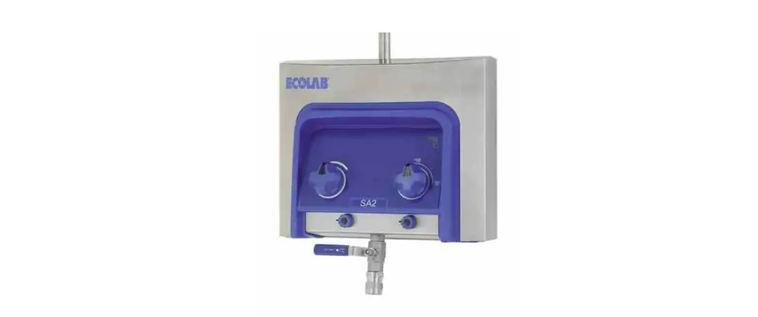
ECOLAB SA Series Advanced Satellite
Description
The satellite in the Chameleon ran-ge is a complete hygiene station which is connected to a booster or a main station. Therefore the satel-lite must be supplied with water in sufficient quantity, (power supply) compressed air, detergent(s) and disinfectant. The station is then ready for hygiene duties.The Advanced satellite incorpora-tes a unique pneumatically con-trolled valve system that ensures injectors are flushed with water between hygiene functions. De-pendent on the model the system can work automatically or pneuma-tically via the selector.
Important
Do not use the water from the system for applications other than cleaning.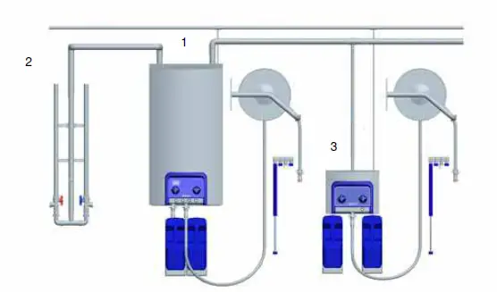
Using hygiene Chemicals
The Advanced Satellite has been prepared to use Ecolabs European palette of detergents and disinfec-tants.
Warning:
Do not change the set-tings made or recommended by the supplier of hygiene chemicals. A typical installation of the Advan-ced series is shown in fig. 1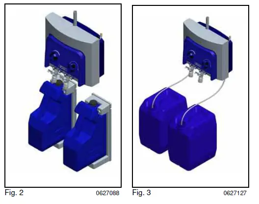
Detergents are supplied either from the User Pack System, which can be ordered and delivered as an accessory or from separate standard cans. Hygiene chemicals can also be established through piping systems.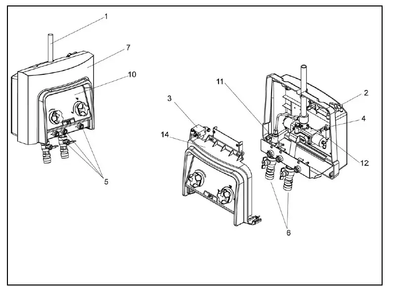
Layout SP
Satellites
SP11-SP21-SP22-SP32-SP33 (Fig. 4).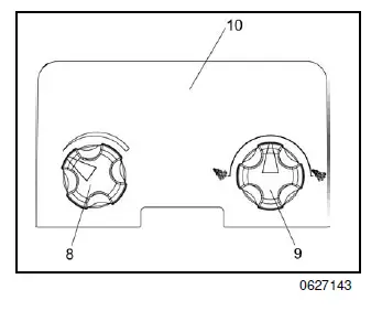
- Water inlet
- Check valve, air
- Air Filter unit
- Injector block
- Dosing valves
- Quick coupling with check tap
- Cover
- Air regulator
- Change-over switch, foam/rinse
- Operational area
- External Injector
- Non Return valve, air
- Change over valve
- Operational panel
Operating Diagrams
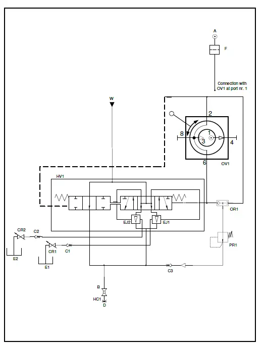
Satellite SP
- Ball valve.
- Filter.
- Check valve.
- Detergent regulator.
- Ejector.
- Hydraulic valve.
- Hose connection.
- Operator valve.
- OR element.
- Pressure regulator.

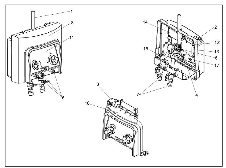
Layout SA
Satellites
SA11-SA21-SA22-SA32-SA33(Fig. 4).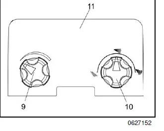
- Water inlet
- Check valve, air
- Air Filter unit
- Injector block
- Dosing valve
- Flow sensor
- Quick coupling with check tap
- Cover
- Air regulator
- Change-over switch, foam/rinse
- Operational area
- Non Return valve, air
- Solenoid valve
- Electrical Box
- External Injector
- Operation panel
- Change over valve
Operating Diagrams iht
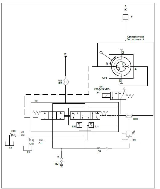
- Solenoid valve.
- Chemistry regulator.
- Ejector.
- Hydraulic valve.
- Hose connection.
- Operator valve.
- OR element.
- Pressure regulator.
- Control board connection.
Maintenance
The Satellite is maintenance-free.
Start
New system
In order to ensure a problem-free start up of a new system the pipe system must be flushed and bled.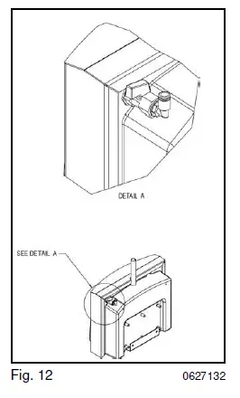
Bleeding the pipe system
- Turn on the water supply to rinse and bleed the entire system. Open the tap furthest away until no air or dirt comes out. Then rinse and bleed the next tap and continue until the tap closest to you has been rinsed and bled.
- Mount satellites.
Daily operation
- Check that water- and air sup-plies for the system are open.(see A, Fig.12, air)
- Set the function that you want. Use the system referring to “User Guide” instructions
Rinsing the detergent supply
IMPORTANT
The detergent supply must always be rinsed thoroughly after use. Remains of detergent or disinfectants can clog the detergent supply so it needs to be rinsed or replaced. The fol-lowing procedure will clean the detergent supply for detergent and/or remains of disinfectants
- Remove User Pack, if any
- Hold the rinsing bottle with clean water tightly against the suction opening (with User Pack) or against the hose (without User Pack). Alterna-tively, you can place a User Pack with clean water in the holder or – without User Pack place the hose in a bucket of clean water.
- Activate the hose handle until clean water comes out of the nozzle (approx. 30 seconds).
Note:
This procedure should be followed for both detergent and disinfectant side if this is installed.
Service
Service may only be carried out by authorized and qualified personnel. Warning: The satellite must only be serviced when there is no pres-sure on the system.:
- Turn off the water and air sup-ply
- Turn of the power supply
- Depressurise the system.
Components
side (water, air, detergent) Maintenance-free If defective: Call service technician
Recycling and scrap-ping
Recycle the wrapping and scrap the machine according to recommendations from the local authorities.
Troubleshooting
Too low or unstable pressure.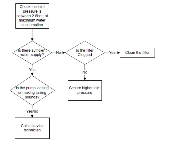
Unsatisfactory foam quality
No foam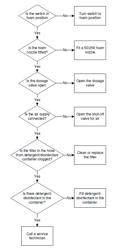
Recommended spare parts
The recommended spare parts are marked with * in the spare part manual.
Specifications
The most important specifications are shown on the serial plates on the main station/satellite and pump, respec-tively.
| Adv. | ||||
| Water | Unit | Pneumatic SP | Automatic SA | |
| Max. outlet pressure. | MPa (bar) | 0,4 (40) | 0,4 (40) | |
| Comsumption during rinsing. | L/min | 30 | 30 | |
| Comsumption during foaming. | L/min | 10 | 10 | |
| Min. supply prssure. | MPa (bar) | 1,2 (12) | 1,2 (12) | |
| Max. supply pressure. | MPa (bar) | 0,4 (40) | 0,4 (40) | |
| Min. water supply. | L/min | 30 | 30 | |
| Max. water temp. | °C | 70 | 70 | |
| Pipe dimension inlet Ø | inch | 1/2” | 1/2” | |
| Pipe dimension outlet Ø | inch | 1/2” | 1/2” | |
| Compressed air | ||||
| Min/Max air pressure | MPa (bar) | 0,5-1,0 (5-10) | 0,5-1,0 (5-10) | |
| Compressed air consumption | NL/min | 200 | 200 | |
| Pipe dimension inlet Ø | mm | 6 | 6 | |
| General | ||||
| Dimensions | mm | 330 x 403 x 215 | 330 x 403 x 215 | 330 x 403 x 215 |
| Weight | kg | 15 | 15 | 15 |
| Electricity | ||||
| Supply voltage | V | 1N/PE 110/230 V 85-0%…265+0% | 24 V DC ± 10% | |
| Frequency | Hz | 50/60 Hz 48-0%…62+0% | ||
| Power | W | 3 | ||


