
C S YO8 Yodalarm & Yodalight Series Clifford & Snell
Installation
- Installation must be carried out in accordance with the latest codes of practice by a qualified electrician.
- Check that the power supply is correct for the voltage rating of the alarm to be installed.
- Ensure that the power supply is disconnected prior to installation or maintenance to avoid electrical shock.
- The unit should be mounted to a wall or bulkhead formed of suitable material using the two mounting lugs projecting from the side of the enclosure.
- The lugs have an 10mm diameter mounting hole & sit on 250mm centres. The minimum recommended length of fixing screw is 30mm (not supplied).
- Avoid mounting the alarm where it could subjected to excessive vibration levels.
- All YA80 units require 2 additional ferrite beads (included in box) to be fitted on all input wires, 1 wire per hole. Failure to correctly install the ferrite beads will result in the unit not complying with the EN54-3 approval. (YL80 Ferrite Beads are factory installed).
Ingress Protection
To maintain the IP rating of the product, the below points must be observed.
- An IP66 cable gland is supplied with the product. This gland (or other suitably rated) must be used.
- When replacing the front cover, each of the four retaining screws must be torqued to 0.6Nm ±0.1Nm
Sound selection
- Ensure the supply is OFF before proceeding.
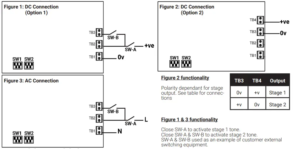
- All DC and AC units have 2 selectable alarm stages (see table on back of installation sheet for details) and are set via switches SW1 & SW2.
- Figure 1 (DC) & Figure 3 (AC) show wiring to activate alarm stages 1 & 2.
- Figure 2 shows a second option for DC wiring. This allows for activating a stage 1 or a stage 2 alarm tone depending on the polarity of the connection.
- All stage 1 alarm tones have a predetermined stage 2 alarm (see back of installation sheet), this will only sound if SW1 & SW2 are configured to the same tone.
Line integrity for DC systems only
- For 3 wire 2 stage alarm system, monitor via reverse polarity across TB1 & TB2.
- For 2 wire 2 stage alarm system, monitor via threshold, (applied voltage<1v) an end-of-line (E.O.L) resistor is required for line monitoring and should have a minimum resistance of 3k3 ohms and 0.5watts, wire-wound or metal film type.
AC Systems
A second stage alarm tone can be activated by applying an additional “L” connection to the TB3 terminal on the PCB, as shown in Figure 3.
Additional Voltage Options
- The Clifford and Snell YO8 series is also available in a 48vDC (F) option.
- The wiring for this voltage is the same as the 24vDC units as shown in Figure 1.
- Always confirm correct voltage is applied to relevant terminals.

YO8 Yodalarm/Yodalight Series
Consists of either the YA80 (Audible Unit only) or the YL80 (Combined Audible & Visual unit)
Connections for the YL80 units are made via a 6 way Terminal Block mounted in the base of the unit as shown in Figure 4 diagram below. Using connections shown, it is possible to independently control both Sounder and Beacon sections.
YL80 Wiring options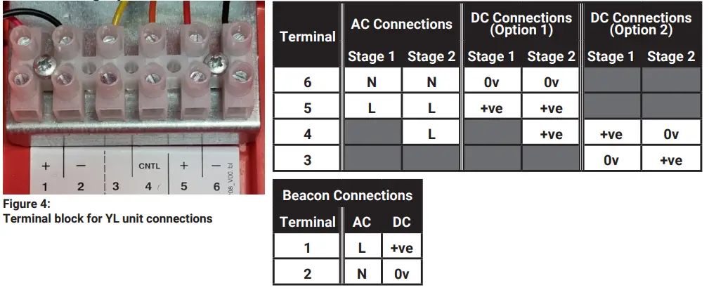
Features Include
- Termination: Up to 2.5mm2 cable
- Operating Temperature:
- Standard Variants -25oC to +70oC
- EN54-3 Approved -25oC to +55oC
- Enclosure Material: Fire Resistant & UV Stable UL94-5VB rated ABS
- Lens Material: Fire Resistant & UV Stable Polycarbonate
- Ingress Protection: Weatherproof to IP66
- Sound Pressure Level: 117dB(A) Max.
- Volume Control Adjustment: -18dB
- AC Supply: 50/60 Hz
Tone Table
| Frequency | Rept. | Second | Switches | dB(A) | |||||||
| Tone | Description | (Hz) | rate | Stage | 1 | 2 | 3 | 4 | 5 | Special Application | @ 1m (± 3dB) |
| 1* | Alternating | 800-1000 | 0.5 | 3 | I | I | I | I | I | Fire Alarms | 116 |
| 2 | Alternating | 2500-3100 | 0.5 | 4 | O | I | I | I | I | Security Alarms | 108 |
| 3 | Alternating (fast) | 800-1000 | 0.25 | 7 | I | O | I | I | I | Increased urgency | 117 |
| 4 | Alternating (fast) | 2500-3100 | 0.25 | 8 | O | O | I | I | I | Security deterrent | 108 |
| 5* | Alternating | 440-554 | 0.4/0.1 | 14 | I | I | O | I | I | AFNOR, France (NFS 32001) | 108 |
| 6 | Alternating | 430-470 | 1 | 14 | O | I | O | I | I | 107 | |
| 7 | Alternating (v.fast) | 800-1000 | 0.13 | 12 | I | O | O | I | I | 116 | |
| 8 | Alternating (v.fast) | 2500-3200 | 0.07 | 13 | O | O | O | I | I | 107 | |
| 9 | Alternating | 440-554 | 2 | 10 | I | I | I | O | I | Turn-out, Sweden | 110 |
| 10 | Continuous note | 700 | – | 1 | O | I | I | O | I | All-clear, Sweden | 110 |
| 11* | Continuous note | 1000 | – | 31 | I | O | I | O | I | 116 | |
| 12 | Continuous note | 1000 | – | 7 | O | O | I | O | I | 116 | |
| 13 | Continuous note | 2300 | – | 2 | I | I | O | O | I | 113 | |
| 14 | Continuous note | 440 | – | 9 | O | I | O | O | I | 105 | |
| 15* | Interrupted tone | 1000 | 2 | 31 | I | O | O | O | I | 115 | |
| 16* | Interrupted tone | 420 | 1.25 | 30 | O | O | O | O | I | AS2220, Australia | 105 |
| 17 | Interrupted tone | 1000 | 0.5 | 1 | I | I | I | I | O | 115 | |
| 18 | Interrupted tone | 2500 | 0.25 | 4 | O | I | I | I | O | 111 | |
| 19 | Interrupted tone | 2500 | 0.5 | 2 | I | O | I | I | O | 111 | |
| 20 | Interrupted tone | 700 | 6/12 | 10 | O | O | I | I | O | Pre-vital mess, Sweden | 111 |
| 21 | Interrupted tone | 1000 | 1 | 32 | I | I | O | I | O | 116 | |
| 22 | Interrupted tone | 700 | 4 | 10 | O | I | O | I | O | Air-raid, Sweden | 110 |
| 23 | Interrupted tone | 700 | 0.25 | 10 | I | O | O | I | O | Local warning, Sweden | 110 |
| 24 | Interrupted tone | 720 | 0.7/0.3 | 10 | O | O | O | I | O | Industrial alarm, Germany | 110 |
| 25 | Int,fast,rising volume | 1400 | 0.25 | 26 | I | I | I | O | O | 112 | |
| 26 | Fast siren | 250-1200 | 0.085 | 11 | O | I | I | O | O | 113 | |
| 27 | Rising constant, fall | 1000 | 10/40/10 | 17 | I | O | I | O | O | Industrial alarm, Germany | 117 |
| 28* | ISO 8201 Evacuation | 800-1000 | as std | 11 | O | O | I | O | O | Int’l evacuation alarm | 116 |
| 29 | Fast whoop | 500-1000 | 0.15 | 32 | I | I | O | O | O | 113 | |
| 30* | Slow whoop | 500-1200 | 4.5 | 12 | O | I | O | O | O | Evacuation, The Netherlands | 116 |
| 31* | Reverse sweep | 1200-500 | 1 | 11 | I | O | O | O | O | Evacuation, Germany | 115 |
| 32 | Siren | 500-1200 | 3 | 26 | O | O | O | O | O | 116 | |
Note: EN54-3 Compatible Tones are marked above with *.
Moflash Signalling Limited accepts no liability for any consequences following use of this document. Any technical specifications and products referred to within this document are subject to change without notice due to continual improvement and product development policies. All dB(A) figures are subject to environmental conditions. The units are sold under Moflash standard conditions of sale, available on request.
Additional resources, including installation sheet translations, certificates and DoCs are available from the www.moflash.co.uk website.
Moflash Signalling Limited, 11 Upper Conybere Street, Highgate, Birmingham, B12 0EB, UK


