WATTECO 50-70-166 Ventil O Remote Supervision of Controlled Mechanical Ventilation
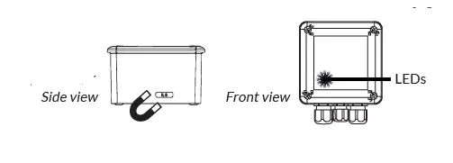
Start
ON :
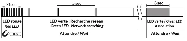
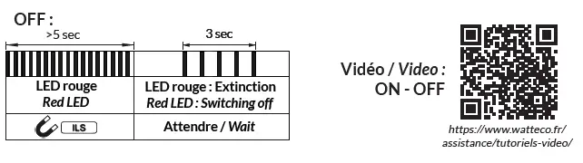
OFF :
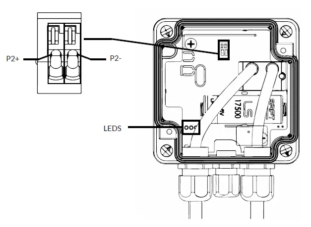
Connectors
Characteristics:
- Impedance: 1MΩ
- Tension : 0-30Vcc
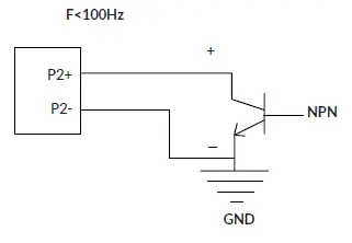
- Courant Delivered current: 3.5 µAFréquence signal max / Signal frequency max: 0-100 Hz
Wiring to open collector output
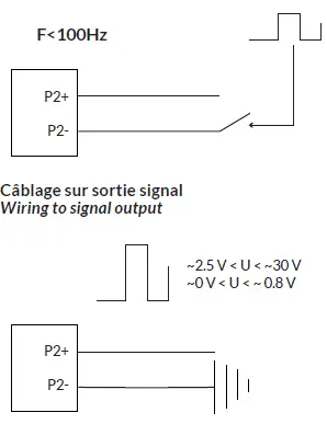
 Wiring to isolated dry contact output
 Status report or pulse count (if provided)
Use a flexible cable with a sheath with a diameter between 2.5mm and 6.5mm and single-stranded (or multi-stranded with crimp) 20-26AWG wires.
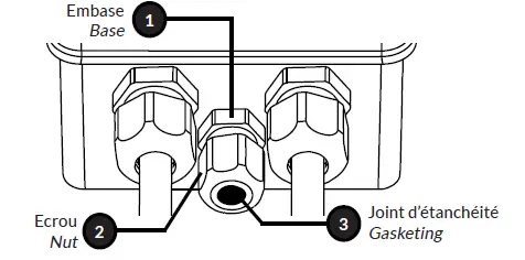
- Hold the base of the cable gland and slightly loosen the nut
- Thread the cable, taking care not to damage the seal
- Strip the cable for about 10cm. Adjust the cable and retighten the nut.
Strip each strand to a length of 5-6mm and connect as below:
Installation
Setting up
Opening Closure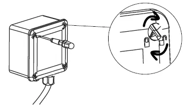 les 4 vis un ¼ de tour Unscrew the 4 screws by ¼ turn
Montage mural
Wall mounting
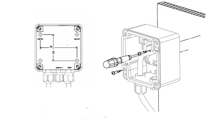
- Place the dowels and screw the housing to the wall
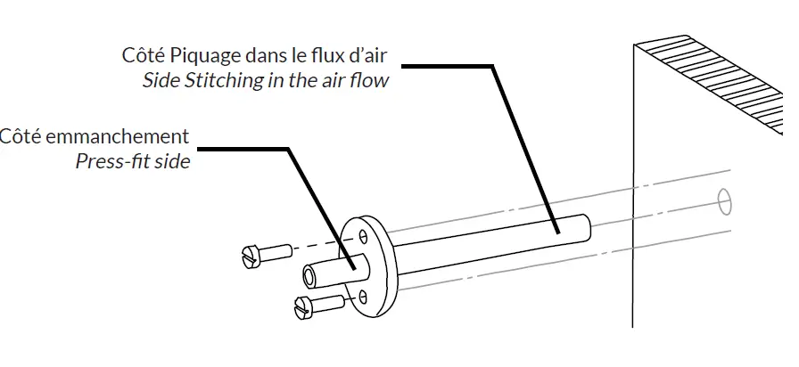
- Drill the duct to 8mm diameter
- Insert the air intake into the duct on the airflow side
- Fix the air intake to the duct with the 2 self-tapping screws provided
- Connect the flexible tube to the air intake by fitting it as tightly as possible
Orientation des tubes
Tube orientation
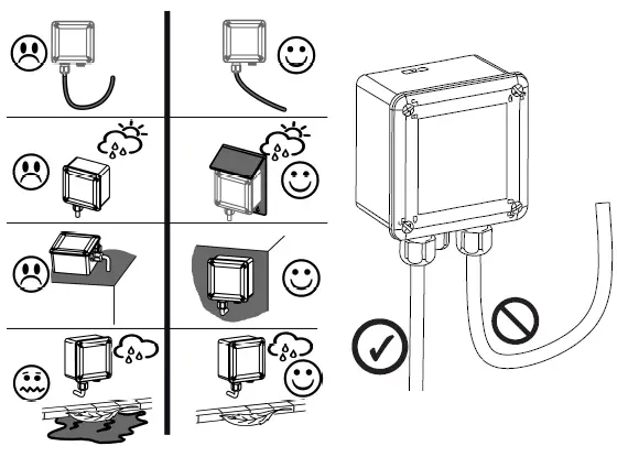
For the sensor to work properly, it is necessary to avoid fogging of the pipes.
Radio propagation
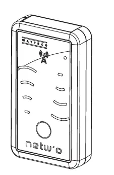
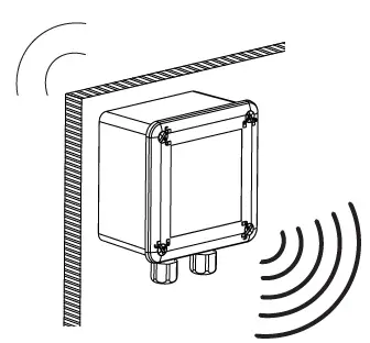 Check the radio coverage with the Netw’O.
 For the sensor communicates correctly, the number of obstacles should be limited to avoid excessive radio attenuation.
Characteristics
| Reference | 50-70-101 | 50-70-166 |
| Class | A | A |
| Power Level | +14 dBm | +14 dBm |
| Measure : de pression en 2 points The pressure difference at 2 points Entrée S0 / Input S0 | ✓ | ✓ ✓ |
| Antenna | Interne Internal | Interne Internal |
| Casing materials | ASA / PC | ASA / PC |
| Indicede protection IP rating | IP65 | IP65 |
 Watteco represented by JC LE BLEIS, declares that the radio equipment type 50-70-166 / 50-70-101 is in conformity with Directive 2014/53/EU (RED) and UKCA. The full text of the EU and UKCA Declaration of Conformity is available at the following web address: https://www.watteco.com/assistance/download-center/


