![]() Installation plan
Installation plan
Heat pump tumble dryer 
PDR 908 HP en-AU, NZ
11 276 500/04
It is essential to read the operating and installation instructions before installation and commissioning.
This prevents both personal injury and damage to the appliance.
Legend:
| Connection required | |
| AL | Exhaust air |
| ASK | Condensate drain hose |
| B | Appliance anchoring |
| EL | Electrical connection |
| F | Appliance feet, adjustable |
| KG | Payment system |
| KGA | Payment system connection |
| KLA | Cooling air vent |
| Connection optional or required, depending on model | |
| KLZ | Cooling air intake |
| PA | Equipotential bonding |
| SLA | Peak load connection |
| APCL SST | Box plinth |
| APCL OB | Open plinth |
| APCL 001 | Washer-dryer stacking kit |
| XKM | Communication module |
| ZL | Air intake |
Technical changes and errors excepted.
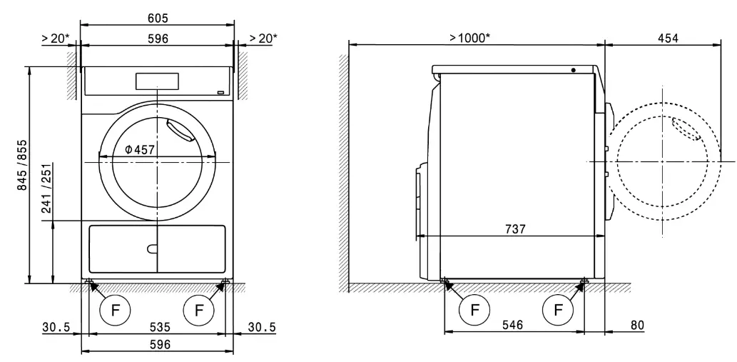
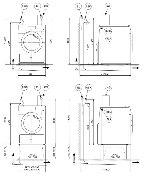
Appliance dimensions
- The wall spacers are recommended for making service work easier. The machine may be pushed against the wall if installation conditions mean there is limited space.
 | 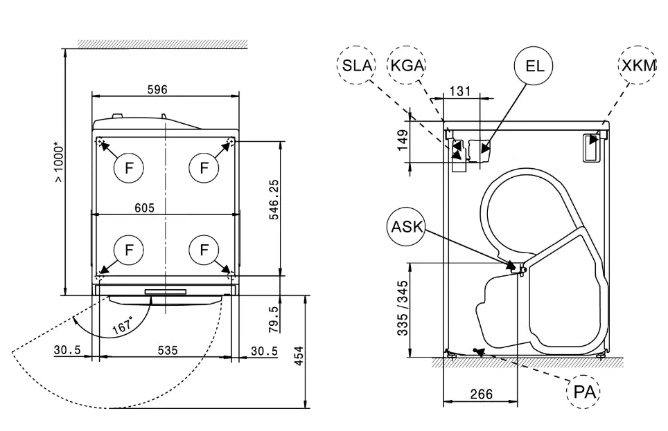 |
Installation
- The wall spacers are recommended for making service work easier. The machine may be pushed against the wall if installation conditions mean there is limited space.
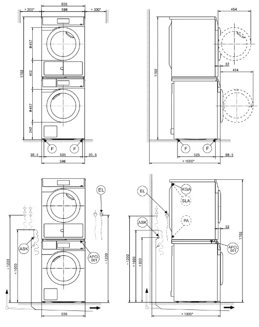
Washer-dryer stack
- The wall spacers are recommended for making service work easier. The machine may be pushed against the wall if installation conditions mean there is limited space.

- The wall spacers are recommended for making service work easier. The machine may be pushed against the wall if installation conditions mean there is limited space.
Technical data
| PDR 908 HP | ||
| Drying system | Heat pump | |
| Drum volume | l | 130 |
| Load Capacity | kg | 8 |
| Door opening diameter | mm | 370 |
Electrical connection (EL )
| Standard voltage (AU, NZ) | 1N AC 230 V | |
| Frequency | Hz | 50 |
| Total rated load | kW | 1.44 |
| Fuse rating | A | 1 x 10 |
| Supply cable min. cross-section | mm² | 3 x 1.0 |
| Supply cable with plug | ||
| Length of supply cable | mm | 2000 |
| Non-standard voltage MAR 230 (Marine) | 1N AC 230 V | |
| Frequency | Hz | 60 |
| Total rated load | kW | 1.2 |
| Fuse rating | A | 1 x 10 |
| Supply cable min. cross-section | mm² | 3 x 1.5 |
| Supply cable with plug | ||
| Length of supply cable | mm | 2000 |
Conden sate drain hose (ASK )
| Max. drainage temperature | °C | 70 |
| Max. transient flow rate | l/min | 3.6 |
| On-site hose sleeve for drain hose | mm | 10 x 30 |
| Drain hose (internal diameter) | mm | 10 (DN10) |
| Length of drain hose | mm | 1500 |
| Max. delivery head (from lower edge of machine) | mm | 1000 |
Equipo tenti albo nding (PA)
| Appliance connection (separate kit required) |  |
| XC I -B o x / XC I -AD in ter face |
| Peak-load / energy man age men t (SL A) | |
| Appliance connection (with XCI-Box) | |
| Payment system conn section n (K GA) | |
| Connection of payment systems (with XCI-Box / XCI-AD) | |
| Communi cati on mod ul e (XK M) | |
| Communication module KXM 3200 WL PLT | |
| I n stallationon appliance feet (F ) | ||
| No. of appliance feet | No. | 4 |
| Appliance foot, height-adjustable with thread | mm | ± 5 |
| Appliance foot diameter | mm | 31.7 |
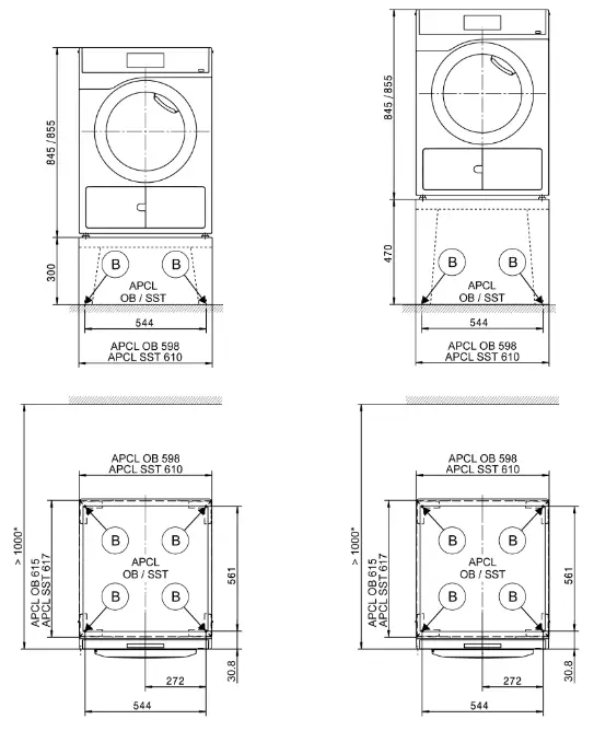
Anchoring (B )
Anchoring of Miele plinths
| Miele plinth installation (fasteners included) | | |
| Required anchor points | No. | 4 |
| Wood screws according to DIN 571 | mm | 8 x 65 |
| Wall plugs (diameter x length) | mm | 12 x 60 |
Plinth floor anchoring (to be provided on site)
| Appliance installation on on-site base (concrete or masonry) | | |
| Min. plinth installation footprint (W/D) | mm | 600/650 |
| Wood screws according to DIN 571 | mm | 6 x 50 |
| Wall plugs (diameter x length) | mm | 8 x 40 |
![]() = standard, = optional, + = only on request, – not available
= standard, = optional, + = only on request, – not available
| Ap p li an ce d ata | PDR 908 HP | |
| Overall appliance dimensions (H/W/D) | mm | 850/605/777 |
| Casing dimensions (H/W/D) | mm | 850/596/737 |
| Site-access dimensions (H/W) | ||
| Min. site-access opening (excl. packaging) | mm | 900/605 |
| Installation dimensions | ||
| Side gap | mm | 20 |
| Recommended side gap – washer-dryer stack | mm | 300 |
| Recommended distance to the opposite wall from appliance front | mm | 1000 |
| Weights and floor loads | ||
| Appliance weight (net weight) | kg | 73 |
| Max. floor load in operation | N | 925 |
| Emissions | ||
| Sound pressure level (in accordance with EN ISO 11204/11203) | dB(A) | <70 |
| Heat dissipation rate to the installation site | W | 950 |
Installation and planning notes
Installation requirements
The tumble dryer should only be connected to a power supply provided in accordance with all applicable local and national legislation and regulations.
In addition, all regulations issued by the appropriate utilities as well as standards relating to occupational safety and all applicable valid regulations and technical standards must be observed.
General operating conditions
Ambient temperature in installation room: +2 °C to +35 °C. Air drawn in for use in the drying process will be warm when it is expelled back into the room by the tumble dryer. You must therefore ensure that the room is sufficiently ventilated, particularly if the appliance is located in a small room.
Make sure that the room temperature is not too high. If there are other heat-producing appliances in the room in which the dryer is located, make sure the room is well ventilated and switch the other appliances off, if possible. Otherwise, running times and energy consumption could be increased.
Electrical connection
This tumble dryer is supplied with a mains cable with molded plug. The appliance may only be connected to an electrical system that conforms to the national and local codes and regulations. Do not connect the machine via an extension lead or power board. They do not guarantee the required safety of the appliance (e.g. danger of overheating and fire). The data plate indicates the nominal power consumption and the appropriate fuse rating. Compare the specifications on the data plate with those of the electrical power supply. If the appliance is hard wired, an all-pole disconnection must be provided on site. When switched off, there must be an all-pole contact gap of at least 3 mm in the isolator switch (including circuit breakers, fuses, and relays according to AS/NZS 3000). The plug connector or isolator switch should be easily accessible at all times. If the appliance is disconnected from the electricity supply, the isolator must be lockable or the point of disconnection must be monitored at all times. New connections, modifications to the system or servicing of the earthing conductor, including determining the correct fuse amperage, must be carried out by a qualified electrician, as they are familiar with the pertinent regulations and the specific requirements of the electric utility company. References to cable cross-sections in the technical data refer only to the required mains cable. Please consult relevant local and national regulations when calculating any other wire gauges.
Condensate drain hose
The condensed water is pumped away through the drain hose which is located at the back of the dryer.
The condensate is drained via a drain pump with a 1 m delivery head. For the water to drain freely, the hose must be free of kinks. The swivel elbow at the end of the hose can be turned in either direction or removed as needed. In certain situations, this tumble dryer must be fitted with a non-return valve (optional accessory). Without a non-return valve, water could flow back into the tumble dryer or be drawn back in and leak out. This can cause damage.
Drainage options:
- Connected securely to a trapped waste pipe. Use a non-return valve if the end of the hose could possibly become submerged in water.
- Connected to a laundry trough or washtub drain outlet. Always use a non-return valve.
- Connected to a floor drain (gully). Always use a non-return valve.
- Connected over the rim of a laundry trough or wash tub. Secure the drain hose carefully (e.g. by tying it) to make sure it cannot slip. Otherwise, water may escape and cause damage. Use a non-return valve if the end of the hose could possibly become submerged in water.
Equipotential bonding
If necessary, equipotential bonding with good galvanic contact must be guaranteed in compliance with all applicable local and national installation specifications.
Connection material for equipotential bonding must be provided on site or using a kit available from Miele.
Peak load/energy management
The tumble dryer can be connected to a peak load or energy management system using an optional kit.
When the peak load function is activated, the heating is deactivated.
A message appears in the display to inform you of this.
The programme is resumed automatically when the peak load system reactivates the heating.
Payment system
The tumble dryer can be fitted with a single-machine payment system as an optional accessory using an optional kit (XCI-Box / XCI-AD). The programming required for connecting a payment system can be carried out during the initial commissioning process. After initial commissioning, changes may only be made by your Miele dealer or by Miele Professional Service.
Interface
The tumble dryer can be retrofitted with a KXM 3200 WL PLT communication module.
This module can be used as a Wi-Fi or LAN interface.
The LAN interface provided via the module complies with AS/NZS 60950. The LAN connection uses a RJ45 connector in accordance with EIA/TIA 568-B.
Installation and anchoring
The machine must be installed on a perfectly smooth, level and firm surface which is able to withstand the quoted loads. The floor load created by the machine is concentrated and transferred to the installation footprint via the machine’s feet.
The tumble dryer should be leveled in both directions with the aid of adjustable feet.
Plinth installation
The tumble dryer can be installed on a plinth (open or box plinth, available as an optional Miele accessory) or on a concrete plinth to be provided on-site.
The quality of the concrete and its strength must be assessed according to the machine load. Ensure that any raised concrete plinth is adequately bonded to the floor below.
Washer-dryer stack
The tumble dryer can be installed as a washer-dryer stack together with a Miele washing machine. A stacking kit (optional accessory) is required for this.
The stacking kit must be installed by Miele Professional Service or an authorized Miele service technician.
Miele Australia Pty. Ltd.
ACN 005 635 398
ABN 96 005 635 398
Melbourne: Level 4, 141 Camberwell Road
Hawthorn East, VIC 3123
Telephone: 1300 731 411
[email protected]
www.miele.com.au/professional
[email protected]
Miele New Zealand Limited
IRD 98 463 631 8 College Hill
Freemans Bay Auckland 1011
New Zealand
Telephone: 0800 4 MIELE (0800 464 353)
www.miele.com.au/professional
[email protected] Miele Global Headquarters: Miele & Cie. KG
Carl-Miele-Straße 29, 33332 Gütersloh, Germany


