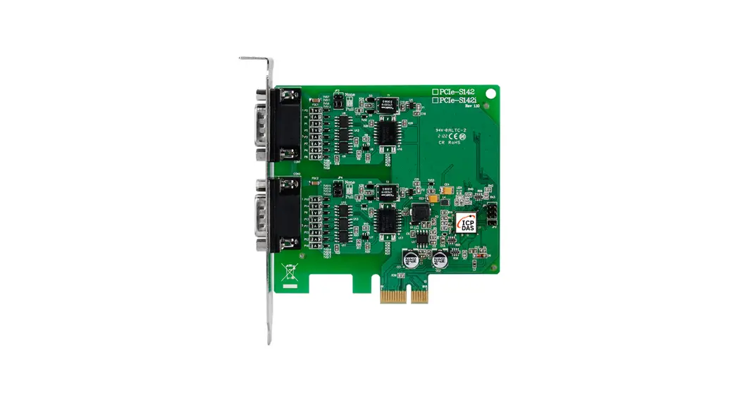
![]() PCIe-S142i Serial Communication Board
PCIe-S142i Serial Communication Board
User Manual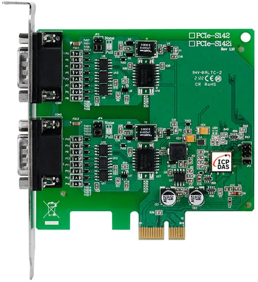
What’s in the Shipping Package?
The package includes the following items:
- PCIe-S112 or PCIe-5142

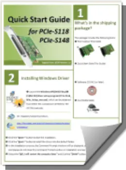
- Quick Start Guide (This Guide)

Installing Windows Driver
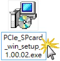
- Launch the Windows XP/7/8/10/2012/ 2016 (32/64-bit) driver setup program (PCIe_SPCard_Win_Setup_1.00.02.exe), which can be obtained from ICP DAS via the link given below.

 https://www.icpdas.com/en/download/index.php?nation=US&kw=PCIe+Series+Card+Windows+Driver
 - Click the “Next>” button to start the installation.
- Click the “Next>” button to install the driver into the default folder.
- In the installation process, the Command Prompt windows will be displayed, don’t care. And please do not close this Command Prompt window in the installation process.
- Select the “NO, I will restart the computer later” and click the “Finish” button.
Installing the Hardware
- Shut down and power off your computer.
- Remove the cover from the computer.
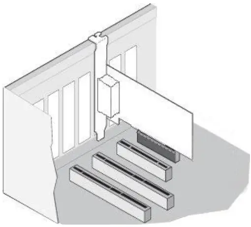
- Select an unused PCI Express slot.
- Carefully insert your PCIe-S1x2 card into the PCI Express slot.
- Replace the PC cover.
- Power on the computer.
- Follow the prompt message to finish the Plug & Play steps.
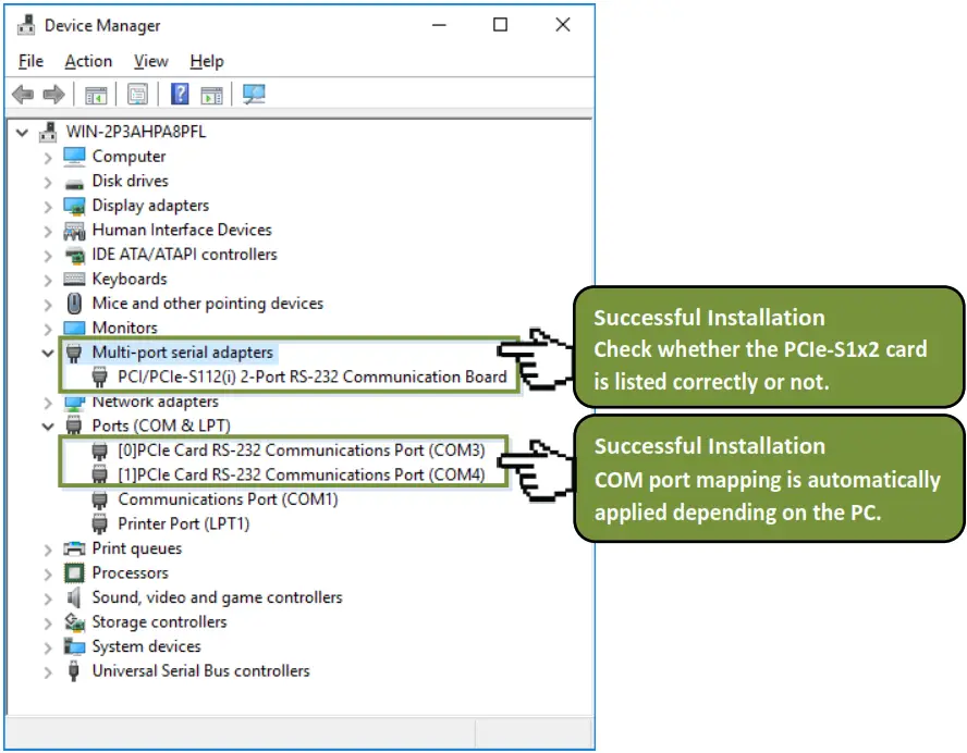
- Please open the “Device Manager” to verify the COM port installation, as follows steps:
8-1: In Windows 7, Click the “Start” button, and then click “Control Panel”.
8-2: Click “System and Maintenance”, and then click “Device Manager”.
8-3: Verify that the COM ports of PCIe-S112/5142 card are listed correctly.
Manual COM Port Configuration
If the auto-configuration for COM Port is messy or that is not what you need, you can change the COM port mappings. For detailed configuration steps, please refer to the following steps:
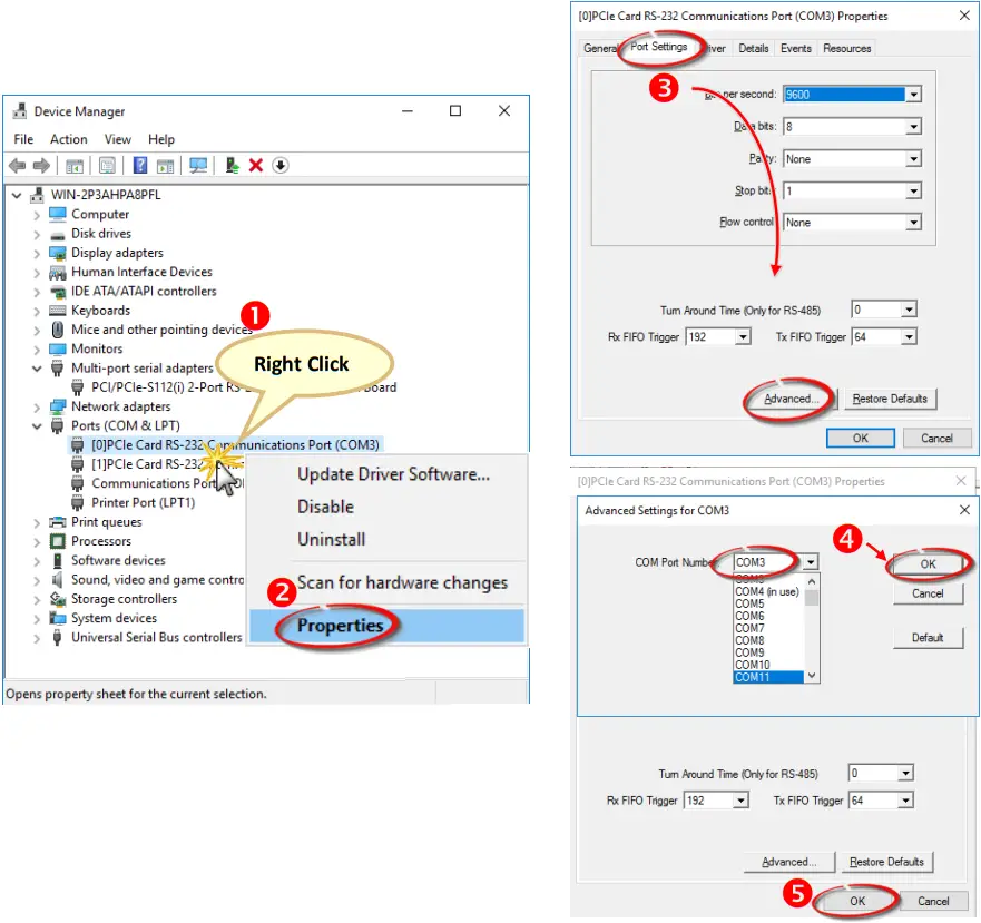
- Open Windows Device Manager and right-click the serial port of the PCIe-S1x2 series card.
- Select the “Properties” item from the popup menu.
- Click the “Port Settings” tab and click the “Advanced…” button.
- Select the appropriate COM Port number from the “COM Port Number:” drop-down options and click the “OK” button. Note that the COM port display “(in use)” means this COM port is being used. Therefore, please do not select it.
- Click the “OK” button in the “Properties” dialog box.
- Restart your computer to complete the configuration.

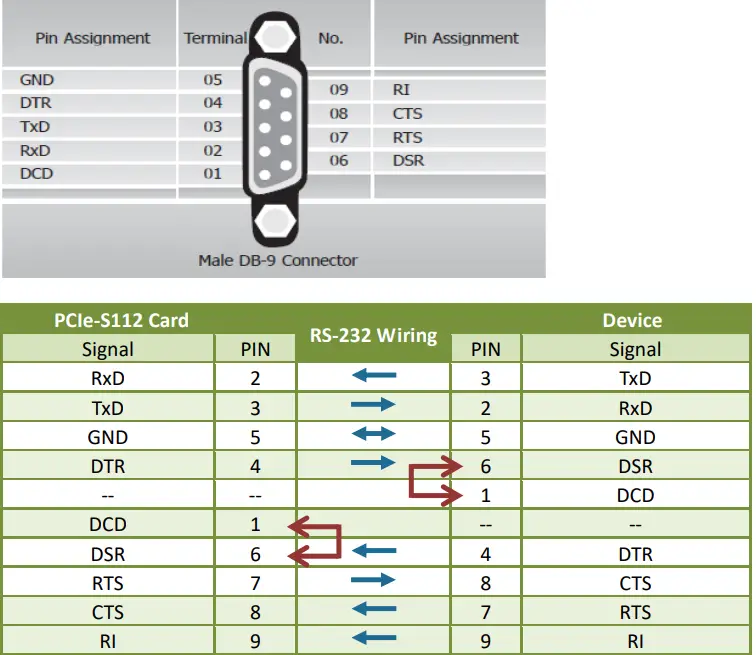
Pin Assignments and RS-232 Cable Wiring for PCIe-S112(i)
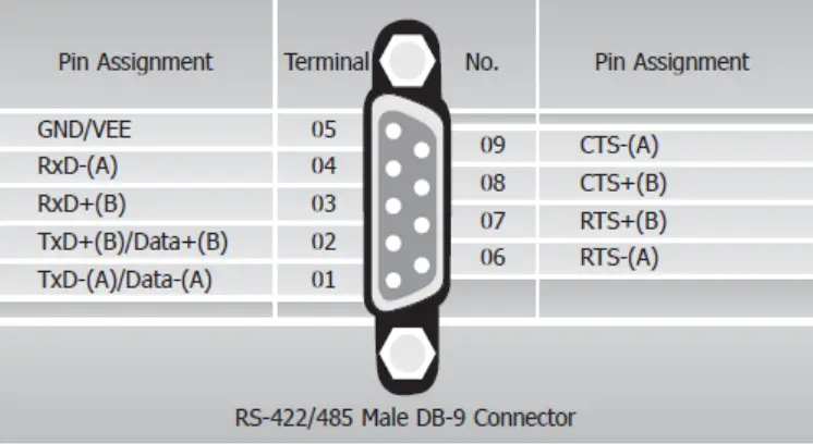
Pin Assignments and RS–422//485 Cable Wiring for PCIe-S142(ii)
| PCIe-S142 Card | RS-485 Wiring | Device | ||
| Signal | PIN | PIN | Signal | |
| DATA- | 1 | 1 | DATA- | |
| DATA+ | 2 | 2 | DATA+ | |
Note: The RS-485 bus is a differential (balanced) signal, thus you cannot wire the Data+ with Data- directly for a single port loop-back test. It will not work at all.
| PCIe-S142 Card | RS-422 Wiring | |||
| Signal | PIN | PIN | Signal | |
| TxD- | 1 | 4 | RXD- | |
| TxD+ | 2 | 3 | RxD+ | |
| RxD+ | 3 | 2 | TxD+ | |
| RxD- | 4 | 1 | TxD- | |
| GND | 5 | 5 | GND | |
| RTS- | 6 | 9 | CTS- | |
| RTS+ | 7 | 8 | CTS+ | |
| CTS+ | 8 | 7 | RTS+ | |
| CTS- | 9 | 6 | RTS- | |
Self-Test Wiring
Step 1: Connect the DN-09-2 terminal board (optional) to the PC1e-Slx2 series card using the CA-0910F cables (optional). 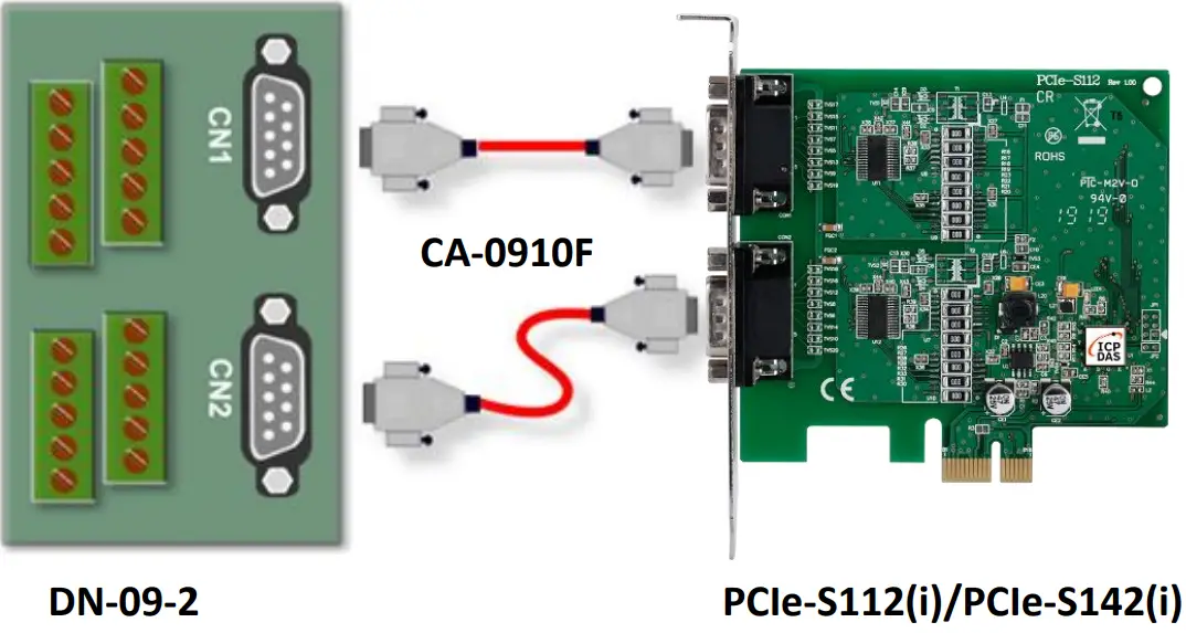 Step 2: Wire Port 0 and Port l.
▻ PCIe-S112(i) card (RS-232 Wiring): Shorting the RxD, TxD, and GND pins of both Porto and Port. 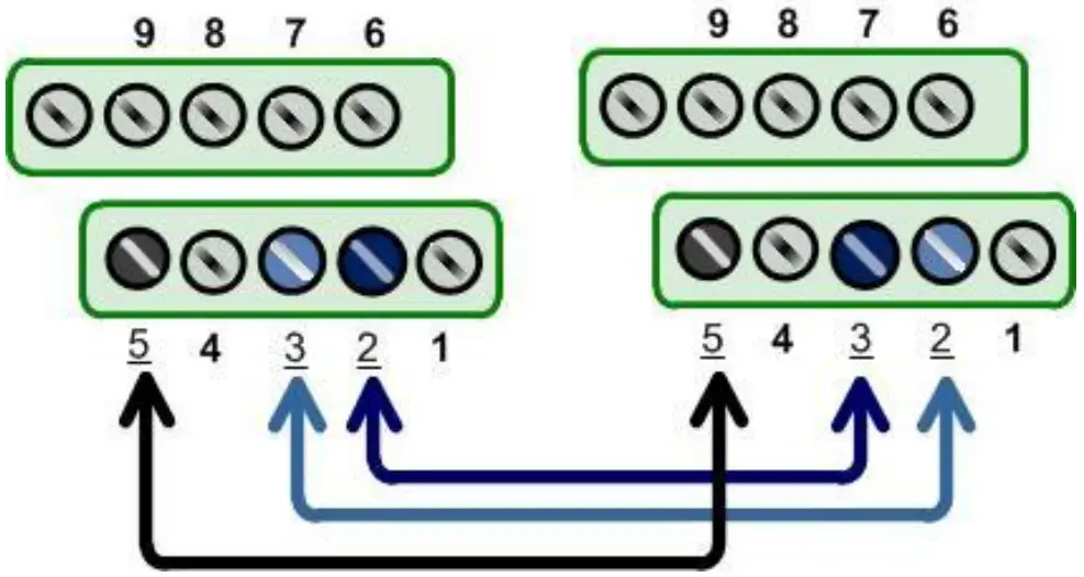
| Port0 | PIN | PIN | Port1 | |
| Signal | Signal | |||
| TxD0 | 3 | 2 | RxD1 | |
| RxD0 | 2 | 3 | TxD1 | |
| GND | 5 | 5 | GND |
▻ PCIe-S114(i) card (RS-485 Wiring): Shorting the Port0 Data+ and Portal Data+ and the Port0 Data- and Portal Data- pins.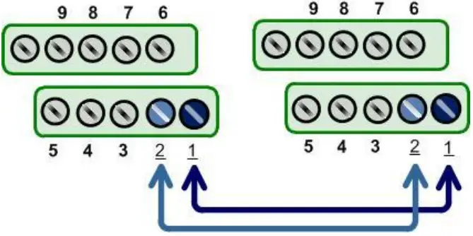
| Port0 | PIN | PIN | Port1 | |
| Signal | Signal | |||
| Data0- | 1 | 1 | Data1- | |
| Data0+ | 2 | 2 | Data1+ |
Execute the Test Program
Step 1: Execute the Test2COM.exe program, which can be downloaded from: 
![]() https://www.icpdas.com/en/download/index.php?nation=US&kw=Test2COM
https://www.icpdas.com/en/download/index.php?nation=US&kw=Test2COM
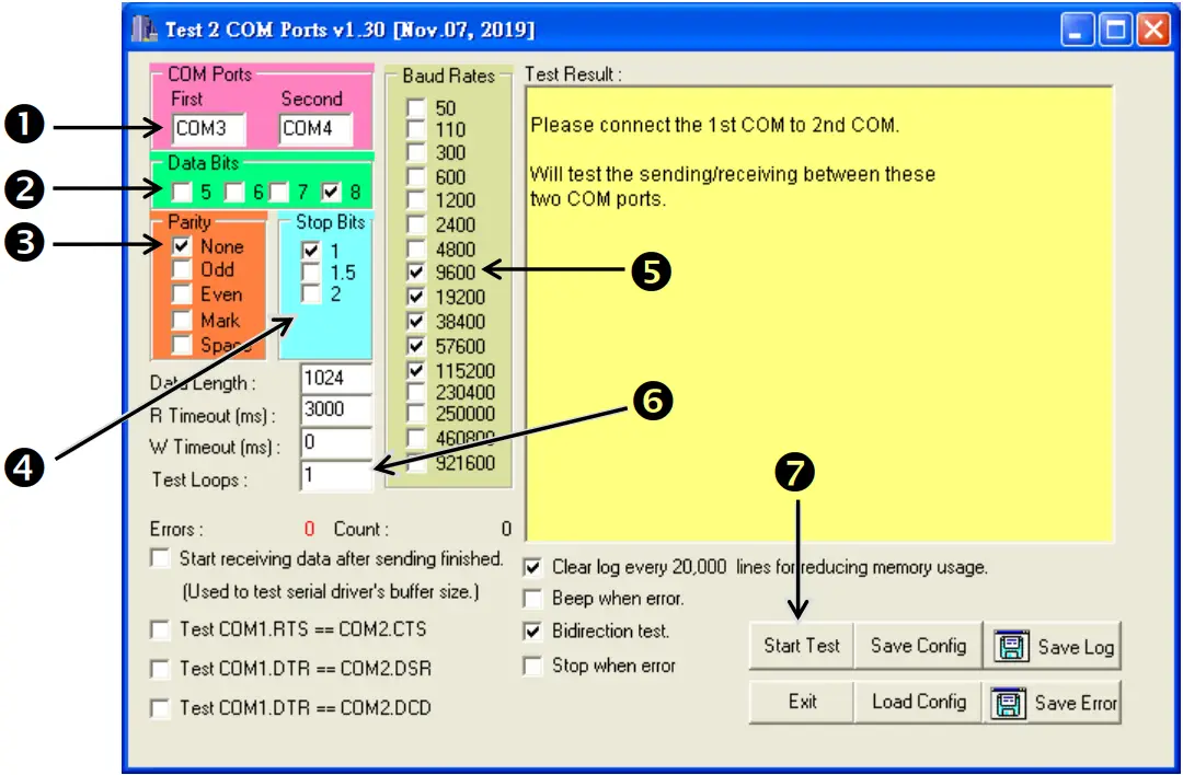
Step 2: Set the appropriate COM Ports, Baud Rate and Data Format information to the values shown in the image below.
- COM Ports: Enter COM3 (First), COM4 (Second)
- Data Bits: Check “8”
- Parity: Check “None”
- Stop Bits: Check “1”
- Baud Rates: Check values 9600 to 115200
- Test Loops: Type “1”
- Click “Start Test” to begin the test.

Successful Testing
Once the test is complete, verify the test results.
If the result indicates that the test was successful, the expanded COM Port is ready-to-use. 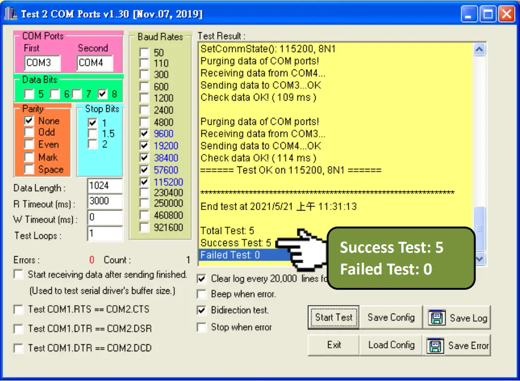 Related Information
- PCIe-S112(i)/PCIe-S142(i) card product page:
https://www.icpdas.com/en/product/guide+IndustrialCommunication+SerialCommunicationn+Multi-portSerial Board#793 - DN-09-2 and CA-0910F product page (optional):
https://www.icpdas.com/en/product/DN-09-2
https://www.icpdas.com/en/product/CA-0910F - Software and documentation:
https://www.icpdas.com/en/download/index.php?model=PCIe-S112
Copyright © 2021 ICP DAS Co., Ltd.
All Rights Reserved.
E-mail: [email protected]


