![]()
EMP-2848M Series Hardware
User Manual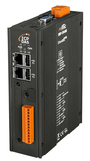 EMP-2848M Series
Hardware Manual
Ver. 1.0.0, AUG. 2022
EMP-2848M Series Hardware
WARRANTY
All products manufactured by ICP DAS are warranted against defective materials for a period of one year from the date of delivery to the original purchaser.
WARNING
ICP DAS assumes no liability for damages consequent to the use of this product. ICP DAS reserves the right to change this manual at any time without notice. The information furnished by ICP DAS is believed to be accurate and reliable. However, no responsibility is assumed by ICP DAS for its use, nor for any infringements of patents or other rights of third parties resulting from its use.
COPYRIGHT
Copyright © 2022 by ICP DAS. All rights are reserved.
TRADEMARK
Names are used for identification only and may be registered trademarks of their respective companies.
CONTACT US
If you have any questions, please feel free to contact us via email at: [email protected], [email protected]
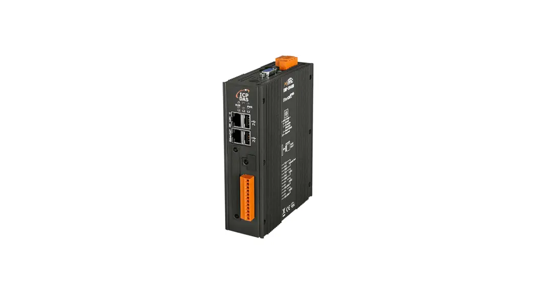
Introduction
The EMP-2848M series is a Softly based Ether CAT master with an integrated multi-axis motion control kernel. The programmable automation controller combines compact size, economy, flexibility, and excellent performance and is the ideal partner for small and medium-sized motion control applications where cost and space- constrains is an deciding factor.
The high-performance quad-core Cortex-A53 processor together with the Real-Time Linux (RT-Preempt) operating system and built in Soft PLC ensure fast, deterministic and real-time behavior in the motion control applications. The integrated, configurable high-speed Ether CAT master can be connected to any standard, 3rd party Ether CAT slave, such as I/Os, servo motor, stepper motor, encoder, etc.. The Ether CAT master can synchronously update up to 128 slaves including 16 servo/stepper drives within a cycle time of 500 microseconds.
The integrated web server assists the user in configuring and diagnosing the Ether CAT networks, and testing of motion control functions. Win-GRAF workbench is a programming software that ICPDAS developed according to the international standard IEC 61131 and aimed at achieving compatibility and reusability.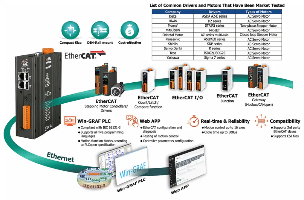
1.1. Specification
| Model | EMP-2848M |
| Software | |
| OS | Real-Time Linux (RT-Preempt, Kernel 4.14.98) |
| Programming languages per IEC 61131-3 | Instruction List (IL) |
| Ladder Diagram (LD) | |
| Function Block Diagram (FBD) | |
| Structured Text (ST) | |
| Sequential Function Chart (SFC) | |
| Development Software | Win-GRAF |
| Protocols | Modbus TCP, Master/Slave Modbus RTU/ASCII, Master/Slave |
| Ether CAT | |
| Motion Control | PL Copen Function Blocks |
| Main Unit | |
| CPU | Cortex-A53, Quad-core, 1.6GHz |
| SDRAM | LPDDR4 – 1GB |
| Storage | eMMC Flash 8GB MicroSD slot |
| LED Indicators | 1 x Run, 1 x Power, 3 x Ether CAT Runtime |
| Communication Ports | |
| Ethernet | 1 x RJ-45, 10/100/1000 Base-TX |
| Ether CAT | 1 x RJ-45 |
| USB | 2 x USB 2.0 |
| Console | RS-232 (RxD, TxD, GND); Non-isolated |
| COM1 | RS-232 (RxD, TxD, GND); Non-isolated |
| COM2 | RS-485 (Data+, Data-); 2500 VDC isolated |
| COM3 | RS-485 (Data+, Data-); 2500 VDC isolated |
| EtherCAT | |
| Cycle Time | 500μs (min.) |
| Number of Slaves | 128 |
| Number of Axes | 16 |
| Power | |
| Input Range | +12 ~ 48 VDC |
| Consumption | 7.2 W (0.3 A @ 24 VDC) |
| Mechanical | |
| Casing | Metal |
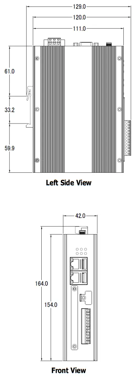
| Dimensions (W x L x H) | 42 mm x 164 mm x 129mm |
| Installation | DIN-Rail Mounting |
| Environmental | |
| Operating Temperature | -25 ~ +75 ℃ |
| Storage Temperature | -40 ~ +80 ℃ |
| Ambient Relative Humidity | 10 ~ 90% RH (non-condensing) |
Hardware Information
2.1. Appearance
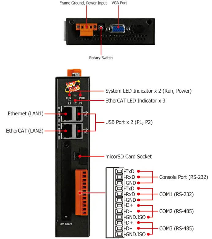
| Item | Description |
| LED Indicator | The details are showman below.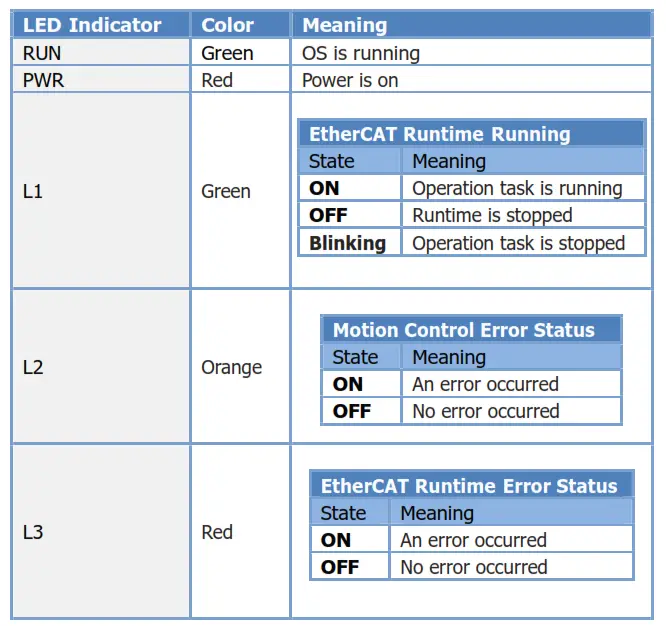 |
| Ethernet (LAN1) | The details are showman below.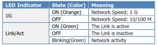 |
| Ether CAT | The Ether CAT master output port is used to manage the network, monitor the status of the slaves and exchange I/O data with slaves. Do not use a standard Ethernet switch for wiring between master and slave. For daisy chaining and branch connection, please use Ether CAT Junction module. |
| USB | Two USB 2.0 port that allows support for the USB devices such as mouse, keyboard or an external USB hard drive. |
| MicroSD slot | Supports up to 32 GB |
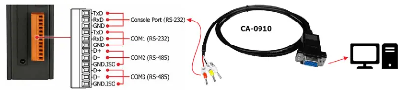
| Pin Assignment | ||||||
| Pin | Signal | Description | ||||
 | 1 | TxD | Console Port (RS-232) | |||
| 2 | RxD | |||||
| 3 | GND | |||||
| 4 | TxD | COM1 (RS-232) | ||||
| 5 | RxD | |||||
| 6 | GND | |||||
| 7 | TxD | COM2 (RS-485) | ||||
| 8 | RxD | |||||
| 9 | GND | |||||
| 10 | TxD | COM3 (RS-485) | ||||
| 11 | RxD | |||||
| 12 | GND | |||||
| VGA | Maximum resolution 1920×1080 | |||||
| Rotary Switch | Rotary Switch is an operating mode selector switch which provides seven functions related to the selection of the operating mode. | |||||
| Power Input and Frame Ground | There are 2 pins for power input and a pin for frame ground as follows: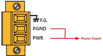 | |||||
2.2. Dimensions (Units: mm)
Mounting the Hardware
The hardware has simple rail clips for mounting reliably on a standard 44 mm DIN rail. 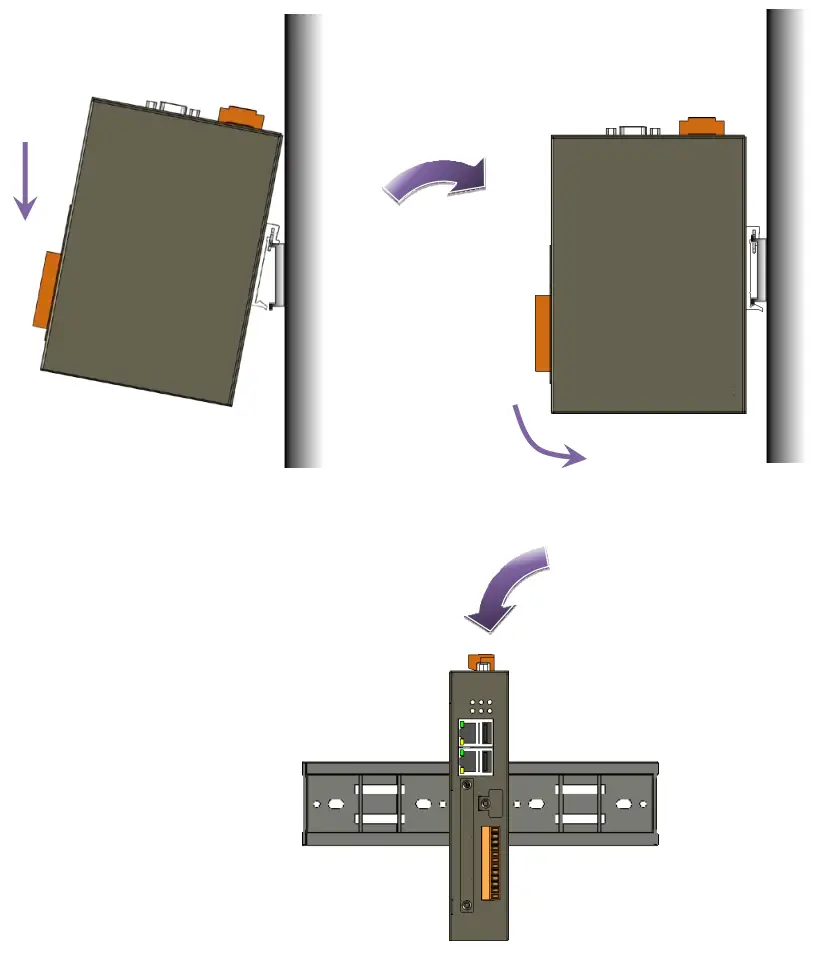
System Restore and Reset Default
This chapter describes how to use Rotary Switch to restore the system and reset the default.
| Rotary Switch | Mode | |
 | 0 | Normal mode |
| 1 | Restore system using SD card | |
| 2 | Reset default | |
| 3 | Delete configuration file |
4.1. Restore System Using microSD (Rotary Switch: 1)
[Restore the image to the microSD card]
- Download the latest version of the SD card system restore image from Download Center.
https://www.icpdas.com/tw/download/index.php?model=EMP-2848M - The file emp-2848m-system-restore-sd-xxxx-xx-xx.zip contains the emp-2848m-system-restore-sd-xxxx-xx-xx.img image file.
- Prepare a microSD card with at least 4GB of space. Use Draw Copy or Win32DiskImager tool to restore the image file to the SD card.
[Automatic system restore process]
- Insert the microSD card into the microSD slot and connect the keyboard and monitor to the USB and VGA ports, turn the Rotary Switch to 1, then turn on the power.
- Wait for the following message to appear on the screen, please enter y to start the automatic system restore process. This message will stay for 5 seconds waiting for user input, if the user does not enter, you can use the manual system restore process to restore.

- When the restore is successful, one long beeps from buzzer and “system restore successful” will be displayed, press any key to end. If the restore fails, three short beeps
from buzzer and “xxx restore failed” will be displayed.
- Finally, turn the Rotary Switch to 0 normal mode and reapply power.

[Manual system restore process]
- If the user does not want to connect to the keyboard and monitor, the Console Port can be used for manual system restore.
- Connect the CA-0910 female connector to the PC and the other side to the Console Port on the hardware pin.

- Insert the microSD card into the microSD slot and turn the Rotary Switch to 1, then turn on the power.
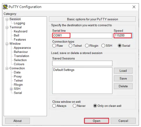
- Use an SSH/Telnet software, e.g. Putty, to connect to UA via the Serial connection.
Input your Serial line (default: COM1) and Speed (115200 for UA). And then click “Open” button.
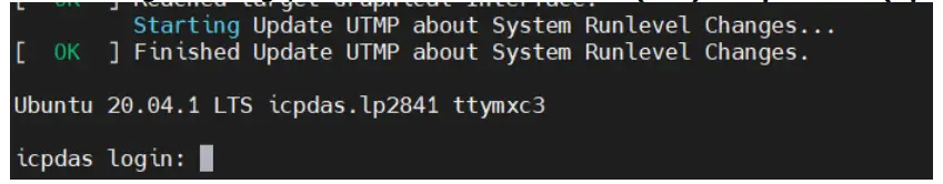
- After the login message, enter the default username (root) and password (ideas).

- Enter “cd recovery” to change the directory.

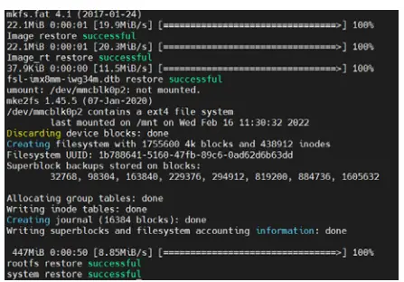
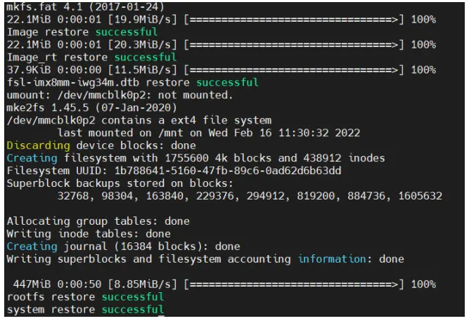
- Enter “./sys_recovery.sh” to run the system restore program, wait for the following message to appear, please enter ”y” to start the system restore process.

- When the restore is successful, one long beeps from buzzer and “system restore successful” will be displayed, press any key to end. If the restore fails, three short beeps
from buzzer and “xxx restore failed” will be displayed.
- Finally, turn the Rotary Switch to 0 normal mode and reapply power.


4.2. Restore System Using UUU Tool
If you cannot restore the system from the SD card, you can use this method to restore the system.
- Download the latest version of UUU system restore file from Download Center (emp-2848m-system-restore-uuu-xxxx-xx-xx.zip).
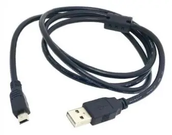
https://www.icpdas.com/tw/download/index.php?model=EMP-2848M - prepare a Mini USB cable.

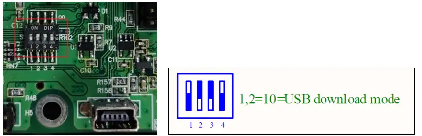
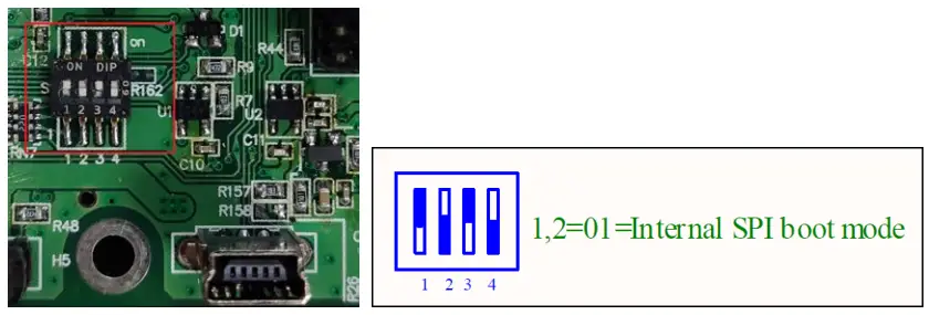
- Disassemble the hardware case and adjust the SW1 dip switch to USB download mode, as shown below.

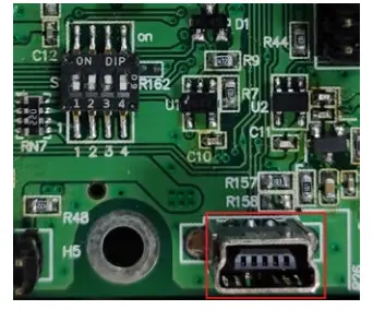
- Connect the Mini USB cable to the Mini USB connector (J4) of the module and the other end to the PC.

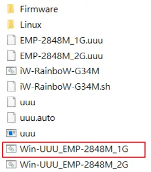
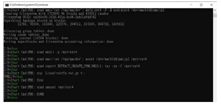
- Extract emp-2848m-system-restore-uuu-xxxx-xx-xx.zip file, and execute Win-UUU_EMP-2848M_1G.bat.

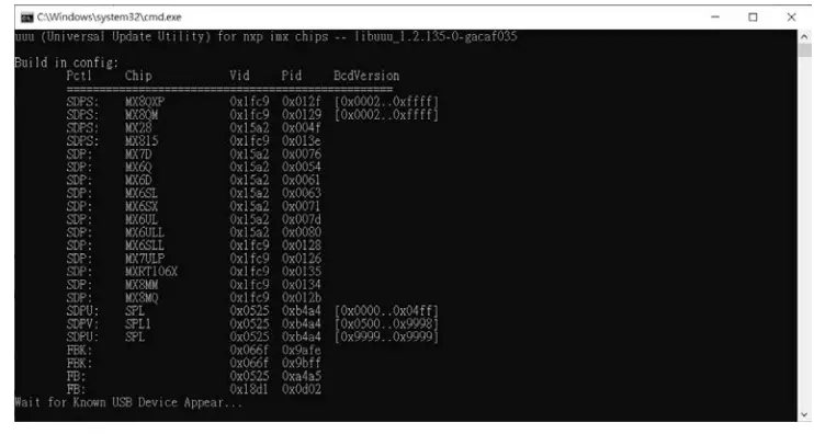
- Wait for “Wait for Known USB Device Appear” to appear in the command prompt.

- Turn on the module power, the system restore process will start, wait for “Start Cmd:FBK Done” to appear and show “Okay”, it means the system restore is successful.

- As shown in the figure below, adjust the SW1 DIP switch to the internal SPI boot mode and reapply power.

4.3. Reset Default (Rotary Switch: 2)
- Turn the Rotary Switch to 2 and turn on the power. Wait for the buzzer to beep every three seconds to indicate a successful reset of the default value.
Factory Default Settings Network IP (LAN1) 192.168.255.1 Netmask 255.255.0.0 Gateway 192.168.1.1 OS Account Username Password root ideas ideas ideas Web Account Username Password admin admin - Turn the Rotary Switch to 0 normal mode and reapply power.
4.4. Delete the Configuration File (Rotary Switch: 3)
- Turn the Rotary Switch to 3 and turn on the power. Wait for the buzzer to beep every three seconds to indicate successful deletion of the configuration file.
Configuration file
EtherCAT Delete the default ENI file Win-GRAF Delete the PLC program file - Turn the Rotary Switch to 0 normal mode and reapply power.
Revision History
| Revision | Date | Description |
| 1.0 | 2022/07 | Initial issue |
![]()
Copyright © 2022 ICP DAS CO., Ltd.
All Rights Reserved.


