![]() Operating Manual
Operating Manual
RS 1410-1002
Stock number: 205-0958
H87.0.01.DK2RS-2.0

About this documentation
Purpose of the document
– This document is intended as a quick reference option.
Legal notices
This document is entrusted to the recipient for personal use only. Any impermissible transfer, duplication, translation into other languages or excerpts from this operating manual are prohibited.
The manufacturer assumes no liability for print errors.
Further information
The software version of the product:
V1.3 or later
For the exact product name, refer to the type plate on the rear side of the product.![]() NOTE
NOTE
For information about the software version, press and hold the ON button to switch on the product for longer than 5 seconds. The series is shown in the main display and the software version of the product is shown in the secondary display.
Safety
Explanation of safety symbols
![]() DANGER
DANGER
This symbol warns of imminent danger, which can result in death, severe bodily injury, or severe property damage in case of non-observance.![]() CAUTION
CAUTION
This symbol warns of potential dangers or harmful situations, which can cause damage to the device or to the environment in case of non-observance.![]() NOTE
NOTE
This symbol indicates processes, which can have a direct influence on the operation or can trigger an unforeseen reaction in case of non-observance.
Foreseeable misuse
The fault-free function and operational safety of the product can only be guaranteed if applicable safety precautions and the device-specific safety instructions for this document are observed.
If these notices are disregarded, personal injury or death, as well as property damage can occur.![]() DANGER
DANGER
Incorrect area of application!
In order to prevent erratic behavior of the product, personal injury or property damage, the product must be used exclusively as described in the chapter Description in the operating manual.
– Do not use in safety / Emergency Stop devices!
– The product is not suitable for use in explosion-prone areas!
– The product must not be used for diagnostic or other medical purposes on patients!
– The product is not intended to come into direct contact with food. For measurement in foods, samples must be taken and discarded after the measurement!
– Not suitable for use with requirements on functional safety, e.g. SIL!
Safety instructions
![]() NOTE
NOTE
This product does not belong in children’s hands!
Intended use
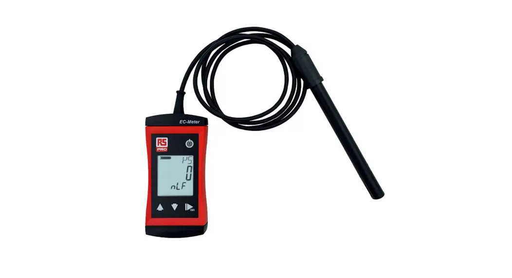
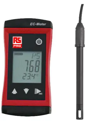
The product is designed for measuring the conductivity of liquids. The measuring cell is connected permanently.
The product at a glance
RS 1400 series
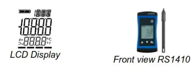
Display elements
Display
| Battery indicator | Evaluation of the battery status | |
 | Unit display | Display of units or type of mode, min/max/hold |
 | Main display | Measurement of the current conductivity value or value for min/max/hold |
| Auxiliary display | Corresponding temperature value for the value shown in the main display. If applicable, alternating with the temperature compensation. |
Operating elements
![]() On / Off button
On / Off button
| Press briefly | Switch on the product Activate / deactivate lighting |
| Long press | Switch off the product Reject changes in a menu |
![]() Up / Down button
Up / Down button
| Press briefly | Display of the min/max value Change value of the selected parameter |
| Long press | Reset the min/max value of the current measurement |
| Both simultaneously | Rotate display, overhead display |
 Function key
| Press briefly | Freeze measurement (Hold) Return to measurement display Call up the next parameter |
| Long press, 2s | Open menu, frozen measurement is displayed Close menu, changes are saved |
Measurement Basics
General information about conductivity measuring
During the measurement, the conductivity measuring cell must be dipped at least in so far, that at least 30 mm beginning from the top of the measuring cell, is located in the medium. The maximum immersion depth for continuous operation should not exceed 110 mm.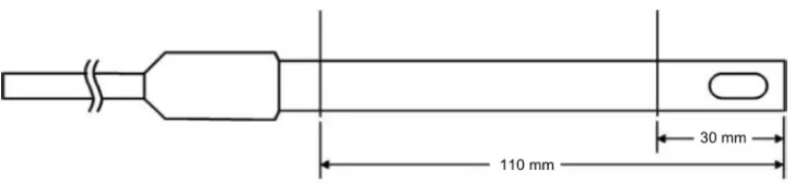
The measuring cell can either be stored dry or in water. After dry storage wetting time will be prolonged slightly. If changing over from one liquid to another with conductivities varying widely make sure to properly rinse and shake dry measuring cell.
If conductivity measured is much higher or lower than expected this may be due to the electrode being soiled with non-conducting or conducting foreign materials. The measuring cell has to be cleaned with a watery soap solution. When measuring media with low conductivities the electrode has to be stirred sufficiently.![]() NOTE
NOTE
Measuring cells must never come into contact with water-repellent materials such as oil or silicone.
Conductivity measurement
The conductivity measurement is a comparatively uncomplicated measurement. The standard electrodes are stable for correct use for a long time and can be calibrated over the gradient correction.
Operation and maintenance
Operating and maintenance notices
![]() NOTE
NOTE
The product and conductivity measuring cell must be handled with care and used inaccordance with the technical data. Do not throw or strike.![]() NOTE
NOTE
If the product is stored at a temperature above 50 °C, or is not used for an extended period of time, the batteries must be removed. Leaks from the batteries are avoided as a result.
The device is calibrated at the factory with the permanently connected conductivity measuring cell. The highest system precision can be achieved in this manner. If desired, a gradient correction can be carried out for the product in order to further optimize the accuracy in a narrow range. This is only necessary for normal use. See Adjustment of the measuring input.
Battery
5.2.1 Battery indicator
If the empty frame in the battery display blinks, the batteries are depleted and must be replaced. However, the device will still operate for a certain length of time.
If the BAT display text appears in the main display, the battery voltage is no longer adequate for the operation of the product. The battery is fully depleted.
5.2.2 Changing battery![]() DANGER
DANGER
The danger of explosion!
Using damaged or unsuitable batteries can generate heat, which can cause the batteries to crack and possibly explode!
Only use high-quality and suitable alkaline batteries!![]() CAUTION
CAUTION
Damage!
If the batteries have different charge levels, leaks and thus damage to the product can occur.
– Use new, high-quality batteries!
– Do not use different types of batteries!
– Remove depleted batteries and dispose of them at a suitable collection point.![]() NOTE
NOTE
This symbol indicates processes, which can have a direct influence on the operation or can trigger an unforeseen reaction in case of non-observance.![]() NOTE
NOTE
Read the following handling instructions before replacing batteries and follow them step by step.
If disregarded, the product could be damaged or the protection from moisture could be diminished.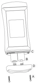
- Unscrews the Phillips screws (A)and remove the cover.
- Carefully replace the two Mignon AA batteries (B). Ensure that the polarity is correct! It must be possible to insert the batteries in the correct position without using force.
- The O-ring (C) must be undamaged, clean, and positioned at the intended depth. In order to facilitate assembly and avoid damage, a suitable grease can be applied.
- Fit the cover evenly. The O-ring must remain at the intended depth!
- Tighten the Phillips screws (A).
Operation
- Press the Function key for 2 seconds to open the Configuration menu.
 appears in the display. Release the Function key.
| Parameter | Values | Meaning |
|
 Input
Input
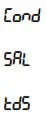 | Measured variable – conductivity |
| Measured variable – salt content / salinity | |
| Measured variable – total dissolved solids |
![]() Factor for TDS
Factor for TDS
| The conversion factor for TDS measurement |
![]() Temperature compensation
Temperature compensation
 | Do not compensate conductivity measurement |
| Non-linear function for natural water in accordance with EN 27888 (ISO 7888) Groundwater, surface water or drinking water |
Reference temperature for temperature compensation![]()
| 25 °C | Reference temperature 25 °C or 77 °F |
| 20 °C | Reference temperature 20 °C or 68 °F |
![]() Shut-off time
Shut-off time
| No automatic shut-off | |
| Automatic shut-off after a selected time in minutes, during which no buttons have been pressed |
![]() Backlight
Backlight
| Backlight deactivated | |
| Automatic shut-off of the backlight after a selected time in seconds, during which no buttons have been pressed | |
| No automatic shut off of the backlight |
![]() Display unit
Display unit
| °C | Temperature display in °C |
| °F | Temperature display in °F |
![]() Factory settings
Factory settings
| NO | Use current configuration |
| YES | Reset product to factory settings. in the display |
Adjustment of the measuring input
The temperature input can be adjusted with the zero point correction and the gradient correction. If an adjustment is made, you change the pre-adjusted factory settings. This is signaled with the ![]() display text when the product is switched on.
display text when the product is switched on.
- The product is switched off
- Press and hold the Down button.
- Press the On/Off button to switch on the product and open the Configuration menu. Release the Down button. The display shows the first parameter.
Zero point correction of the temperature![]()
| No zero point correction | |
| Zero-point correction in °C. and/or at °F -9.00 .. 9.00 |
![]() Gradient correction of the temperature
Gradient correction of the temperature
| No gradient correction | |
| Gradient correction in % |
![]() Gradient correction for the conductivity value
Gradient correction for the conductivity value
| No gradient correction | |
| Multiplier for the gradient correction |
Formula:
| Zero-point correction | Displayed value = measured value |
| Gradient correction °C: | Display = (measured value |
| Gradient correction °F: | Display = (meas. value |
| Gradient correction γ: | Display = measured value |
Error and system messages
| Display | Meaning | Possible causes | Remedy |
| —- | Range switching or measured value unstable | Measuring cell defect | Wait for the transient effect of the controller |
| Measurement far outside of the measuring range | Contamination or air bubbles | Measurement leaves the permissible range Send in for repair | |
(, , ) | Sensor cable defect | Cable breakage | Send in for repair |
| Sensor or probe defect | Defective sensor or probe | Send in for repair | |
| Measuring range exceeded or undercut | Measurement outside of the measuring range | ||
| No display, unclear characters or no response when buttons are pressed | Battery depleted | Battery depleted | Replace battery |
| System error | Error in the product | Send in for repair | |
| Product is defective | Product is defective | ||
| Battery depleted | Battery depleted | Replace battery | |
| Measuring range exceeded | Measurement too high Measuring cell defect | Stay within the allowable measurement range Check the measuring cell Send in for repair | |
| The measuring range is undercut | Measurement too low Measuring cell defect | Stay within the allowable measurement range Check the measuring cell Send in for repair | |
| System error | Error in the product | Switch product on/off Replace batteries Send in for repair |
Technical data
| Measuring range | Conductivity | 0 .. 2000 S/cm 0.00 .. 20.00 mS/cm 0.0 .. 100.0 mS/cm |
| Specific re- distance Salinity TDS | – 0.0 .. 50.0 g/kg 0 .. 2000 mg/ | |
| Temperature | -5.0 .. +105.0 °C (23.0 .. +221.0 °F) — the conductivity measuring cells can be exposed temporarily to temperatures of up to 100 °C and permanently to temperatures of up to 80 °C. | |
| Accuracy Measuring cycle | Conductivity Temperature | ± 0.5 % of measured value ± 0.5 % FS ± 0.3 °C approx. 10 measurements per second Updating of the display approx. 2 times per second |
| Display Additional functions | 3-line segment LCD, additional symbols, illuminated (adjustable white, permanent illumination) Min/Max/Hold | |
| Adjustment Housing | Offset and gradient correction – temperature, Gradient correction – conductivity Break-proof ABS housing | |
| Protection rating | IP65 / IP67 | |
| Dimensions L’W’H [mm] and weight | 108 * 54 * 28 mm without measuring cell or kink protection 180 g, incl. battery and measuring cell | |
| Operating conditions | -20 to 50 °C; 0 to 95 %RH (temporarily 100 %RH) | |
| Storage temperature | -20 to 70 °C | |
| Power supply | 2’AA battery (included in the scope of delivery) | |
| Current requirement/ battery life Battery indicator | approx. 2.2 mA, approx. 3.5 mA with lighting Service life > 1000 hours with alkaline batteries (without backlighting) 4-stage battery status indicator, Replacement indicator for depleted batteries: “BAT” | |
| Auto-power-OFF function | The device switches off automatically if this is activated | |
| Directives and standards | The devices conform to the following Directives of the Council for the harmonization of legal regulations of the Member States: 2014/30/EU EMC Directive 2011/65/EU RoHS Applied harmonized standards: EN 61326-1:2013 Emission limits: Class B Immunity according to Table 2 Additional errors: < 1 % FS EN 50581:2012 The device is intended for mobile use and/or stationary operation in the scope of the specified operating conditions without further limitations. | |
Service
Manufacturer
If you have any questions, please do not hesitate to contact us:
Contact
RS Components Limited
Birchington Road
Corby
Northamptonshire
NN17 9RS
WEE/GF0002ZR