![]()
Bante 520 Portable Conductivity Meter
USER MANUAL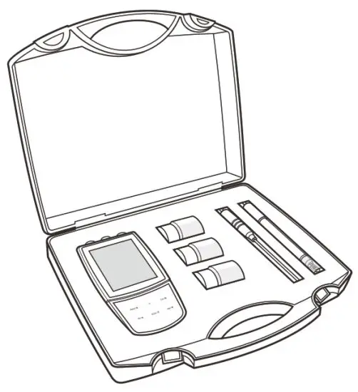
Bante Instruments Inc.
Introduction
Thank you for selecting the 520 portable conductivity meter. This user manual provides a step-by-step guide to help you operate the meter, please carefully read the following instructions before use. Any use outside of these instructions may invalidate your warranty and cause permanent damage to the meter.
Environmental Conditions
Before unpacking, ensure that current environmental conditions meet the following requirements.
- Relative humidity is less than 80%
- Ambient temperature between 0° C (32° F) and 50° C (122° F)
- No potential electromagnetic interference
- No corrosive gas exists
Packing List
The following list describes all components of the meter. If any items are missing or damaged, contact the supplier immediately.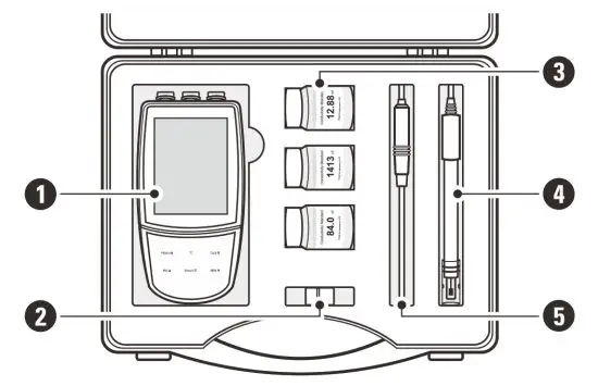
- 520 meter
- Electrode clip
- Standard solutions
- Conductivity electrode
- Temperature probe
Meter Overview
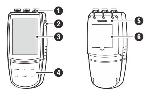
| 1. Sensor connections 2. Slot for electrode clip 3. Display | 4. Membrane keypad 5. Slot for hand strap 6. Battery compartment |
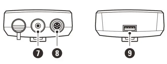 7. Socket for temperature probe (3.5 mm jack)
8 . Socket for conductivity electrode (6-pin DIN)
9. USB-A interface to the computer or power adapter
Display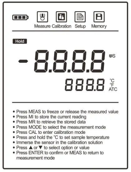
| Icon | Description |
 | Indicates that the meter is in the measurement mode |
 | Indicates that the meter is in the calibration mode |
 | Indicates that the meter is in the setup mode |
 | Indicates that you are viewing the stored readings or a reading is stored into the memory |
| When the battery voltage falls below the minimum power requirements, the icon automatically disappears | |
| Indicates that the measurement is locked | |
| ATC | Indicates that the automatic temperature compensation is enabled |
Keypad
| Key | Function |
| • Switch the meter on or off • Lock or unlock the measurement • Exit the calibration, settings, data logs and return to the measurement mode | |
| • Set the temperature | |
| • Start calibration • Press and hold the key to enter the setup menu | |
| • Store current reading to memory • Increase value or scroll up through a list of options | |
| • View the data log or calibration log • Decrease value or scroll down through a list of options | |
| • Confirm the calibration or displayed option • Press and hold the key to switch the backlight on or off |
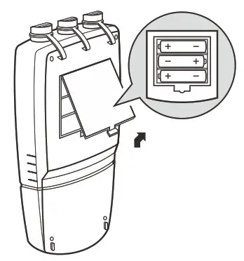
Installing the Batteries
- Remove the battery compartment cover from the backside of the meter, insert three AA batteries into the battery compartment, note polarity.

- Replace the battery compartment cover to its original position, push the limiter until it locks.
![]() The meter allows using the 5V DC power adapter (order code: DCPA5V) or the USB port on computer as a power supply.
The meter allows using the 5V DC power adapter (order code: DCPA5V) or the USB port on computer as a power supply.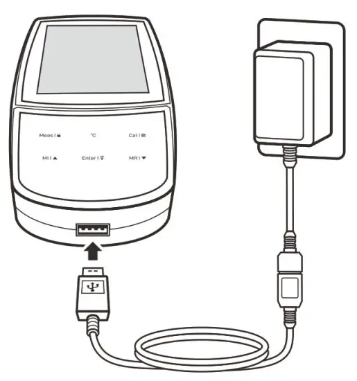
![]() Note, take out the batteries before connecting an external power supply.
Note, take out the batteries before connecting an external power supply.
Installing the Electrode Clip
The electrode clip is designed for mounting a sensor, but it is not a necessary component for meter. If you want to install this accessory, insert the electrode clip into the slot on the right of the meter.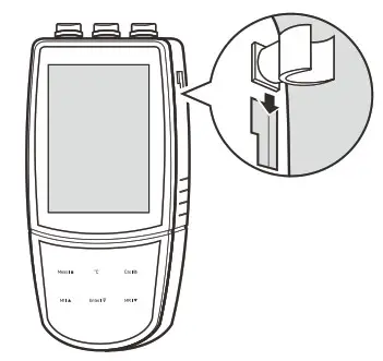
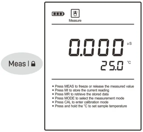
Switching the Meter On and Off
- Press the Meas key and release to switch on the meter.
- Press and hold the Meas key to switch off the meter.

Meter Setup
The 520 meter contains 10 menu items in setup menu. The following table describes the functions of each menu item.
| Menu Item | Option and Description |
| Cell Constant Set the cell constant to match connected electrode. | |
1.0 K = 0.1 | |
1 K = 1 (default) | |
10 K = 10 | |
| Calibration Points Set the number of calibration points. | |
1 1 point | |
2 2 points | |
3 3 points (default) | |
| Temperature Coefficient Set the temperature correction method and coefficient. | |
| Pure Water Compensation If enabled, the pure water compensation coefficient will be applied automatically for ultra-pure water measurements. | |
| Reference Temperature Set the normalization temperature for measurement, the readings will automatically compensate to the selected temperature during measurement. | |
25°C 25° C (default) | |
20°C 20°C | |
| Measurement Unit Set the default temperature unit. | |
°C Degrees Celsius (default) | |
°F Degrees Fahrenheit | |
| Auto-Hold If enabled, the meter will automatically sense and lock the measurement endpoint. | |
| Auto-Power Off If enabled, the meter will automatically switch off if no key is pressed within 30 minutes. | |
CLr | Clear Stored Data Delete all data logs in the memory. |
| Factory Reset Reset the meter to factory default settings. Note, the meter must be recalibrated. | |
![]() The meter contains two temperature correction methods. The linear temperature correction is appropriate for most samples. If the current samples belong to the natural water (e.g., natural ground, well, or surface waters), using the non-linear correction is necessary.
The meter contains two temperature correction methods. The linear temperature correction is appropriate for most samples. If the current samples belong to the natural water (e.g., natural ground, well, or surface waters), using the non-linear correction is necessary.
![]() Note, the non-linear correction can only be performed at temperature range from 0° C to 36° C (32° F to 96° F). If the temperature value is out of above range, the display will always show —-.
Note, the non-linear correction can only be performed at temperature range from 0° C to 36° C (32° F to 96° F). If the temperature value is out of above range, the display will always show —-.
Setting the Default Option
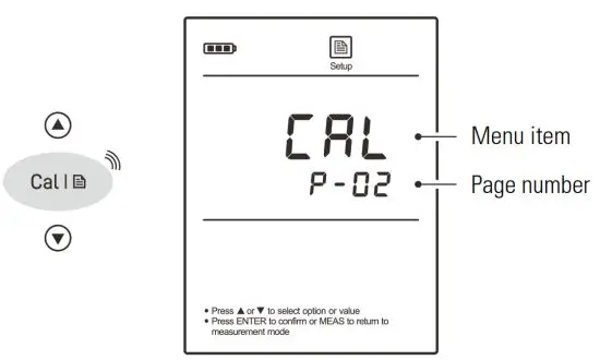
- In the measurement mode, press and hold the
 key to enter the setup menu.
 - Press the
 /
/  key to select a menu item.
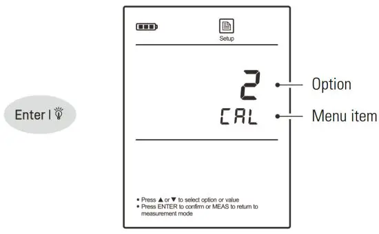
- Press the Enter key, the meter shows the current option.

- Press the / key to select a desired option.
- Press the Enter key to save and return to the measurement mode.

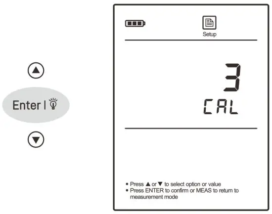
![]() To exit the setup menu without saving changes, press the Meas key.
To exit the setup menu without saving changes, press the Meas key.
Connecting the Electrode
Take out the conductivity electrode from the carrying case. Insert 6-pin connector into the connector socket on meter, ensure the connector is fully seated.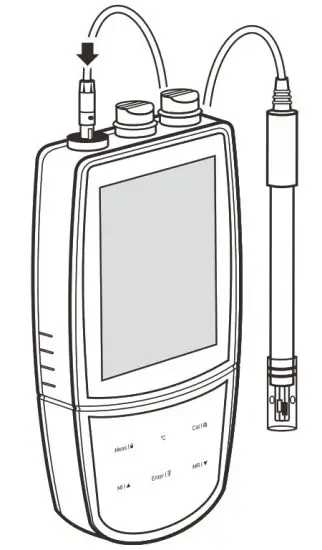
After connection is completed, DO NOT pull on the sensor cable. Always make sure that the connector is clean and dry.
Temperature Compensation
The temperature compensation has a large effect on the conductivity measurement. If enabled, the meter will use the measured conductivity and temperature readings to calculate the results and automatically compensate to the selected reference temperature. If the temperature coefficient is set to 0, the temperature compensation will be disabled and the meter only shows the actual conductivity at the measured temperature.
Automatic Temperature Compensation
Connect the temperature probe to meter, the ATC icon appears on the display, the meter is now switched to the automatic temperature compensation mode.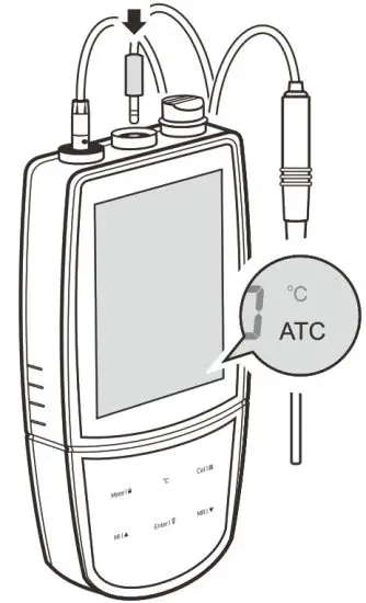
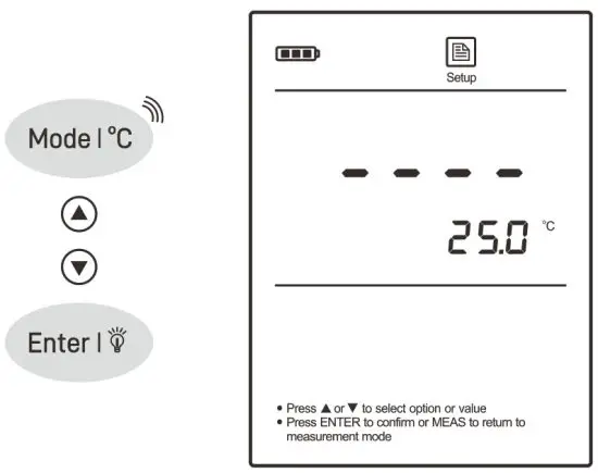
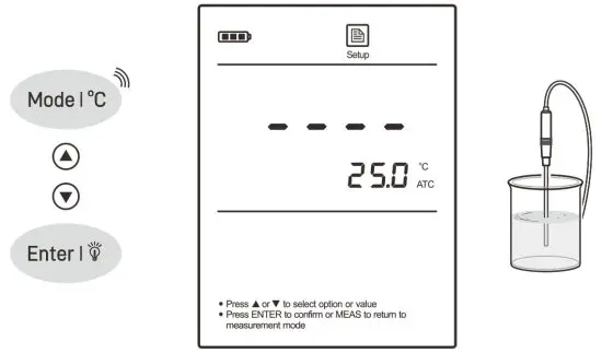
Manual Temperature Compensation
If the meter does not detect a temperature probe, the degrees Celsius icon (°C) will show on the display indicating the meter is switched to the manual temperature compensation mode. To set the temperature value follow the steps below.
- Press and hold the °C key to enter the temperature setting.
- Press the / key to modify the temperature value.
- Press the Enter key to save.
![]() Press and hold the
Press and hold the ![]() /
/ ![]() key will make the value change faster.
key will make the value change faster.
Selecting a Conductivity Electrode
The 520 meter is capable of using the three types of conductivity electrodes. Before the calibration and measurement, ensure that you have selected a suitable electrode according to the anticipated sample conductivity. The following table lists the selectable electrode and its effective measurement ranges.
| Electrode | Measurement Range | Cell Constant |
| CON-0.1 | 0.5 to 100 µ S/cm | K = 0.1 |
| CON-1 | 10 µ S/cm to 20 mS/cm | K = 1 |
| CON-10 | 100 µ S/cm to 200 mS/cm | K = 10 |
Conductivity Calibration
The meter allows up to 3 points calibration in the conductivity mode. Before beginning the calibration, ensure that selected cell constant (K = 0.1, 1, 10) matches connected electrode. For better accuracy, we recommend to perform 3 points calibration or select a standard solution closest to the sample conductivity you are measuring. The meter will automatically detect the standard solution and prompt the user to perform the calibration. If you have changed the electrode, the meter must be recalibrated. The following table shows the default standard solution for each measurement range.
| Measurement Range | Default Standard Solution |
| 0 to 20 µ S/cm | 10 µ S/cm |
| 20 to 200 µ S/cm | 84 µ S/cm |
| 200 to 2000 µ S/cm | 1413 µ S/cm |
| 2 to 20 mS/cm | 12.88 mS/cm |
| 20 to 200 mS/cm | 111.8 mS/cm |
Single Point Calibration
- Ensure that you have selected 1 point calibration in the setup menu.
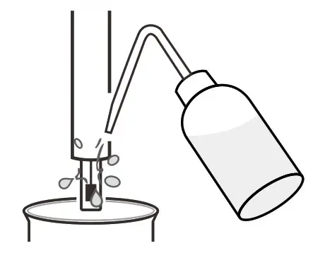
- Rinse the electrode with distilled water, then rinse with a small amount of standard solution.

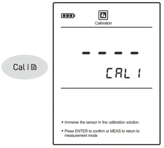
- Press the Cal key, the display shows —-/CAL1, the meter waits for recognizing the standard solution.

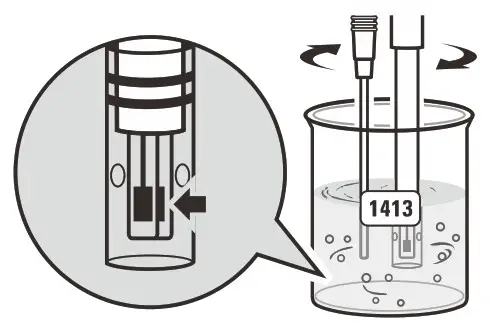
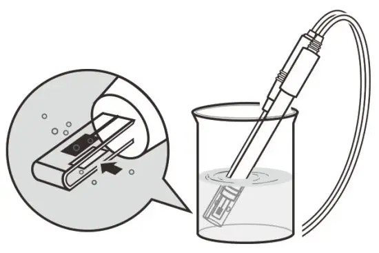
- Place the electrode (and temperature probe) into the standard solution, stir gently to remove air bubbles trapped in the slot of the sensor.
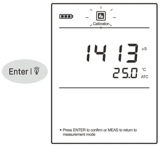
 The meter will automatically show the calibration standard (e.g.,1413 µ S/cm).
- Press the Enter key, the Calibration icon begins flashing.

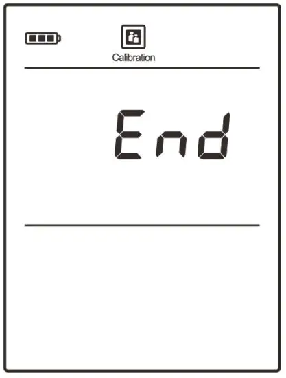
- When the reading has stabilized, the meter will show and
Endreturn to the measurement mode.
 The meter will automatically show the calibration standard (e.g.,1413 µ S/cm).
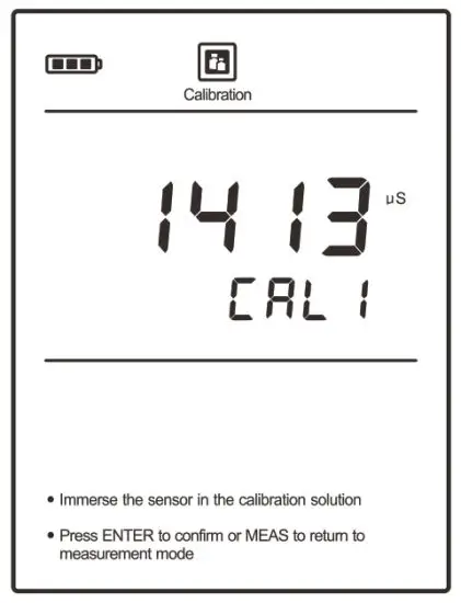
Multipoint Calibration
- Ensure that you have selected 2 or 3 points calibration in the setup menu.
- When the first calibration point is completed, the display will show —-/CAL2. The meter prompts you to continue with second point calibration.
- Repeat steps 1.2, 1.4 and 1.5 above until the meter shows
End. Calibration is completed.
![]() To exit the calibration without saving changes, press the Meas key.
To exit the calibration without saving changes, press the Meas key.
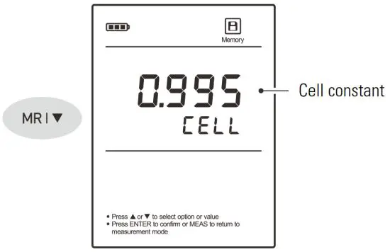
Viewing the Calibration Log
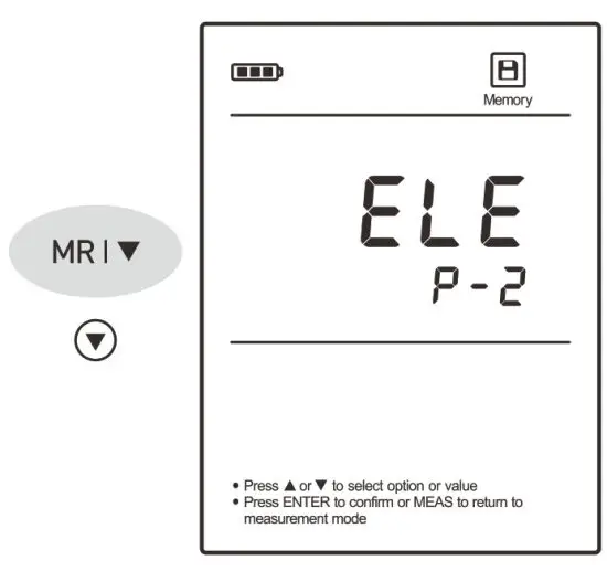
- Press the MR key in the measurement mode and press the key until the meter shows ELE/P-2 (Electrode/Page 2).

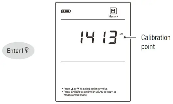
- Press the Enter key, the meter shows the calibration point 1.

- Press the key to view the calibration factor of the calibration point 1 (e.g., 0.995).

- Press the key to view the next data set.
- To exit the calibration log, press the Meas key
![]() If the meter is not calibrated with standard solution, the display will show —- only.
If the meter is not calibrated with standard solution, the display will show —- only.
Temperature Calibration
The 520 meter is supplied with a temperature probe for measurement and temperature compensation. If the measured temperature reading differs from that of an accurate thermometer, the probe needs to be calibrated.
- Connect the temperature probe to the meter and place into a solution with a known accurate temperature.
- Press and hold the °C key to enter the temperature setting.
- Press the / key to modify the temperature value.
- Press the Enter key to save.

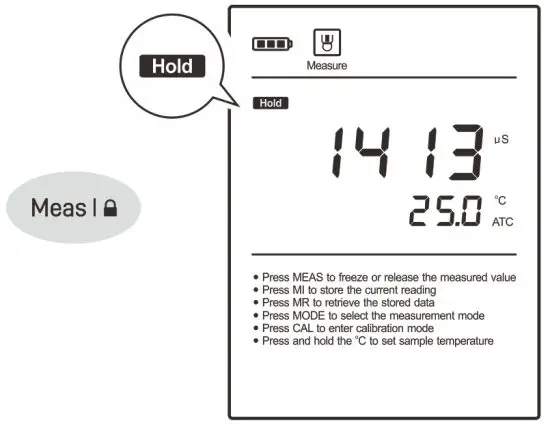
Measurement
- Rinse the conductivity electrode with distilled water. Place the electrode (and temperature probe) into the sample solution and stir gently. Ensure that no air bubbles on the sensor surface.

- If the Auto-Hold option in the setup menu is enabled, the meter will automatically lock the measurement endpoint and show HOLD icon. Press the Meas key to resume measuring. If the option is disabled, the meter will continuously measure and update the readings.

- Wait for the measurement to stabilize and record the reading.
- When all of the samples have been measured, rinse the electrode with distilled water.
![]() If the meter shows —- indicating the measurement exceeds the range, replace a conductivity electrode that is appropriate for the conductivity range of the sample solution you are measuring.
If the meter shows —- indicating the measurement exceeds the range, replace a conductivity electrode that is appropriate for the conductivity range of the sample solution you are measuring.
Data Management
The 520 meter is capable of storing and recalling up to 100 data sets.
Storing a Measurement Result
In the measurement process, press the MI key to store the reading into the memory, the Memory icon appears on the display.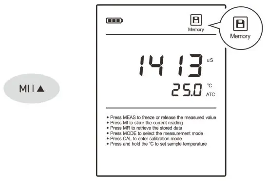 Viewing the Data Logs
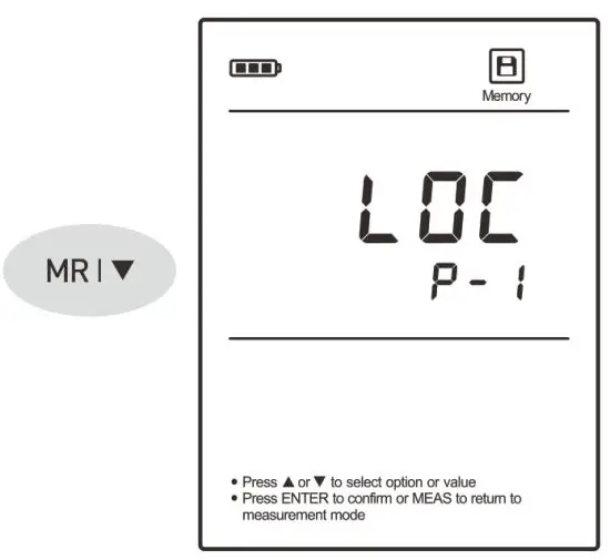
- Press the MR key in the measurement mode, the meter shows
 (Log/Page 1).
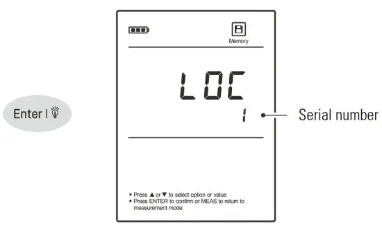
- Press the Enter key, the meter shows the serial number of the stored data.

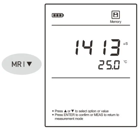
- Press the key to view the stored data.
- Press the key to view the next data set.
- To exit the data log, press the Meas key.
![]() If the meter does not store any reading, the display will show —- only.
If the meter does not store any reading, the display will show —- only.
Clearing the Data Logs
If the memory is full, the meter will automatically show FULL when the MI key is pressed. To delete the data logs, please follow the steps below.
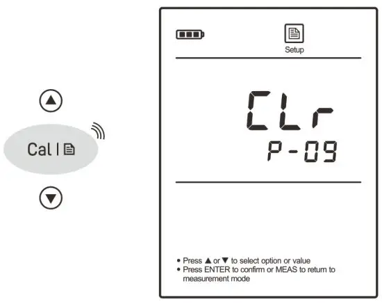
- Press and hold the key to enter the setup menu.
- Press the key until the meter shows
CLr/P-09.
- Press the Enter key, the meter shows
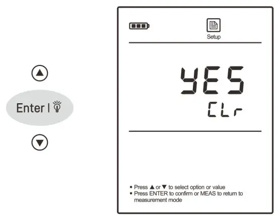
no/CLr - Press the key to select the
YE5/CLr
- Press the Enter key to confirm.
Communication
The 520 meter can transfer the data to a computer or import the data to Excel by a DAS software. You are able to download this software from our official website. Before installation, make sure that the Windows 10 operating system has been installed on your computer and you have a USB-B2303 data cable.
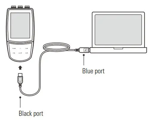
Receiving the Data
- Connect the black port of the data cable to meter and the blue port to computer.

- Click the DAS _ ECO _ Series icon, the system automatically scans an available communication port and shows a message box “Found a port on your computer”.
- Click the OK, the application starts.
- Click the Connect, the screen shows “Port is connected”.
- Click the OK, then click the Receive, the stored data will transfer to computer automatically.
![]() If your computer can not find a communication port, click the “PL2303 _Prolific_DriverInstaller_v1190.exe” to update the drive program.
If your computer can not find a communication port, click the “PL2303 _Prolific_DriverInstaller_v1190.exe” to update the drive program.
Creating an Excel File
When transfer is completed, click the Save as Excel, the readings in data sheet will automatically convert to Excel file.![]() Note, once the software is closed, all received data will be lost and can not be recovered.
Note, once the software is closed, all received data will be lost and can not be recovered.
Electrode Maintenance
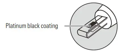
- Rinse the electrode thoroughly with distilled water after use.
- Do not touch the platinum black coating on the sensor surface and always keep it clean.

- If there is a build-up of solids inside the sensor, remove carefully, then recalibrate the electrode.
- If you do not use the electrode for long periods, wipe clean with a lint-free tissue and store the electrode in a dry and cool area.
- If your electrode is model CON-10, store the electrode with tap water. This sensor needs to be kept wet always.
Appendix
Preparation of Conductivity Standard Solutions
- Place the analytical grade potassium chloride (KCl) in a beaker and dry in an oven for about 3 hours at 105° C (221° F), then cool to room temperature.
- Add the reagent to a 1 liter volumetric flask according to the instructions in table below.
Conductivity Standard Reagent Weight 84 µ S/cm KCl 42.35 mg 1413 µ S/cm KCl 745.5 mg 12.88 mS/cm KCl 7.45 g 111.8 mS/cm KCl 74.5 g - Fill the distilled water to the mark, mix the solution until the reagent is completely dissolved.
Calculating the Cell Constant
- Refer to the Meter Setup section to reset the meter.
- Place the electrode into a standard solution and record the reading.
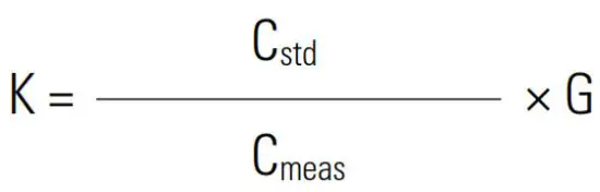
- Calculate the cell constant using the following formula.
 Where:
K = Cell constant
Cstd = Value of conductivity standard solution
Cmeas = Measured value
G = Raw cell constant (0.1, 1 or 10)
 Where:
Calculating the Temperature Coefficient
- Do not connect the temperature probe to meter.
- Press and hold the °C key to enter the temperature setting.
- Press the / key to set the temperature to 25° C and press the Enter key to confirm.
- Place the conductivity electrode into the sample solution, record the temperature value TA and conductivity value CTA.
- Condition the sample solution and electrode to a temperature TB that is about 5° C to 10° C different from TA. Record the conductivity value CTB.
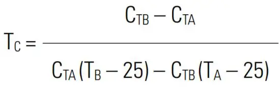
- Calculate the temperature coefficient using the formula below.
 Where:
TC = Temperature coefficient
CTA = Conductivity at temperature A
CTB = Conductivity at temperature B
TA = Temperature A
TB = Temperature B
 Where:
Optional Accessories
| Conductivity Electrodes | |
| Order Code | Description |
| CON-0.1 | For measuring the pure water |
| CON-1 | For general purpose applications |
| CON-10 | For measuring the high conductivity liquids |
| Temperature Probe | |
| Order Code | Description |
| TP-10K | 3.5 mm jack plug, 1 m (3.3 ft) cable |
| Solutions | |
| Order Code | Description |
| ECCS-84 | Conductivity standard solution 84 µ S/cm, 480 ml |
| ECCS-1413 | Conductivity standard solution 1413 µ S/cm, 480 ml |
| ECCS-1288 | Conductivity standard solution 12.88 mS/cm, 480 ml |
| ECCS-1118 | Conductivity standard solution 111.8 mS/cm, 480 ml |
| Communication and Power Supply | |
| Order Code | Description |
| USB-2303A | USB connector A to A, 1 m (3.3 ft) cable |
| DCPA-5V | 5V DC power adapter, european standard plug |
Meter Specifications
| Model | Bante 520 |
| Conductivity | |
| Range | 0.01 µ S/cm to 200.0 mS/cm |
| Resolution | 0.001, 0.01, 0.1, 1 |
| Accuracy | ± 0.5% F.S. |
| Calibration Points | 1 to 3 points |
| Calibration Solutions | 10 µ S/cm, 84 µ S/cm, 1413 µ S/cm, 12.88 mS/cm, 111.8 mS/cm |
| Temperature Compensation | 0 to 100° C (32 to 212° F), manual or automatic |
| Temperature Coefficient | Linear (0.0 to 10.0%/° C), non-linear or pure water |
| Reference Temperature | 20 or 25° C |
| Cell Constant | K = 0.1, 1, 10 |
| Temperature | |
| Range | 0 to 105° C (32 to 221° F) |
| Resolution | 0.1° C (0.1° F) |
| Accuracy | ± 0.5° C (± 0.9° F) |
| Calibration Point | 1 point |
| Other Specifications | |
| Memory | 100 data sets |
| Communication Interface | USB-A |
| Operating Temperature | 0 to 50° C (32 to 122° F) |
| Storage Temperature | 0 to 60° C (32 to 140° F) |
| Relative Humidity | < 80% (non-condensing) |
| Display | LCD, 80 × 60 mm (3.15 × 2.36 in.) |
| Power Requirements | 3 × 1.5V AA alkaline batteries or 5V DC power adapter |
| Auto-Off | 30 minutes after last key pressed |
| Dimensions | 170 (L) × 85 (W) × 30 (H) mm, (6.69 × 3.35 × 1.18 in.) |
| Weight | 300 g (10.5 oz.) |
Troubleshooting
| Fault | Cause and Corrective Action |
| —– | Electrode dried out. Soak the conductivity electrode in tap water for about 10 minutes. |
| Measurement exceeded the maximum range. Check the electrode and sample. If non-linear correction is enabled, make sure that the sample temperature between 0 and 36° C. | |
| Drifting erratic readings | Check whether electrode is contaminated, clogged or broken. |
Err | Electrode is broken. Replace the conductivity electrode. |
| Keypad is not working | Replace the batteries. |
Disposal
This product is required to comply with the European Union’s Waste Electrical and Electronic Equipment (WEEE) Directive 2002/96/EC and may not be disposed of in domestic waste. Please dispose of product in accordance with local regulations at the collecting point specified for electrical and electronic equipment.

Warranty
The warranty period for meter is one year from the date of shipment. Above warranty does not cover the electrode and electrolyte solution. Out of warranty products will be repaired on a charged basis. The warranty on your meter shall not apply to defects resulting from:
- Improper or inadequate maintenance by customer
- Unauthorized modification or misuse
- Operation outside of the environment specifications of the products.
For more information, please contact the supplier.
![]()
Office: 4715 Castlewood St., Sugar land, TX 77479, USA
Tel: (+1) 346-762-7358
E-mail: [email protected]
Factory: A10, No.2066, Laifang Rd., Shanghai 201615, China
Tel: (+86) 21-6404-1598
E-mail: [email protected]![]() www.bante-china.com
www.bante-china.com
 http://bante-china.com/enHome/
The information in this document is subject to change without notice.
Copyright © Bante Instruments Inc, 2022. All rights reserved.


