![]() BI-650 Industrial Conductivity Controller
BI-650 Industrial Conductivity Controller
USER MANUAL
Bante Instruments Inc.
Overview
Introduction
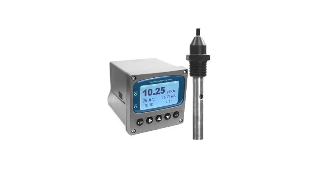
Thank you for selecting the BI-650 industrial conductivity controller. This user manual provides a step-by-step guide to help you operate. the meter, please carefully read the following instructions before use.
Environmental Conditions
Before the installation, ensure that current environmental conditions meet the following requirements.
- Relative humidity is less than 80%
- Ambient temperature between 5°C (41°F) and 50° C (122° F)
- No potential electromagnetic interference
- No corrosive gas exists
Packing List
The following list describes all components of the meter. If any itemare missing or damaged, contact the supplier immediately.
BI-650 conductivity controller
IE-50MT industrial conductivity electrode
Conductivity standard solution 1413 µ S/cm
Installation
Safety Warning
- BI-650 meter shall be installed and operated only in the manner specified in this user manual.
- Only skilled, trained or authorized person should carry out installation, setup and operation of meter.
 The rear panel of meter has two screw terminals for connecting the 24V DC power supply. Make sure to cut off the main power before installation and maintenance.
- Once the power supply cable is connected to the meter, DO NOT touch any screw terminals.
Installing the Meter
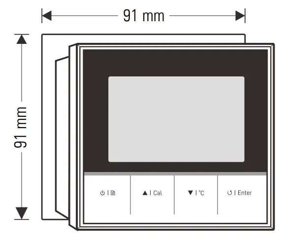
1.1 Cut out a square hole approximately 91 × 91 mm (3.58 × 1.58 in.) in the mounting panel.
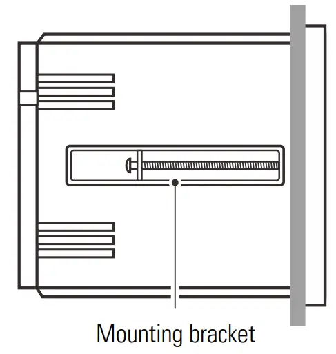
1.2 Remove the mounting bracket, place the meter into the square hole.
1.3 Replace the mounting bracket and push the meter forward until it is fully seated on the mounting plate.
Installing the Electrode
2.1 Wrap Teflon tape to the electrode body threads.
2.2 Insert the electrode into the mounting position and slowly turn clockwise until secure. Hand tighten the electrode to prevent liquid leakage.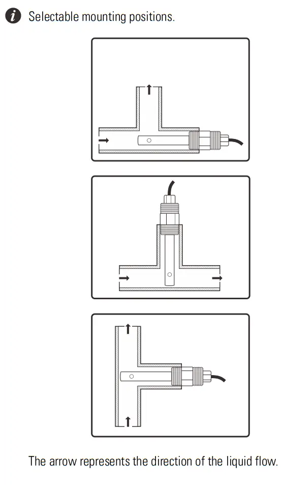
Connection
| No. | Terminal | Description |
| 1 | — | No connection |
| 2 | EC (+) | Conductivity/ TDS input |
| 3 | EC (−) | Conductivity/ TDS input |
| 4 | — | No connection |
| 5 | TC (−) | Temperature input (−) |
| 6 | TC (+) | Temperature input (+) |
| 7 | 485 (B) | RS485 signal output (B) |
| 8 | 485 (A) | RS485 signal output (A) |
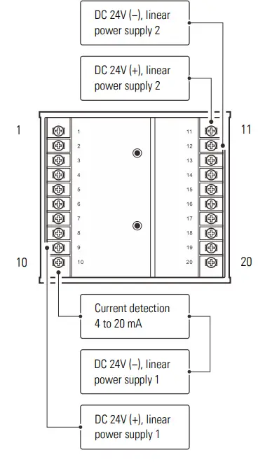
| 9 | DC 24 (+) | DC 24V (+), linear power supply 1 |
| 10 | DC 24 (−) | DC 24V (−), linear power supply 1 |
| 4 to 20 mA analog output | ||
| 11 | GND | Earth ground |
| 12 | DC 24 (+) | DC 24V (+), linear power supply 2 |
| 13 | DC 24 (−) | DC 24V (−), linear power supply 2 |
| 14 | NC2 | Relay resting position (NC2) |
| 15 | NO2 | Relay working position (NO2) |
| 16 | COM2 | Relay common (COM2) |
| 17 | NC1 | Relay resting position (NC1) |
| 18 | NO1 | Relay working position (NO1) |
| 19 | COM1 | Relay common (COM1) |
| 20 | — | No connection |
Meter Overview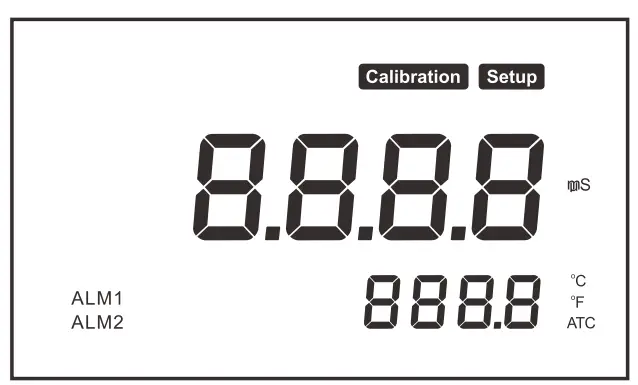 Display
| Icon | Description |
| Calibration | Indicates that the meter is in the calibration mode |
| Setup | Indicates that the meter is in the setup mode |
| ATC | Indicates that the automatic temperature compensation is enabled |
| ALM1 | Indicates the measurement exceeded the high limit |
| ALM2 | Indicates the measurement exceeded the low limit |
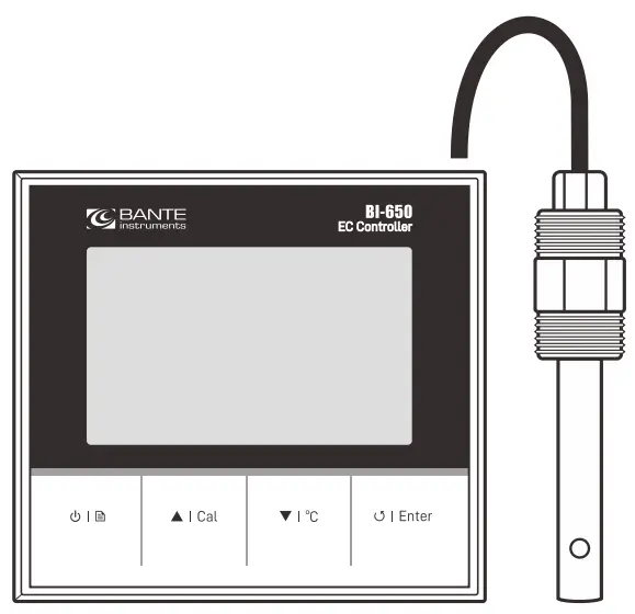
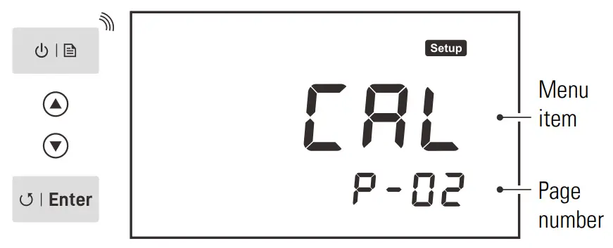
Keypad
| Key | Function |
| • Switch the meter on or off • Press and hold the key to enter the setup menu • Exit the calibration, settings and return to the measurement mode |
 | • Start calibration • Increase value or scroll up the menu items |
| • Set the temperature • Decrease value or scroll down the menu items | |
| • Toggle between the conductivity and TDS modes • Confirm the calibration, setting or displayed option |
Setup
Meter Setup
The BI-650 meter contains an integrated setup menu for customizing the displayed option to meet measurement requirement. The following table describes the functions of each menu item.
| Menu Item | Option and Description |
| Cell Constant Set the cell constant to match connected conductivity electrode. | |
1 K = 0.1, 1, 10 (default 1) | |
| Calibration Points Set the number of calibration points. | |
2 1 to 3 points (default 1 point) | |
| Temperature Coefficient Set the temperature coefficient for linear temperature compensation. | |
2.1 0.0 to 10.0%/°C (default 2.1) | |
| TDS Factor Set the default TDS conversion factor. | |
0.5 0.1 to 1.0 (default 0.5) | |
| Temperature Unit | |
ºC Degrees Celsius (default) | |
ºF Degrees Fahrenheit | |
| Low Alarm Limit | |
| Setting range: 0.02 µS/cm to 20.00 mS/cm (default 0.02 µS/cm) | |
| High Alarm Limit | |
| Setting range: 20.00 mS/cm to 0.02 µS/cm (default 1000 µS/cm) | |
| Hysteresis Value (Low) | |
| Setting range: 1% to 99% (default 10%) | |
| Hysteresis Value (High) | |
| Setting range: 1% to 99% (default 1%) | |
| Analog Output (Low) | |
| Setting range: 0.02 µS/cm to 20.00 mS/cm (default 0.02 µS/cm) |
| Analog Output (High) | |
| Setting range: 20.00 mS/cm to 0.02 µ S/cm (default 20.00 mS/cm) | |
| Factory Reset Reset the meter to factory default settings. Note, the meter must be recalibrated. | |
YES Enable | |
no Disable (default) |
 If the high or low alarm is enabled, the meter will be activated when the measurement exceeds specified limit. Note, this option can not enter the same values.
- If the hysteresis is enabled, the meter will prevent rapid contact switching when the measurement is fluctuating near the set point. For example, you have set the high alarm at 20 mS/cm and hysteresis value at 1%. When the measurement overshoots the 20.2 mS/cm, the meter will activate an external device. When the measurement drops to 19.8 mS/cm, the device will switch off.
- The default RS485 communication is 0.02 µ S/cm to 20.00 mS/cm corresponds to the 4.00 to 20.00 mA.
Setting a Default Option
- In the measurement mode, press and hold the
 key to enter the setup menu.
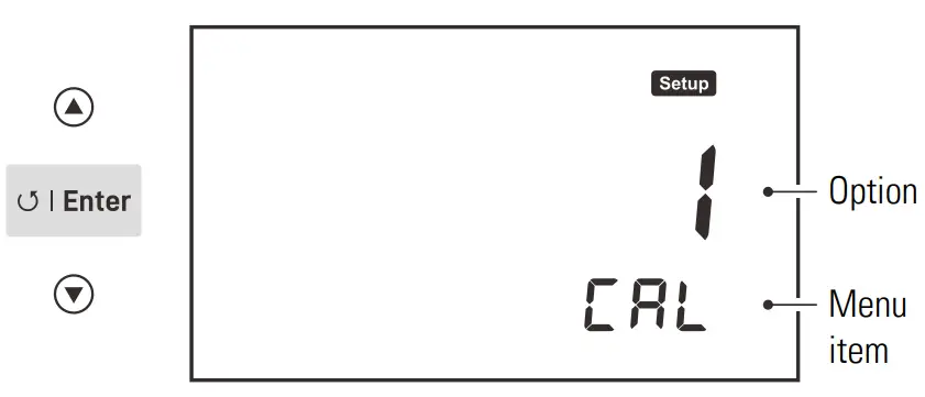
 - Press the ▲/ ▼ key to select a menu item, press the Enter key to confirm.

- Press the ▲ / ▼ key to select an option or set a value, press the Enter key to save.

To exit the setup menu without saving changes, press the![]() key.
key.
Calibration and Measurement
Temperature Compensation
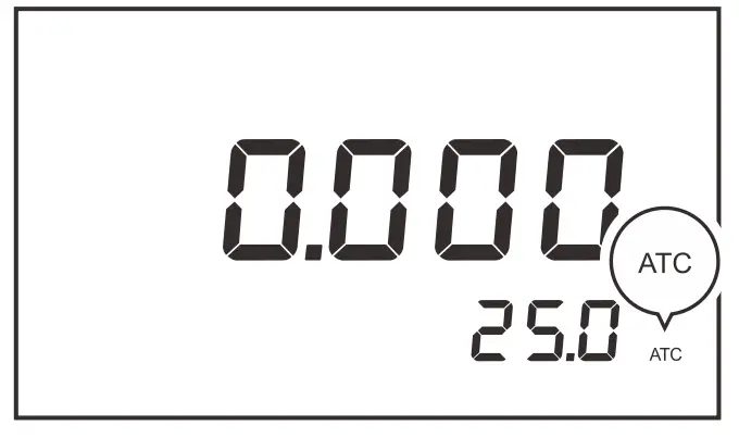
The BI-650 meter is supplied with an industrial conductivity electrode.When the wires of electrode are connected to the meter, the display.will show ATC icon immediately. The meter is now switched to the.automatic temperature compensation mode.
Temperature Calibration
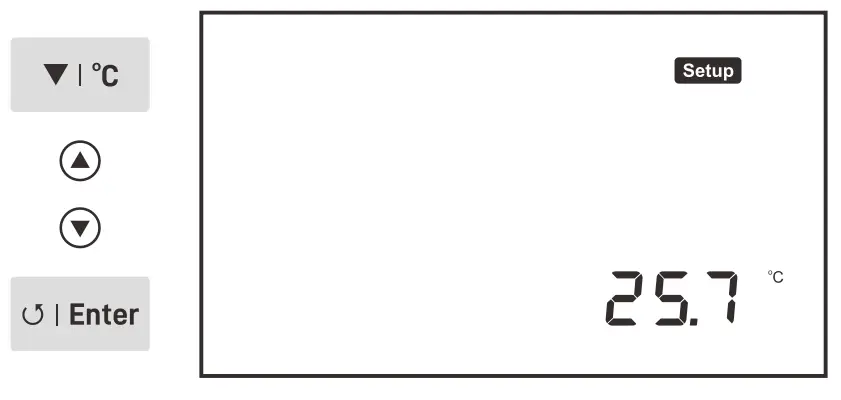
During the measurement, if the measured temperature reading differs from that of an accurate thermometer, the electrode needs to be calibrated.
- Place the electrode into a solution with a known accurate temperature.
- Press the °C key to enter the temperature setting.
- Press the ▲/ ▼key to modify the temperature value.
- Press the Enter key to save.
Selecting a Conductivity Electrode
The BI-650 meter is capable of using three types of electrodes. Beforethe calibration and measurement, ensure that you have selected a suitable electrode according to the anticipated sample conductivity. The following table lists the selectable electrode and its effective measurement ranges.
| Electrode | Measurement Range | Cell Constant |
| IE-50LT | 0.5 to 100 µS/cm | K = 0.1 |
| IE-50MT | 10 µS/cm to 20 mS/cm | K = 1 |
| IE-50HT | 100 µS/cm to 200 mS/cm | K = 10 |
Conductivity Calibration
The BI-650 meter allows 1 to 3 points conductivity calibration. For better accuracy, we recommend to perform 3 points calibration or select a standard solution closest to the sample conductivity you are measuring. The meter will automatically detect the standard solution and prompt the user to perform the calibration. The following table shows the
default standard solution for each measurement range.
| Measurement Range | Default Standard Solution |
| 20 to 200 µS/cm | 84 µS/cm |
| 200 to 2000 µS/cm | 1413 µS/cm |
| 2 to 20 mS/cm | 12.88 mS/cm |
| 20 to 200 mS/cm | 111.8 mS/cm |
Single Point Calibration
Ensure that you have selected 1 point calibration in the setup menu. 1.1 Press the Cal key, the display shows — /CAL 1 , the meter waits for recognizing the standard solution.
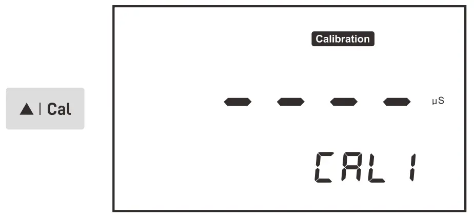
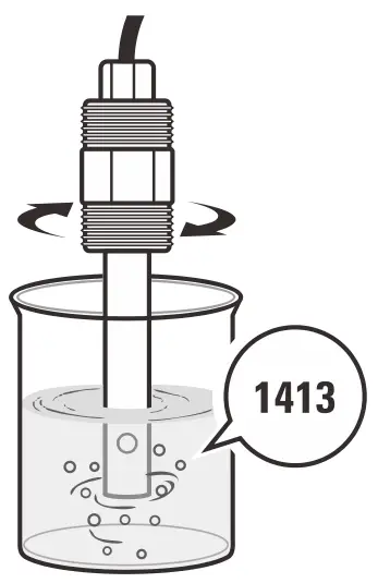
1.2 Rinse the conductivity electrode with distilled water, then rinse with a small amount of standard solution.
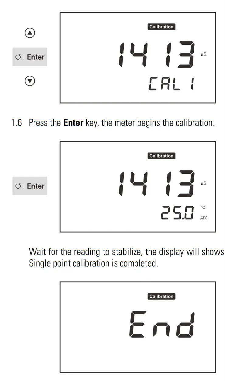
1.3 Place the electrode into the standard solution, the meter will automatically show the calibration standard (e.g., 1413 µ S/cm).
1.4 Press the Enter key, the default calibration value begins flashing.
1.5 Press the ▲/ ▼key to set the calibration value, press the Enter key to confirm and move to next digit. When the setting is completed, ensure that displayed value matches your calibration standard.
Multipoint Calibration
Ensure that you have selected 2 or 3 points calibration in the setup menu.
2.1 When the first calibration point is completed, the display will show —/CAL 2 Calibration is completed.
2.2 Repeat steps 1.2 through 1.6 above until the meter shows End Calibration is completed.
- Performing the conductivity calibration will simultaneously calibrate the corresponding TDS value.
- To exit the calibration without saving changes, press the
 key.
key.
Measurement
- Press the
 key to select the conductivity (
COnd) or TDS (Eds) mode. - Place the electrode into the sample. Wait for the measurement to stabilize.
Communication
The BI-650 meter uses a standard Modbus-RTU protocol. All of the data are character type (2 bytes). The response data ranges between -32767 to 32767, hexadecimal.
PC Command
| Definition | Length of Byte | Data |
| ID address | 1 | 0 × 02 |
| Command | 1 | 0 × 03 |
| Start address | 2 | 0 × 0001 |
| Data number | 2 | 0 × 0002 |
| CRC16 | 2 | 0 × 95F8 |
Meter Response
| Definition | Length of Byte | Data |
| ID address | 1 | 0 × 02 |
| Command | 1 | 0 × 03 |
| Data Length | 1 | 0 × 0002 |
| Data | N | 0 × 02 0 × BC |
| CRC16 | 2 | 0 × E4E8 |
- If the response is 01 indicating the command is error.
- If the response is 02 indicating the address is incorrect.
- If the response is 03 indicating the byte length is incorrect.
Command 03: Read the data from the measurement
Command 04: Read the data from the setting
• ID: 0 × 02 (Fixed)
• 03: Definition
Address:
0 × 0000 – Conductivity/
TDS reading
0 × 0001 – Decimal point
0 × 0002 – Measurement unit
0 × 0003 – Temperature (Reading × 0.1)
• 04: Definition
Address:
0 × 0000 – Read the low alarm limit
0 × 0001 – Position of decimal point for the low alarm limit
0 × 0002 – Measurement unit of the low alarm limit
0 × 0003 – Read the high alarm limit
0 × 0004 – Position of decimal point for the high alarm limit
0 × 0005 – Measurement unit of the high alarm limit
0 × 0006 – 4.00 mA correspond to conductivity value
0 × 0007 – Position of decimal point for above value (4.00 mA)
0 × 0008 – Measurement unit of above value (4.00 mA)
0 × 0009 – 20.00 mA correspond to conductivity value
0 × 000A- Position of decimal point for above value (20.00 mA)
0 × 000B- Measurement unit of above value (20.00 mA)
Decimal Point Response:
0 × 0000 (Reading × 1)
0 × 0001 (Reading × 0.1)
0 × 0002 (Reading × 0.01)
0 × 0003 (Reading × 0.001)
Measurement Unit Response:
0 × 0006: mS/cm
0 × 0007: µ S/cm
0 × 0008: ppt
0 × 0009: ppm
| For Example (Hexadecimal): | |
| PC send: | 02 03 00 00 00 02 C4 38 (Read the conductivity) |
| Response: | 02 03 02 02 BC FC 95 (700) |
| PC send: | 02 03 00 01 00 02 95 F8 (Read the decimal point) |
| Response: | 02 03 02 00 01 3D 84 (Reading × 0.1) |
| PC send: | 02 03 00 02 00 02 65 F8 (Read the measurement unit) |
| Response: | 02 03 02 00 07 DB 86 (µ S/cm) |
The result will show 70.0 µ S/cm (700 × 0.1 µ S/cm)
Electrode Maintenance
In order to maintain an accurate measurement, the electrode needs cleaning and regular maintenance.
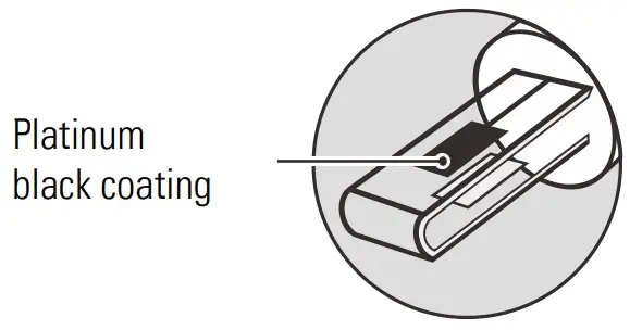
- Remove the conductivity electrode from service and rinse the platinum sensor on the bottom of the electrode.
- Do not touch the platinum black coating on the sensor surface and always keep it clean.
- If there is a build-up of solids inside the sensor, remove carefully,then recalibrate the electrode.
- If you do not use the electrode for long periods, wipe clean with a lint-free tissue and store the electrode in a dry and cool area.
- If your electrode is model IE-50HT, store the electrode with tap water. This sensor needs to be kept wet always.
 Appendix
 Appendix
Troubleshooting
| Fault | Cause and Corrective Action |
|
—–
| Electrode dried out. Soak the conductivity electrode in tap water for about 10 minutes. |
| Measurement exceeded the maximum range. Check the electrode and sample. | |
| Drifting erratic readings | Check whether electrode is contaminated, clogged or broken. |
|
| Setting value does not match calibration solution. Reset the calibration value or check the calibration solution. |
| Electrode is broken. Replace the conductivity electrode. |
Preparation of Conductivity Standard Solutions
- Place the analytical grade potassium chloride (KCl) in a beaker and dry in an oven for about 3 hours at 105° C (221° F), then cool to room temperature.
- Add the reagent to a 1 liter volumetric flask according to the instructions in table below.
Conductivity Standard Reagent Weight 84 µS/cm KCl 42.35 mg 1413 µS/cm KCl 745.5 mg 12.88 mS/cm KCl 7.45 g 111.8 mS/cm KCl 74.5 g
3. Fill the distilled water to the mark, mix the solution until the reagent is completely dissolved.
Calculating the Temperature Coefficient
- Do not connect the temperature probe to the meter.
- Press and hold the °C key to enter the temperature setting.
- Press the ▲/ ▼key to set the temperature to 25° C and press the Enter key to confirm.
- Place the conductivity electrode into the sample solution, record the temperature value TA and conductivity value CTA.
- Condition the sample solution and electrode to a temperature TB that is about 5 to 10° C different from TA. Record the conductivity value CTB.
- Calculate the temperature coefficient using the formula below.
TC = [CTB – CTA ] / [CTA (TB – 25) – CTB (TA – 25)]
Where:
TC = Temperature coefficient
CTA = Conductivity at temperature A
CTB = Conductivity at temperature B
TA = Temperature A
TB = Temperature B
Calculating the TDS Conversion Factor
To determine the TDS factor of sample solution use the formula below.
Factor = Actual TDS / Actual Conductivity @25° C
Where:
Actual TDS = value from the high purity water and precisely weighed
NaCl or KCL reagent
Actual Conductivity = the meter measured conductivity valueFor example:
Dissolve 64 grams of the potassium chloride (KCl) reagent in 1 liter distilled water. If measured conductivity is 100 mS/cm, then TDS factor is 0.64.
Optional Accessories
| Order Code | Description |
| IE-50LT | For measuring the pure water |
| IE-50MT | For general purpose applications |
| IE-50HT | For measuring the high conductivity liquids |
| ECCS-84 | Conductivity standard solution 84 µS/cm, 480 ml |
| ECCS-1413 | Conductivity standard solution 1413 µS/cm, 480 ml |
| ECCS-1288 | Conductivity standard solution 12.88 mS/cm, 480 ml |
| ECCS-1118 | Conductivity standard solution 111.8 mS/cm, 480 ml |
Meter Specifications
| Model | BI-650 |
| Conductivity | |
| Range | 0.01 µS/cm to 200.0 mS/cm |
| Resolution | 0.001, 0.01, 0.1, 1 |
| Accuracy | ±1% F.S. |
| Calibration Points | 1 to 3 points |
| Calibration Solutions | 84 µS/cm, 1413 µS/cm, 12.88 mS/cm, 111.8 mS/cm |
| Temperature Compensation | 0 to 100°C (32 to 212°F), automatic |
| Temperature Coefficient | 0.0 to 10.0%/°C |
| Reference Temperature | 25°C |
| Cell Constant | K = 0.1, 1, 10 |
| TDS | |
| Range | 0.00 to 10.00 ppt (max. 200 ppt) |
| Resolution | 0.01, 0.1, 1 |
| Accuracy | ±1% F.S. |
| TDS Factor | 0.1 to 1.0 (default 0.5) |
| Temperature | |
| Range | 0 to 100°C (32 to 212°F) |
| Resolution | 0.1°C (0.1°F) |
| Accuracy | ±1°C (±1.8°F) |
| Calibration Point | 1 point |
| Communication | |
| Signal Output | 4 to 20 mA |
| Low or High Alarm | 0.02 µS/cm to 20.0 mS/cm |
| Load | 500 ohm |
| Communication Interface | RS485 |
| Other Specifications | |
| Operating Temperature | 5 to 50°C 41 to 122°F) |
| Storage Temperature | 0 to 60°C (32 to 140°F) |
| Relative Humidity | < 80% (non-condensing) |
| Display | LCD, 70 × 45 mm (2.9 × 1.7 in.) |
| Power Requirements | DC 24V |
| Dimensions | 96 (L) × 96 (W) × 75 (H) mm, (3.7 × 3.7 × 2.9 in.) |
| Weight | 350 g (12.3 oz.) |
Disposal
This product is required to comply with the European Union’s Waste Electrical and Electronic Equipment (WEEE) Directive 2002/96/EC and may not be disposed of in domestic waste. Please dispose of product in accordance with local regulations at the collecting point specified for electrical and electronic equipment.
Warranty
The warranty period for meter is one year from the date of shipment. Above warranty does not cover the electrode and standard solution. Out of warranty products will be repaired on a charged basis. The warranty on your meter shall not apply to defects resulting from:
- Improper or inadequate maintenance by customer
- Unauthorized modification or misuse
- Operation outside of the environment specifications of the products.
For more information, please contact the supplier.
![]() Office: 4715 Castlewood St., Sugar land, TX 77479, USA
Office: 4715 Castlewood St., Sugar land, TX 77479, USA
Tel: (+1) 346-762-7358
E-mail: [email protected]
Factory: A10, No.2066, Laifang Rd., Shanghai 201615, China
Tel: (+86) 21-6404-1598
E-mail: [email protected]![]() www.bante-china.com
www.bante-china.com
http://bante-china.com/enHome/
The information in this document is subject to change without notice.
Copyright © Bante Instruments Inc, 2022. All rights reserved.


