![]()
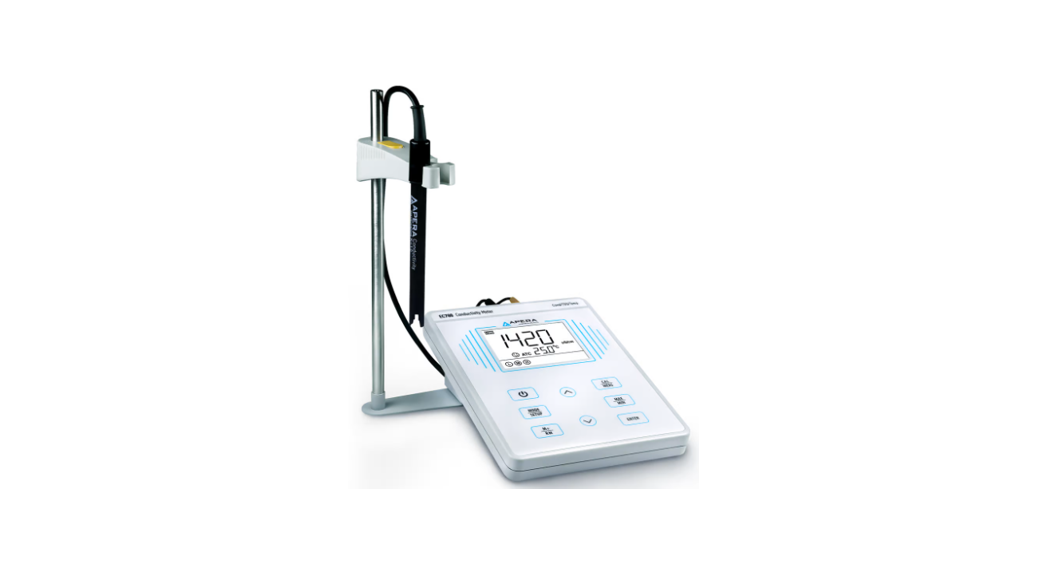
EC700 Benchtop Conductivity Meter
Instruction Manual
Brief Introduction
Thank you for purchasing Apera Instruments EC700 Benchtop Conductivity Meter.
This instrument is an outstanding combination of advanced electronics desin and sensor technology. It’s the most economical choice of a reliable lab benchtop conductivity meter.
Please read this maual carefully to properly use and maintain the meter. Apera Instruments reserves the right to update the contents of this manual without giving prior notices.
1.1 Main Features
- The meter has a built-in microprocessor chip, which enables intelligent functions such as automatic calibration, automatic temperature compensation, data storage, parameter setup, max/min reading display, etc.
- The advanced automatic calibration mode has calibration guide and self-diganosis functions, automatically recognizing standard calibration solutions.
- The advanced digital processing technology intelligently improves the meter’s response time and measuring accuracy with stable reading display mode available.
- The kit comes with a combination conductivity electrode with temperature sensor, measuring conductivity and temperature simultaneously, and allows for automatic temperature compensation.
- IP54 dustproof and spillproof. Connectors are protected by silicone seal caps, effectively ensuring the reliability and service life of the meter under harsh environment.
- Detachable electrode holder and 3 bottles of conductivity calibration solutions come with the kit for convenient use.
Technical Specifications
| Conductivity | Range | Conductivity: 0-200.0 mS/cm, divided into 4 ranges: (0-199.9) μS/cm, (200-1999) μS/cm, (2.00-19.99) mS/cm,(20.0-199.9) mS/cm TDS: (0-100) g/lL devided into 4 ranges: (0-99.9) mg/L, (100-999) mg/L, (1.00-9.99) g/L, (10.0-100.0) g/L |
| Resolution | Conductivity: 0.1/1 μS/cm; 0.01/0.1 mS/cm TDS: 0.1/1 mg/L, 0.01/0.1 g/L | |
| Accuracy | ±1.0% F.S ±1 digit | |
| Temperature Compensation | 0 to 50 ˚C (Auto or Manual) | |
| Electrode Constant | 0.1/1/10 cm-1 | |
| Reference Temperature | 25 ˚C | |
| Temperature Compensation Coefficient | 0.00-9.99%/ ˚C, default value: 2.00%/ ˚C | |
| Calibration | 1-4 point Auto Calibration |
| Temp. | Range | 0 to 100˚C; 32 to 212°F |
| Resolution | 0.1˚C; 0.1/1°F | |
| Accuracy | ±0.5˚C ±1 digit | |
| Others | Data Storage | 50 groups |
| Storage Content | Numberings, Measurement, Unit, Temperature, Temperature Compensation Status | |
| Power | DC9V/300mA | |
| IP Ratings | IP54 dustproof and spillproof | |
| Size and Dimension | (240*235*103) mm/1kg |
Instrument Description
3.1 LCD Display
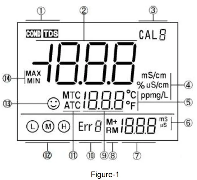
(1) — Measurement mode
(2) — Measurement value
(3) — Calibration icons and numberings
(4) — Measurement unit
(5) — Temperature unit
(6) — The unit displayed during calibration
(7) — The value displayed during calibration, numberings for storage and recall, and reminder icons
(8) — Icons for data storage and recall — M+: store measuring data; RM: Recall measuring data
(9) — Temperature and reminder icons
(10) — Self-Diagnosis icons and numberings
(11) — Temperature compensation mode icons — ATC: Auto Temperature Compensation; MTC: Manual Temperature Compensation
(12) — Completed calibration icons
(13) — Stable reading icon
(14) — Icons for maximum and minimum values
3.2 Keypad
3.2.1. Keypad operations
Short press —– <1.5 seconds;
Long press —– >1.5 seconds.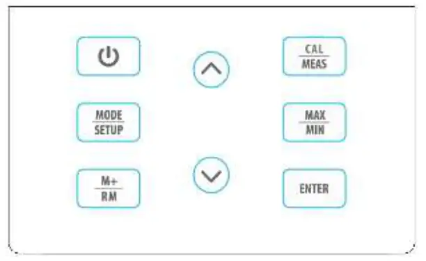
3.2.2 For keypad operation, please see Table-1.
Table – 1 Keypad operations and descriptions
| Keypad | Operation | Functions |
 | Short Press | • Power on/off |
| Short Press | • Select measuring mode: Cond→TDS. | |
| Long Press | • Enter parameter setting:P1→P2→…P6. | |
| Short Press | • Enter Calibration mode • Cancel any operation and go back to measurement mode | |
| Short Press | • In calibration mode, press to conduct calibration • In parameter setting, press to confirm selection | |
| Short Press | • Store measuring data | |
| Long Press | • Recall stored measuring data | |
 | Short Press or Long Press | 1. In manual temperature compensation mode, short press to change temperature, long press to change quickly 2. In parameter setting mode, short press to change parameter and settings. 3. In recall mode, short press to change numberings, long press to change quickly. |
 | Short Press | 4. Buttons for max/min values (refere to section 3.6) |
3.3 Connectors
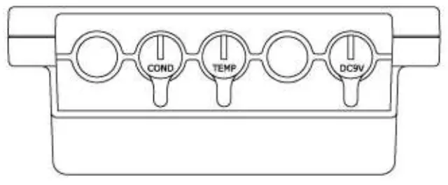 | ||
| Symbol | Connector Name | Connector Type |
| COND | Socket for conductivity electrode | BNC |
| TEMP | Socket for temperature sensor | RCA |
| DC9V | DC9V power socket | Φ2.5 direct type |
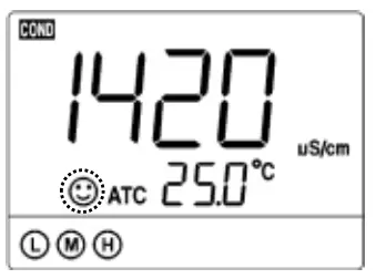
3.4 Stable reading display mode
When the measuring value is stable, smiley face icon![]() appears on LCD, see Figure-3. Please do not get the reading value or make calibration until the icon
appears on LCD, see Figure-3. Please do not get the reading value or make calibration until the icon![]() appears and stays.
appears and stays.
3.5 Data storage, recall, and deletion
3.5.1 Storage
When the measurement is stable, press![]() key, the meter displays M+ icon and storage numberings on LCD and stores the measuring data. In Figure-4, the meter stores the first group of the measuring data. Press
key, the meter displays M+ icon and storage numberings on LCD and stores the measuring data. In Figure-4, the meter stores the first group of the measuring data. Press![]() again to keep storing.
again to keep storing. 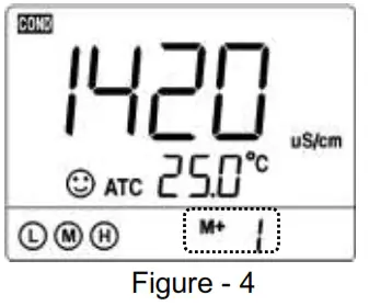
3.5.2 Recall stored data
In the measurement mode, long press![]() key to recall the last stored Measuring data. The meter displays RM icon and storage numberings. In Figure-5, the meter is recalling the 28th stored measuring data. Keep pressing
key to recall the last stored Measuring data. The meter displays RM icon and storage numberings. In Figure-5, the meter is recalling the 28th stored measuring data. Keep pressing ![]() to recall successively the stored measuring data. Press and hold
to recall successively the stored measuring data. Press and hold ![]() to quickly recall the stored measuring data. Short press
to quickly recall the stored measuring data. Short press ![]() to go back to measurement mode.
to go back to measurement mode. 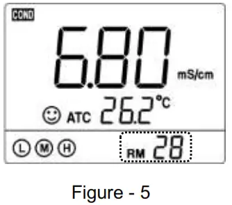
3.5.3 Clear stored data
The meter can store 50 groups of data. Once the storage is full, if user presses ![]() again, the FUL icon will be displayed on LCD (see Figure-6).
again, the FUL icon will be displayed on LCD (see Figure-6).
The storage needs to be cleared in parameter setting P4 so as to keep storing data. The numberings in M+ indicates the total number of stored data; The numberings in RM indicates the number of stored data in current mode (cond/TDS). 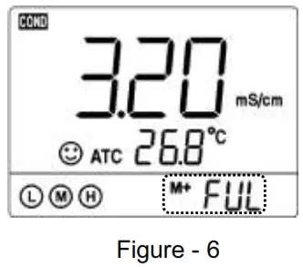
For example, if 20 groups of data is stored in conductivity mode, and 10 groups in TDS mode, then the numberings for M+ will be “M+30” in both conductivity and TDS mode; the numberings for RM in conductivity mode would be “RM20”, in TDS mode “RM10”.
3.6 Max/Min Function
Use this function to display the maximum or minimum records out of groups of measuring data. In measurement mode, press![]() , LCD will display flashing icons of “MAX/MIN”, indicating the meter has entered the mode of recording maximum and minimum data. After testing, press
, LCD will display flashing icons of “MAX/MIN”, indicating the meter has entered the mode of recording maximum and minimum data. After testing, press![]() again, LCD will alternately display the maximum and minimum value in the past measurements. Press
again, LCD will alternately display the maximum and minimum value in the past measurements. Press![]() to go back to regular measurement mode.
to go back to regular measurement mode.
Conductivity Measurement
4.1 Preparation
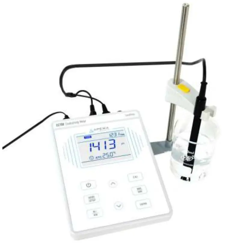
4.1.1 Install the electrode holder
The electrode holder is comosed of a metal stand base, a supporting pole, and a electrode clip. First, install the metal stand base to the meter (screw it on). Please note that the metal base can be installed on either side of the meter. Then install the supporting pole on the metal stand base, and then install the electrode clip on the supporting pole.
4.1.2 Connect the power adapter
Plug the power adapter tightly into the DC9V socket. The power’s voltage should meet the requirements listed on the power adapter.
4.2 Conductivity Electrode Information
4.2.1 Conductivity Electrode
The meter comes with the 2301T-F combination conductivity electrode (K=1.0) with built-in temperature sensor, which enables the automatic temperature compensation. The electrode’s housing adopts polycarbonate materials, which is resistant to shocks and corrosion.
4.2.2 Electrode Connectors
The conductivity electrode has two connectors: the BNC connector connects the conductivity sensor, the RCA connector connects the temperature sensor. Plug these two connectors into ‘COND” and “TEMP” sockets. Please note do not pull the cables in case of poor contact. Please keep the connectors clean and dry. Refer to section 4.8 regarding how to properly maintain the Conductivity electrode.
4.2.3 Use the Electrode
Stir the electrode for a few seconds after it’s dipped into the solution and then let it stand still such that the bubbles inside the probe can be removed and a stable measurement can be quickly obtained.
4.3 Information regarding Calibration
4.3.1 Conductivity standard solutions
The meter automatically recognizes calibration solutions. 1 point or multi-points calibration (up to 4 points) can be adopted. The calibration icons stand for 4 different calibration points ( ![]() stands for two standard solutions), see Table-2:
stands for two standard solutions), see Table-2:
Table-2
| Calibration icon | pH standard buffer series | |
| 4-Point calibration | 84 μS/cm | |
| 1413 μS/cm | ||
| 12.88 mS/cm | ||
| 111.8 mS/cm | ||
4.3.2 How often to calibrate
- We recommend to calibrate the conductivity meter once per month under normal conditions.
- If the requirement for accuracy is high or the temperature of the test sample has a big difference to the reference temperature (25 ˚C), we recommend to do the calibration once a week.
- Users can tell if the meter needs a calibration by testing the standard calibration solutions. If the measurements you get have a big difference to the standard value of the calibration solutions, then a calibration is necessary.
- For new electrodes or the meter that has been restored to factory default setting, we recommend to conduct 3-4 points calibration. For general uses, users can choose the calibration solutions that are close to the test samples to conduct 1 or 2 points calibration.
4.4 Conductivity Calibration (take 1413 μS as an example)
4.4.1. Rinse the electrode in distilled or pure water, allow it to dry, wash with a little of standard solution and submerge it in standard solution. Stir the solution briefly and allow it to stay in the solution until a stable reading is reached.
4.4.2. Press![]() key to enter the calibration mode. The “CAL” icon will flash at the top right, and the scanning and locking process of calibration solution will appear at the bottom right.
key to enter the calibration mode. The “CAL” icon will flash at the top right, and the scanning and locking process of calibration solution will appear at the bottom right.
4.4.3. When the meter locks 1413 μS, stable icon![]() will display on LCD. Press
will display on LCD. Press![]() key to complete calibration. “End” icon will show up and the meter will return to measuring mode and
key to complete calibration. “End” icon will show up and the meter will return to measuring mode and![]() will show up on the bottom left (see Figure-7).
will show up on the bottom left (see Figure-7).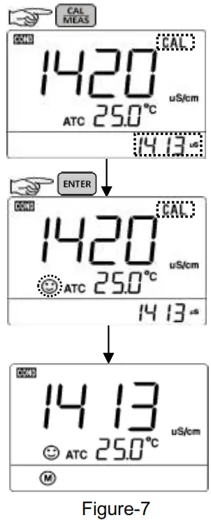
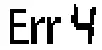
Note: pressing![]() before the reading being stable (
before the reading being stable (![]() shows up and stays), the Err4 self-diagnosis icon will appear (see section 6.5.2).
shows up and stays), the Err4 self-diagnosis icon will appear (see section 6.5.2).
4.4.4. For multi-point calibration, please repeat clause 4.3.1-4.3.2 until all the calibration is done. The meter can repeat calibration in the same calibration solution until the stable value is reached.
4.5 TDS and Conductivity
4.5.1. TDS and conductivity is linear related. The conversion factor is 0.40-1.00. Adjust the factor from parameter P2.6. The factory default setting is 0.71 and please refer to Section 7.4. The meter only needs to be calibrated in Conductivity mode, then after calibration of conductivity, the meter can switch from conductivity to TDS.
4.5.2. Adjust TDS conversion factor in parameter setting P4 according to the data collected during testing and experience. Table – 10 lists some commonly used Conductivity and TDS conversion factors. This is for your reference only.
Table – 10 Conductivity and TDS conversion factors
| Conductivity of solution | TDS conversion factor |
| 0-100 μS/cm | 0.60 |
| 100-1,000 μS/cm | 0.71 |
| 1-10 mS/cm | 0.81 |
| 10-100 mS/cm | 0.94 |
4.6 Sample Test
4.6.1. Rinse conductivity electrode in distilled or pure water, dry it, and submerge it in the sample solution. Stir the solution briefly and allow it to stay in the sample solution until a stable reading is reached and icon![]() appears on LCD, then get the reading value, which is the conductivity value of the solution.
appears on LCD, then get the reading value, which is the conductivity value of the solution.
4.6.2. During the process of calibration and measurement, the meter has self-diagnosis functions, indicating the relative information as below: Table – 8.
Table – 8 Self-diagnosis information of conductivity measurement mode
| Display Icons | Contents | Checking |
| Wrong conductivity calibration solution or the meter recognition of calibration solution is out of range. | 1. Check whether conductivity calibration solution is correct. 2. Check whether the meter connects the electrode well. 3. Check whether the electrode is damaged. | |
 | Press | Press |
 | During calibration, the measuring value being unstable for over 3 minutes. | 1. Shake the electrode to eliminate bubbles in electrode head. 2. Replace with new conductivity electrode. |
4.6.3. Factory default setting
For factory default setting, please refer to parameter setting P7 (Section 4.7.2). With this function, all calibration data is deleted and the meter restores to the theory value. Some functions restore to the original value. When calibration or measurement fails, please restore the meter to factory default setting and then perform recalibration or measurement. Please note once set the factory default, all the data deleted will be irretrievable.
4.7 Parameter Setting
Table-9
| Symbol | Parameter setting content | Parameter | Factory default setting |
| P1 | Select electrode constant | 0.1, 1.0, 10 | 1.0 |
| P2 | Select reference temperature | 15 – 30 ℃ | 25℃ |
| P3 | Adjust temperature compensation coefficient | 0.00 – 9.99% | 2.00% |
| P4 | Adjust TDS Factor | 0.40 – 1.00 | 0.71 |
| P5 | Select temperature unit | ℃ – ℉ | ℃ |
| P6 | Clear stored data | No – Yes | No |
| P7 | Restore to factory default | No – Yes | No |
4.7.1 How to do the parameter setting:
In measurement mode, long press![]() to enter parameter setting P1. Then press
to enter parameter setting P1. Then press ![]() or
or![]() to change menu from P1 to P2…P7. For details, please see Table-10.
to change menu from P1 to P2…P7. For details, please see Table-10.
Table-10 Parameter Setting
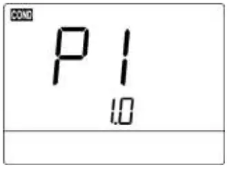 | P1 — Select electrode’s constant(1.0—10.0—0.1) 1. Long press 2. Press 3. Press |
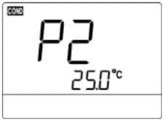 | P2—Select reference temperature (25.0℃—18.0℃—20.0℃) 1. Press 2. Press |
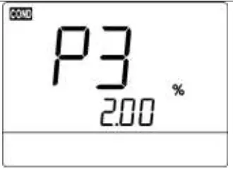 | P3—Adjust temp. compensation coefficient (0.00-9.99%) 1. Press 2. Press |
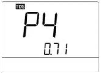 | P4—Adjust TDS Factor (0.40-1.00) 1. Press 2. Press |
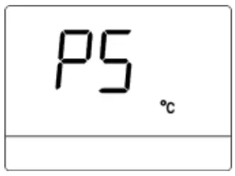 | P5 —(°C—°F) 1. Press 2. Press |
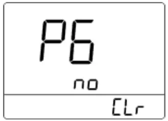 | P6 — Clear storage (No—Yes) 1. Press No— not to clear data storage; Yes—clear all data storage 2. Press |
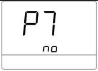 | P7 — Return to factory default mode (No—Yes) Press No— not return to factory default mode; Yes—return to factory default mode |
4.8 Conductivity Electrode’s Maintenance
4.8.1. Always keep the conductivity electrode clean. Before taking a measurement, rinse the electrode in pure water. It is recommended to rinse it again in the sample solution. When submerge the electrode in solution, stir the solution briefly to eliminate air bubbles and allow it to stay until a stable reading is reached. Conductivity electrodes are usually stored dry. For conductivity electrodes that haven’t been used for a long time, users should soak the electrode in 12.88 mS calibration solution for 5-10 minutes, or to soak it in tap water for 1 to 2 hours. Rinse the electrode in pure water after measurement.
4.8.2. The sensing rod of Model 2301T-F conductivity electrode is coated with platinum black to minimize electrode polarization and expand measuring range. The platinum black coating adopted our special processing technology, which improves the electrode performance and the firmness of the coating. If the platinum black electrode is stained, gently clean the electrode with soft brush in warm water containing detergent or alcohol.
Complete Kit
| Content | Quantity | |
| 5.1 | EC700 Benchtop Conductivity Meter | 1 |
| 5.2 | 2301T-F Plastic Combination Conductivity Electrode | 1 |
| 5.3 | Conductivity standard calibration solutions: (84μS/1413μS /12.88mS, 50ml for each) | 1 for each |
| 5.4 | 9V Power Adapter | 1 |
| 5.5 | Electrode Holder | 1 set |
| 5.6 | Instruction Manual | 1 |
Warranty
We warrant this instrument to be free from defects in material and workmanship and agree to repair or replace free of charge, at option of APERA INSTRUMENTS (Europe) GmbH, any malfunctioned or damaged product attributable to responsibility of APERA INSTRUMENTS (Europe) GmbH for a period of TWO YEARS (SIX MONTHS for the probe) from the delivery.
This limited warranty does not cover any damages due to:
Transportation, storage, improper use, failure to follow the product instructions or to perform any preventive maintenance, modifications, combination or use with any products, materials, processes, systems or other matter not provided or authorized in writing by us, unauthorized repair, normal wear and tear, or external causes such as accidents, abuse, or other actions or events beyond our reasonable control.
APERA INSTRUMENTS (Europe) GmbH
Wilhelm-Muthmann-Straße 18, 42329 Wuppertal Germany
Email: [email protected] | ww.aperainst.de | Tel. +49 202 51988998 ![]()


