![]()
Mircom BEAM200 Intelligent Beam Smoke Detectors
Description
The BEAM200 and BEAM200S single-ended reflected beam smoke detectors are uniquely suited for protecting open areas with high ceilings where other methods of smoke detection are difficult to install and maintain.
The BEAM200 and BEAM200S intelligent reflected beam smoke detectors are designed to be used with UL Listed compatible control panels only. Since all of the wiring is connected to one side, the installation of the single-ended reflective design is much easier than dual-ended projected beam detectors. Alignment is accomplished quickly via an optical sight and a 2 digit signal strength meter incorporated into the product. Listed for operation from –22°F to 131°F, the BEAM200 detector can be used in open area applications to provide early warning in environments where temperature extremes exceed the capability of other types of smoke detection.
The BEAM200 smoke detector includes one wired transmitter/receiver unit and one reflector. When smoke enters the area between the unit and the reflector it causes a reduction in the signal. The alarm is activated when the smoke level reaches the predetermined threshold.
Features
- 16 to 328 foot protection range
- Single-ended, reflective design
- Easiest alignment in the industry with digital display
- 6 field selectable sensitivity levels
- Optional integral NFPA 72 sensitivity test feature
- Removable plug-in terminal blocks
- Built-in automatic gain control compensates for signal deterioration from dust build-up
- Remote test station available
- Paintable cover
- Optional heater kits available
The BEAM200 device has four standard sensitivity selections along with two Acclimate™ settings. When either of the two Acclimate settings are selected, the detector automatically adjusts its sensitivity using advanced software algorithms to select the optimum sensitivity for the specific environment.
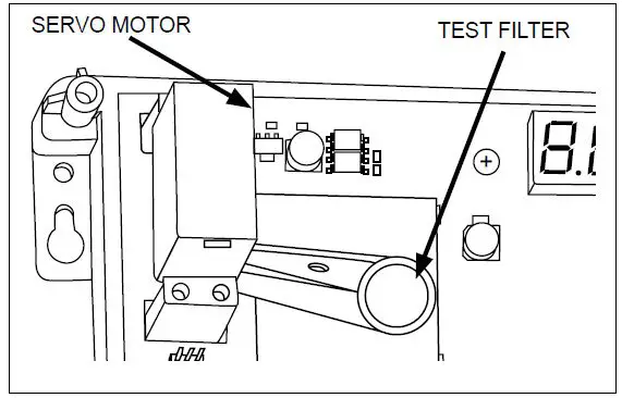
The BEAM200S model is equipped with an added feature, an integral sensitivity test feature that uses a test filter attached to a Servo motor inside the detector optics. Using the remote test station RTS151, the motor is activated and moves the filter in the pathway of the light beam, thereby testing detector sensitivity. This integral sensitivity test feature allows the user to quickly and easily meet the annual maintenance and test requirements of NFPA 72.
BEAM200 and BEAM200S Specifications
| Operational Specifications | |
| Protection Range | 16 ft to 328 ft (5 m to 100 m) |
| Adjustment Angle | ±10 Degrees horizontal & vertical (The optics move independent of the unit) |
|
Sensitivity Levels | Level 1 – 25% Level 2 – 30% Level 3 – 40% Level 4 – 50% Acclimate™ Level 1 – 30 to 50% Acclimate Level 2 – 40 to 50% |
| Fault Condition (Trouble) | 96% or more obscuration blockage In alignment mode Improper initial alignment Self-compensation limit reached |
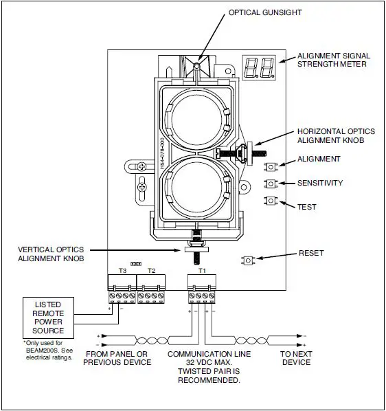
| Alignment Aid | Optical gunsight Integral signal strength indication 2 digit display |
| Alarm Indicator | Local red LED and remote alarm |
| Trouble Indicator | Local yellow LED and remote trouble |
| Normal Indicator | Local flashing green LED |
| Test/Reset Features | Integral Sensitivity Test Filter (BEAM200S only, requires additional external power supply) Sensitivity filter (Incremental scale on reflector) Local test switch Local reset switch Remote test and reset switch (Compatible with RTS151 and RTS151KEY test station) |
| Smoke Detector Spacing | On smooth ceilings, 30 to 60 feet between projected beams and not more than one-half that spacing between a projected beam and a sidewall. Other spacing may be used depending on ceiling height, airflow characteristics, and response requirements. See NFPA 72 and CAN/ULC S524. |
| Environmental Specifications | |
| Temperature | –22°F to 131°F (–30°C to 55°C) |
| Humidity | 10 to 93% RH Noncondensing |
| Electrical Specifications | |
| Voltage | 15 to 32 VDC |
| Avg. Standby Current (24VDC) | 2 mA Max |
| Avg. Current During Testing | 500 mA Max |
| Alarm Current (24VDC) | 8.5 mA Max |
| Fault Current (24VDC) | 4.5 mA Max |
| Alignment Mode Current (24VDC) | 20 mA Max |
| Mechanical Specifications | |
| Detector Dimensions | 10 in H × 7.5 in W × 3.3 in D (254 mm H × 191 mm W × 84 mm D) |
| Reflector Dimensions (16′ to 230′) | 7.9 in × 9.1 in (200 mm × 230 mm) |
| Reflector Dimensions (beyond 230′) | 15.7 in × 18.1 in (400 mm × 460 mm) |
| Electrical Specifications (BEAMHK) | |
| Voltage | 15 to 32 V |
| Current | 92 mA at 32 V |
| Power Consumption | 1.6 W at 24 V; 3 W at 32 V |
| Electrical Specifications (BEAMHKR) | |
| Voltage | 15 to 32 V |
| Current | 450 mA Max at 32 V (per reflector) |
| Power Consumption | 7.7 W at 24 V; 15 W at 32 V (per reflector) |
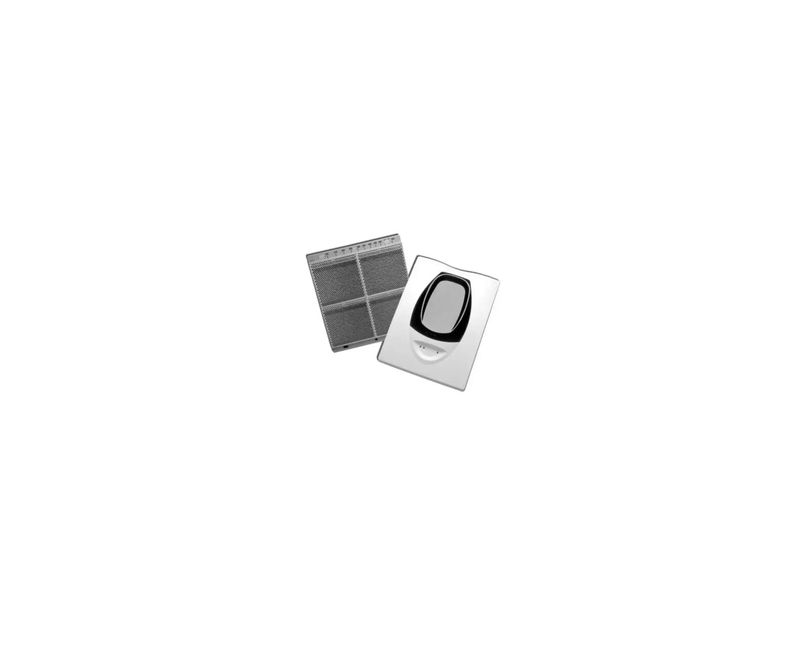
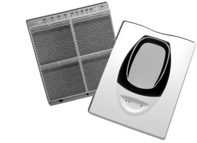
BEAM200(S) Parts
Advanced Test Feature (BEAM200S only)
Ordering Information
| Model Description | |
| BEAM200* | Intelligent beam smoke detector with 8˝ reflector |
| BEAM200S* | Intelligent beam smoke detector with 8˝ reflector and integral sensitivity test |
| Accessories | |
| BEAMLRK | Long range accessory kit. Includes 3 additional reflectors. (Required for applications in excess of 230 ft. [70m]) |
| BEAMMMK | Multi-mount kit. (Provides ceiling or wall mount capability with increased angular adjustment for either the beam or the reflector. When installed with the transmitter/receiver unit, BEAMSMK must be used as well) |
| BEAMSMK | Surface mount kit for use with BEAMMMK |
| 6500-MMK | Heavy duty multi-mount kit (for installations prone to vibration or where there is difficulty in maintaining the set angle. When installed with the transmitter/receiver unit, 6500-SMK must be used as well) |
| 6500-SMK | Surface mount kit for use with the 6500-MMK |
| BEAMHK | Heater kit for transmitter/receiver unit (See electrical requirements above) |
| BEAMHKR | Heater kit for reflector (See electrical requirements above) |
| RTS151 | Remote test station used to initiate the NFPA sensitivity test function |
| RTS151KEY* | Remote test station with key lock |
Add suffix “A” for ULC model.
THIS INFORMATION IS FOR MARKETING PURPOSES ONLY AND NOT INTENDED TO DESCRIBE THE PRODUCTS TECHNICALLY.
For complete and accurate technical information relating to performance, installation, testing and certification, refer to technical literature. This document contains intellectual property of Mircom. The information is subject to change by Mircom without notice. Mircom does not represent or warrant correctness or completeness.
Canada
25 Interchange Way Vaughan, Ontario L4K 5W3 Telephone: (905) 660-4655 Fax: (905) 660-4113
www.mircom.com
U.S.A.
4575 Witmer Industrial Estates Niagara Falls, NY 14305
Toll Free: (888) 660-4655 Fax Toll Free: (888) 660-4113


 Conventional Beam Smoke Detectors Owner's Manual")

 And Beam1224s(a) Conventional Beam Smoke Detectors Instructions")


